

Warn Industries PullzAll 885002, PullzAll 885004, PullzAll 885003 Service Manual
987605A1 Page 1 of 49
SERVICE GUIDE
For
WARN PULLZALL 230v AC
P/N 885002, 885003 & 885004
REPAIR / REPLACEMENT INSTRUCTIONS
TROUBLE SHOOTING GUIDE
987605A1 Page 2 of 49
WARNING
This guide identifies potential hazards and has important safety messages that help you and
others avoid personal injury or death. WARNING and CAUTION are signal words that
identify the level of hazard. These signal words mean:
WARNING signals a hazard that may cause serious injury or death, if you do not follow
recommendations. CAUTION signals a hazard that may cause minor to moderate injury,
if you do not follow recommendations.
This guide uses NOTICE to call attention to important mechanical information, and
Note: to emphasize general information worthy of special attention.
Notice
This guide has been provided for use by WARN Authorized Service Centers. Any
other use is prohibited.
Caution
Moving parts entanglement hazard
Failure to observe these instructions could lead to minor or moderate injury
Always take time to fully read and understand the Instructions.
Never operate this product if you are under 16 years of age.
Never operate this product when under the influence of drugs, alcohol or medications.
Read instructions thoroughly
Notice
Equipment damage
Always refer to the Wiring Diagram for all wiring schematics and specific details on how
to wire this WARN product
.
Read instructions thoroughly.
987605A1 Page 3 of 49
CONTENTS
1. GENERAL DESCRIPTION 04
2. DISASSEMBLY AND ASSEMBLY 06
2.1. Suggested Tools 06
2.2. Housing 07
2.3. Gear Train Assembly 11
2.4. Motor 17
2.5. Wire Rope Assembly 22
2.6. Safety Hook 28
2.7. Tail Hook 31
2.8. Drum Assembly 36
2.9. Wiring Diagrams 37
2.10. Filter Assembly 45
2.11. Torque Specifications 47
3. PULLZALL TROUBLE SHOOTING 48
4. SERVICE PACK LIST 50
987605A1 Page 4 of 49
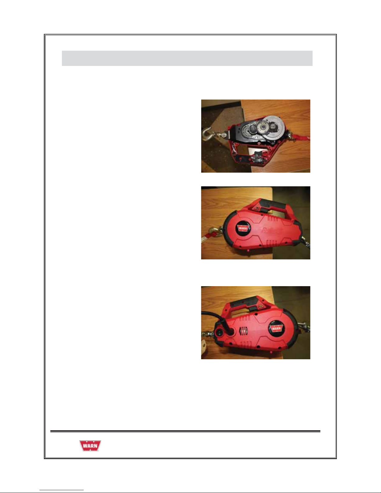
1. GENERAL DESCRIPTION
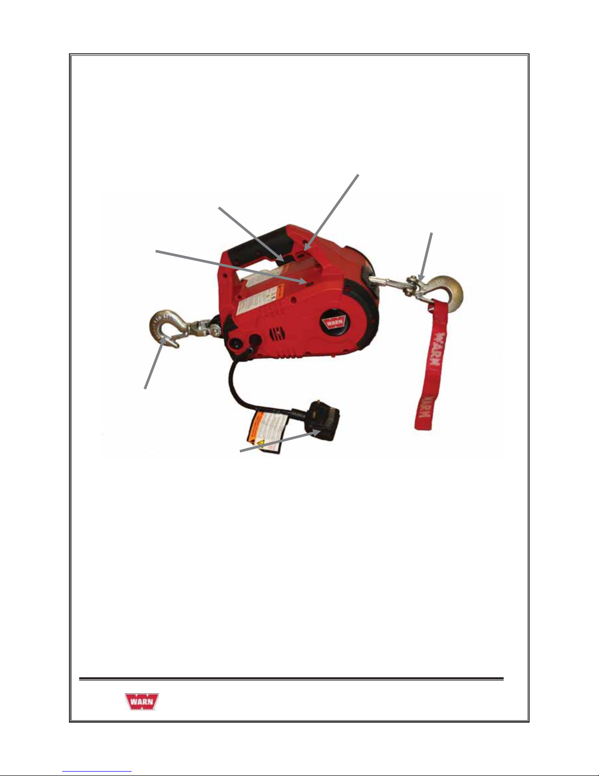
The PullzAll is a powerful, lightweight, easy-to-use handheld electric tool with the ability to lift or
pull up to 1,000 lbs / 454 kg. A strong Motor and Variable Speed Trigger Switch for power in and
power out operation, Wire Rope and Clasp Hook will allow you to move heavy items into place
smoothly and precisely. These features equate to saving both time and money.
The PullzAll will help get the job done easier, faster, and with less manual labor than a come-a-
long or chain fall, making you more productive. The PullzAll is for the tradesperson, farmer /
rancher, or anyone that needs to lift or pull up to 1,000 lbs / 454 kg. This makes PullzAll ideal for
construction, pipe fitting, iron work, equipment and plant maintenance, farm and ranch use, auto
shops, garages, machine shops, home improvement, hunting, camping, and more.
PullzAll 230v AC Specifications:
1. Part number 885002 (UK), 885003 (EU) & 885004 (AUS).
2. Light weight and portable.
3. Powerful 230 Volt AC Motor.
4. 1,000 lbs (454 kg) lifting / pulling capacity.
5. 15'(4.6m) of 7/32"(0.56cm) diameter Wire Rope.
6. Variable Speed Control for precision load placement.
7. Convenient forward/reverse Switch.
8. Electronic Load Limiter with LED indicator for operator feedback.
987605A1 Page 5 of 49
Runs on 230v
AC Power
15’ of 7/32” Wire
Rope with Industrial
Grade Hoo
k
Versatile Swivel
Anchor Hook
Electronic Load
Limiter with LED
Indicator for Operator
Feedback
Handle with Trigger
for Variable Speed
Control
Convenient
Forward/Reverse
1000 lbs/454 Kg
Lifting/Pulling
Ca
p
acity
987605A1 Page 6 of 49
2. DISASSEMBLY AND ASSEMBLY
2.1 SUGGESTED TOOLS
1. Hammer
2. Snap ring plier
3. Allen key set
4. Screw driver
5. Cutting plier
6. Pin remover (Punch)
7. Insulation tape
8. Gloves
987605A1 Page 7 of 49
2.2 HOUSING
Before opening the Housing follow the below instructions:
Power Cord
Always unplug the product while rigging, when not in use or during maintenance and cleaning.
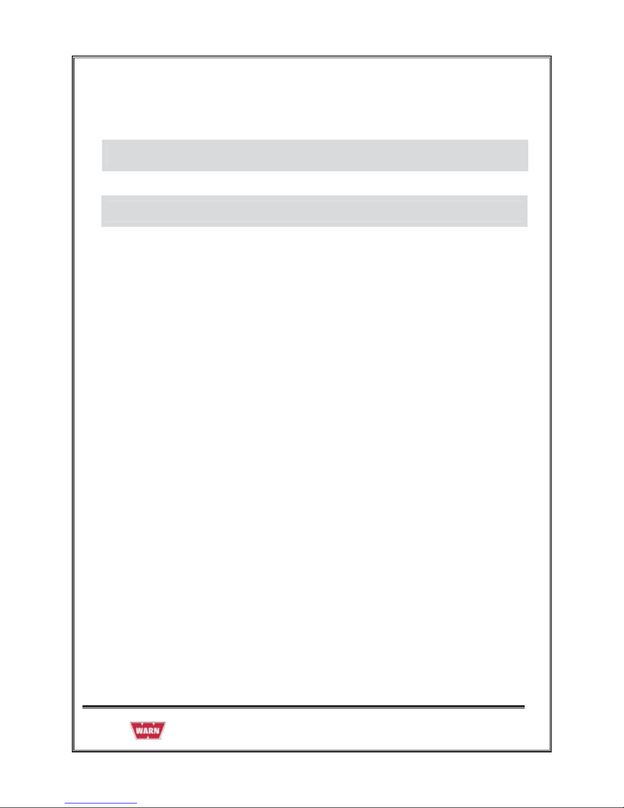
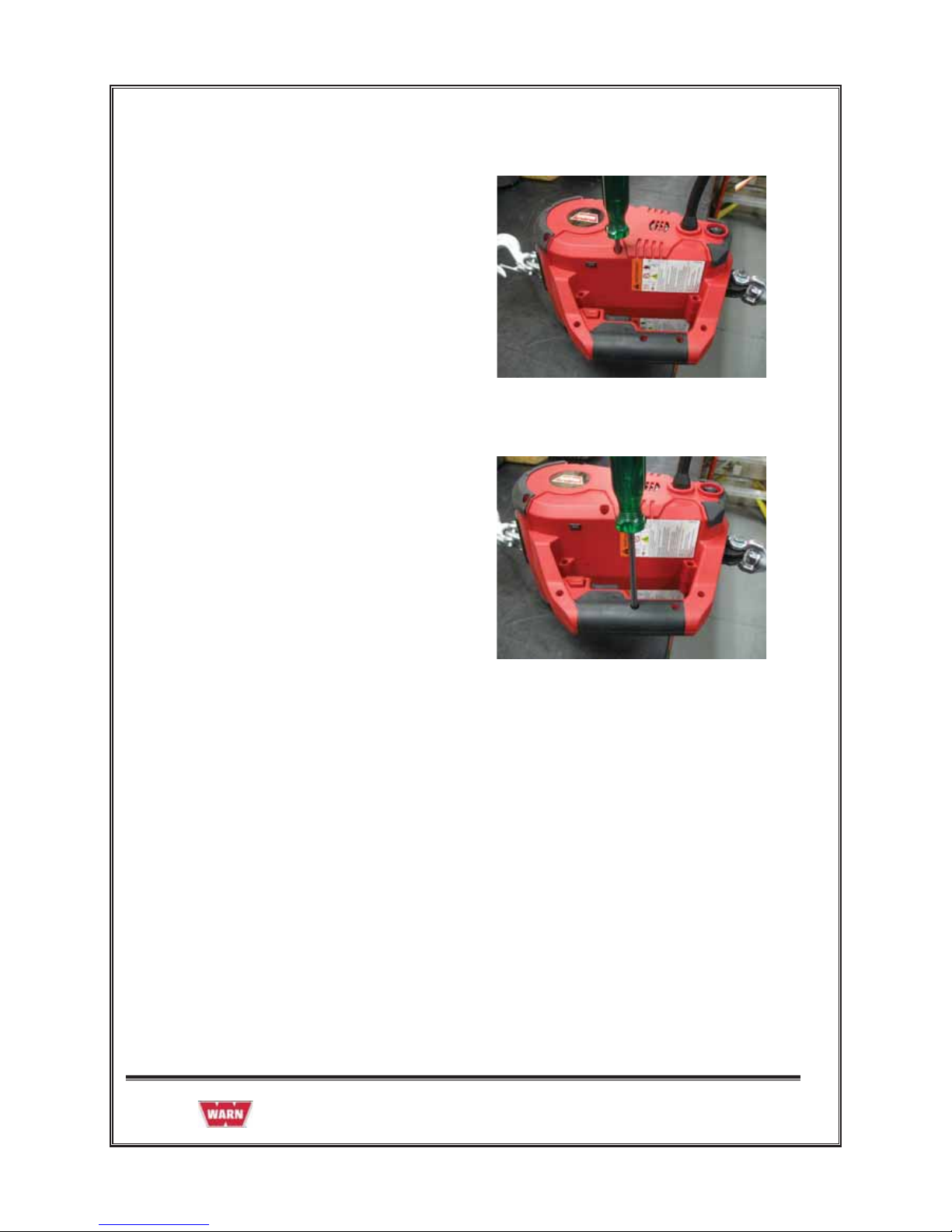
2.2.1 REMOVAL OF HOUSING
1. Remove the screws (#6 x .75), Qty 7
from Handle.
2. Remove the screws (#8 X 1.25), Qty 6
from the main body of the Housing
987605A1 Page 8 of 49
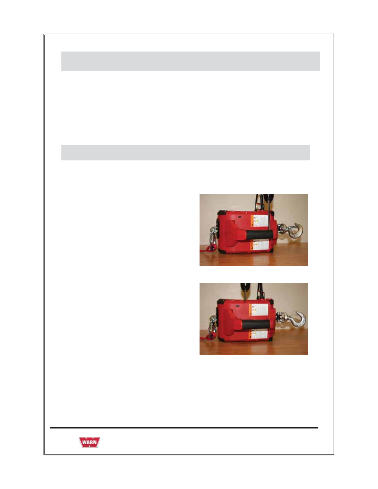
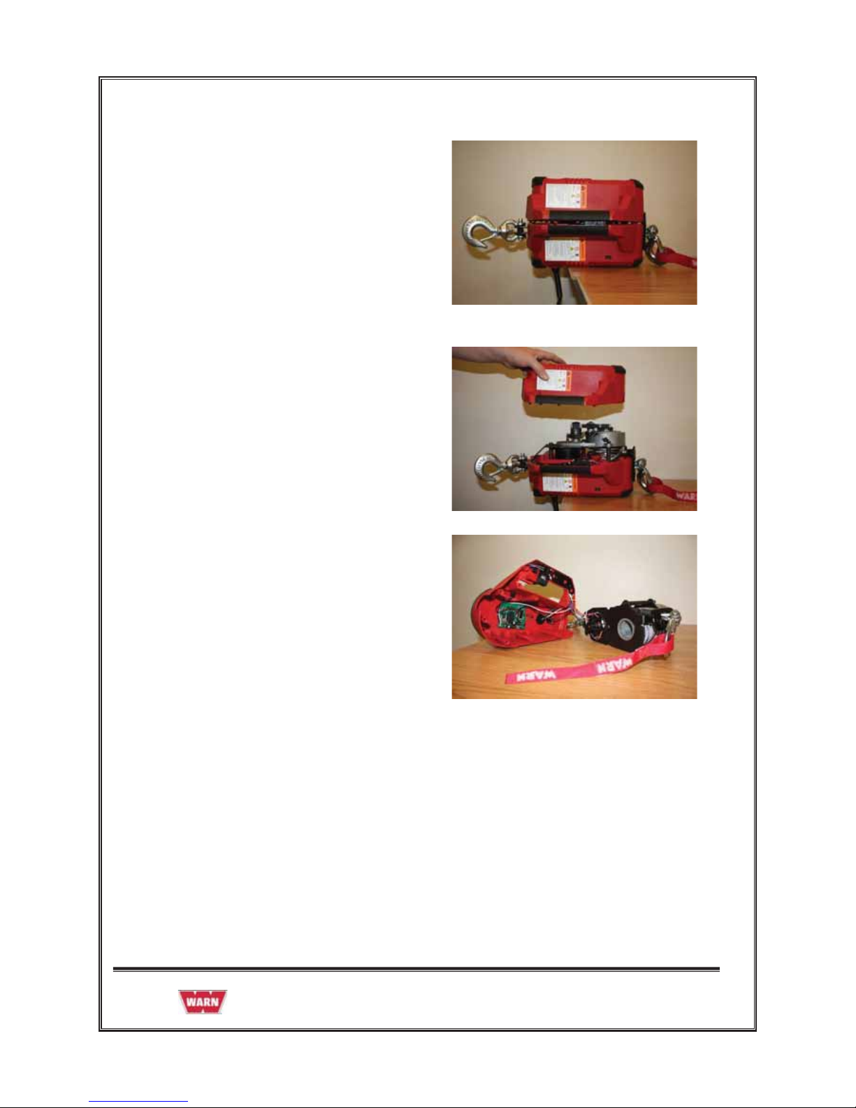
3. Keep the assembly on the work bench
facing the cover in the direction as shown
in the figure.
4. Remove the Plastic Housing -left hand
from the assembly as shown in the
figure.
5. Remove the Main Chassis from the
Plastic Housing - right hand and place it
on the work bench.
987605A1 Page 9 of 49
2.2.2 ASSEMBLY OF HOUSING
1. Install the Main Chassis in the Plastic
Housing - right hand as shown in the
figure.
2. Install the Plastic Housing -left hand on
the assembly as shown in the figure.
3. Flip the assembly as show in the figure.
987605A1 Page 10 of 49
4. Install the screws (#8 X 1.25), Qty 6
from the main body of the Housing
5. Install the screws (#6 x .75), Qty 7
near Handle
Note: When replacing the Housings with a Housing Service kit, be sure to affix all appropriate
labels from the service kit onto the new housings, using the housings being replaced as a guide
for placement of your new labels. Your service kit will include extra labels for other languages
and markets that can be discarded after you select the ones needed for your product.
987605A1 Page 11 of 49
2.3 GEAR TRAIN ASSEMBLY
• If the gear sets are worn or damaged, the entire PullzAll must be replaced, no replacement
parts are available.
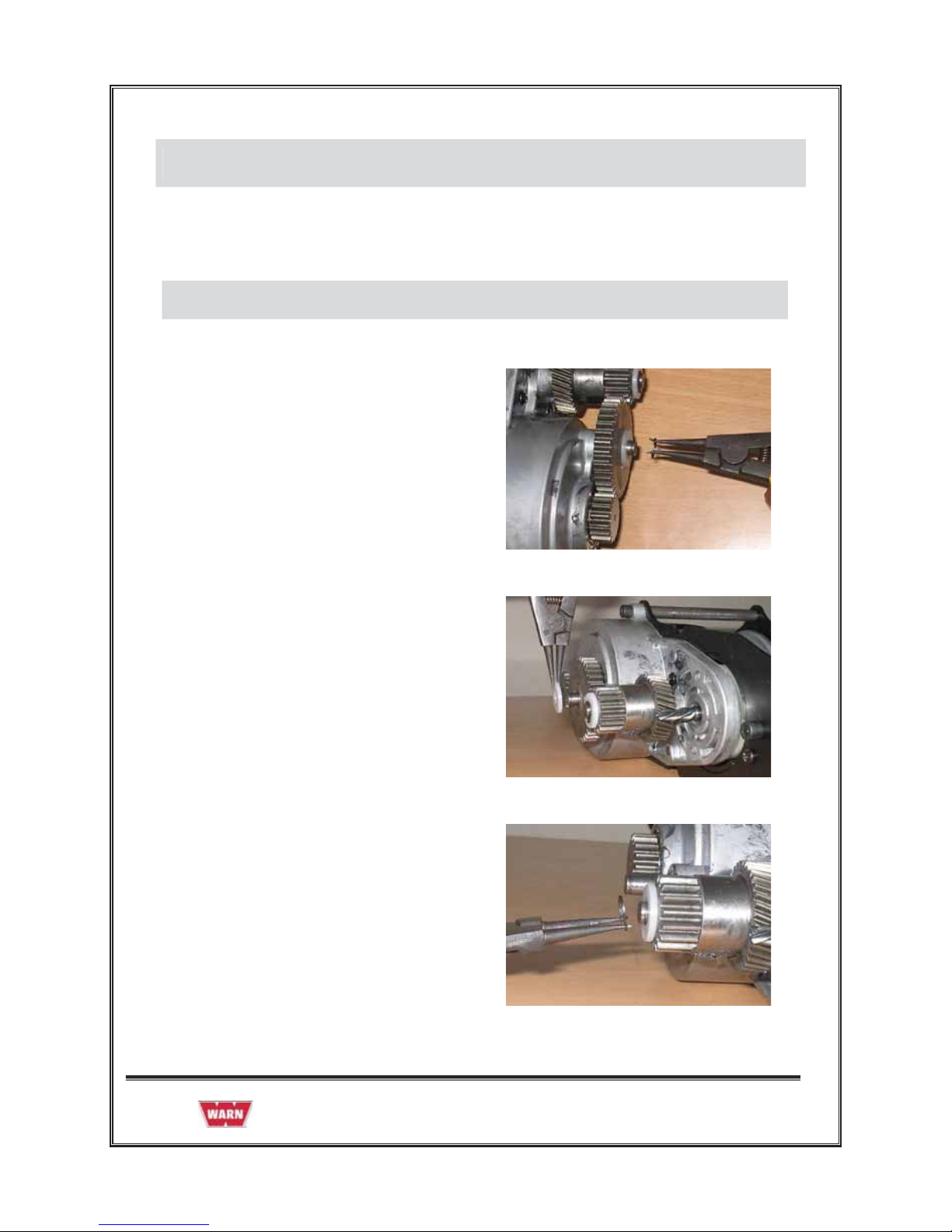
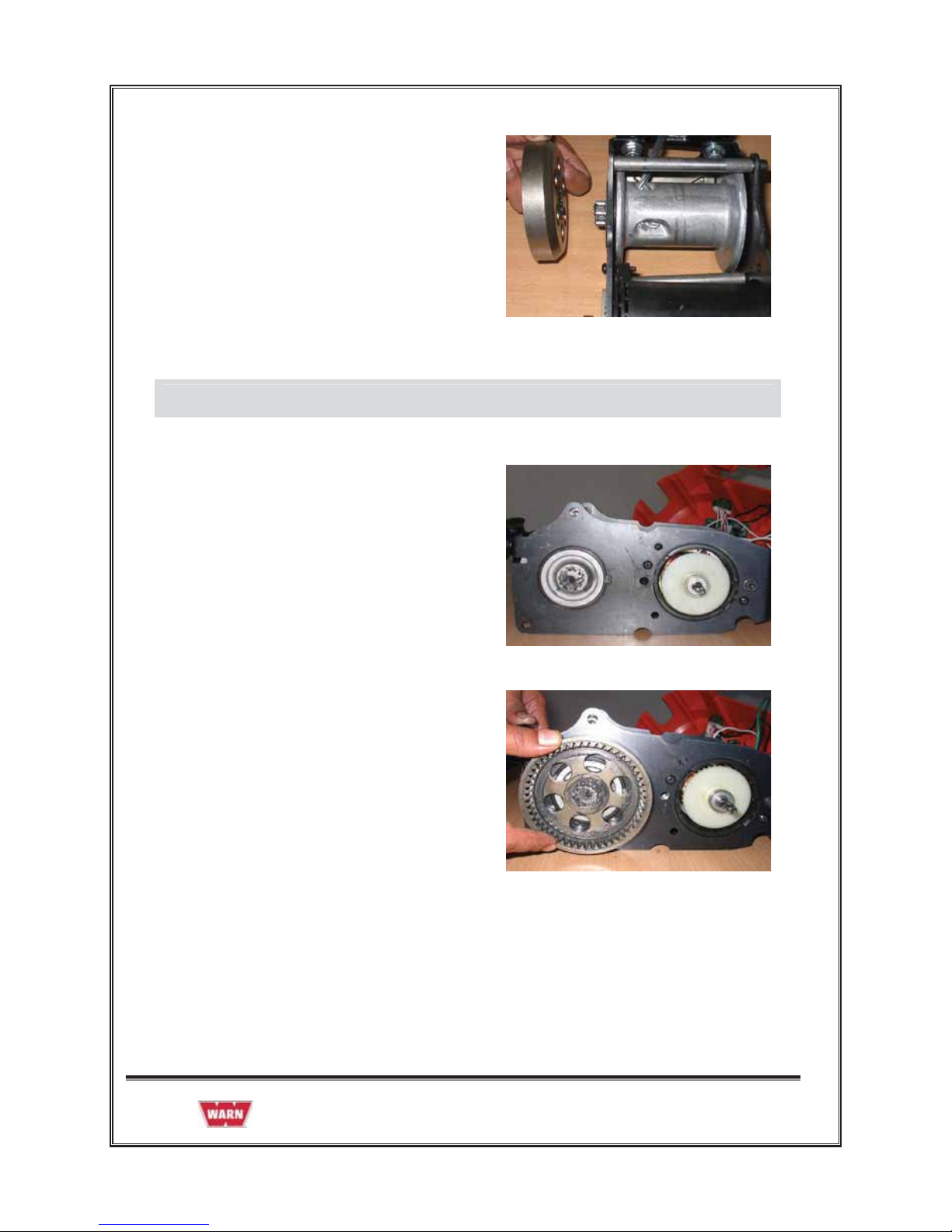
2.3.1 GEAR TRAIN ASSEMBLY REMOVAL
1. Remove Retaining Ring from Idler Gear
2. Remove Wear Washer from Idler Gear
3. Remove Retaining Ring from Helical
Gear . Remove Wear Washer from
Helical Gear.
987605A1 Page 12 of 49
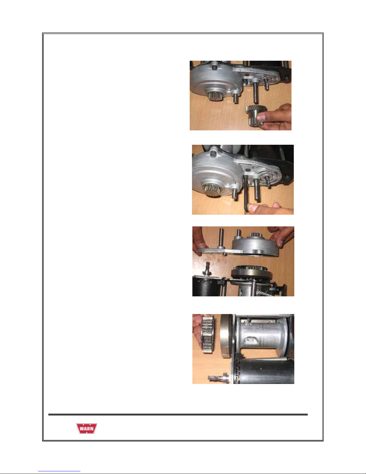
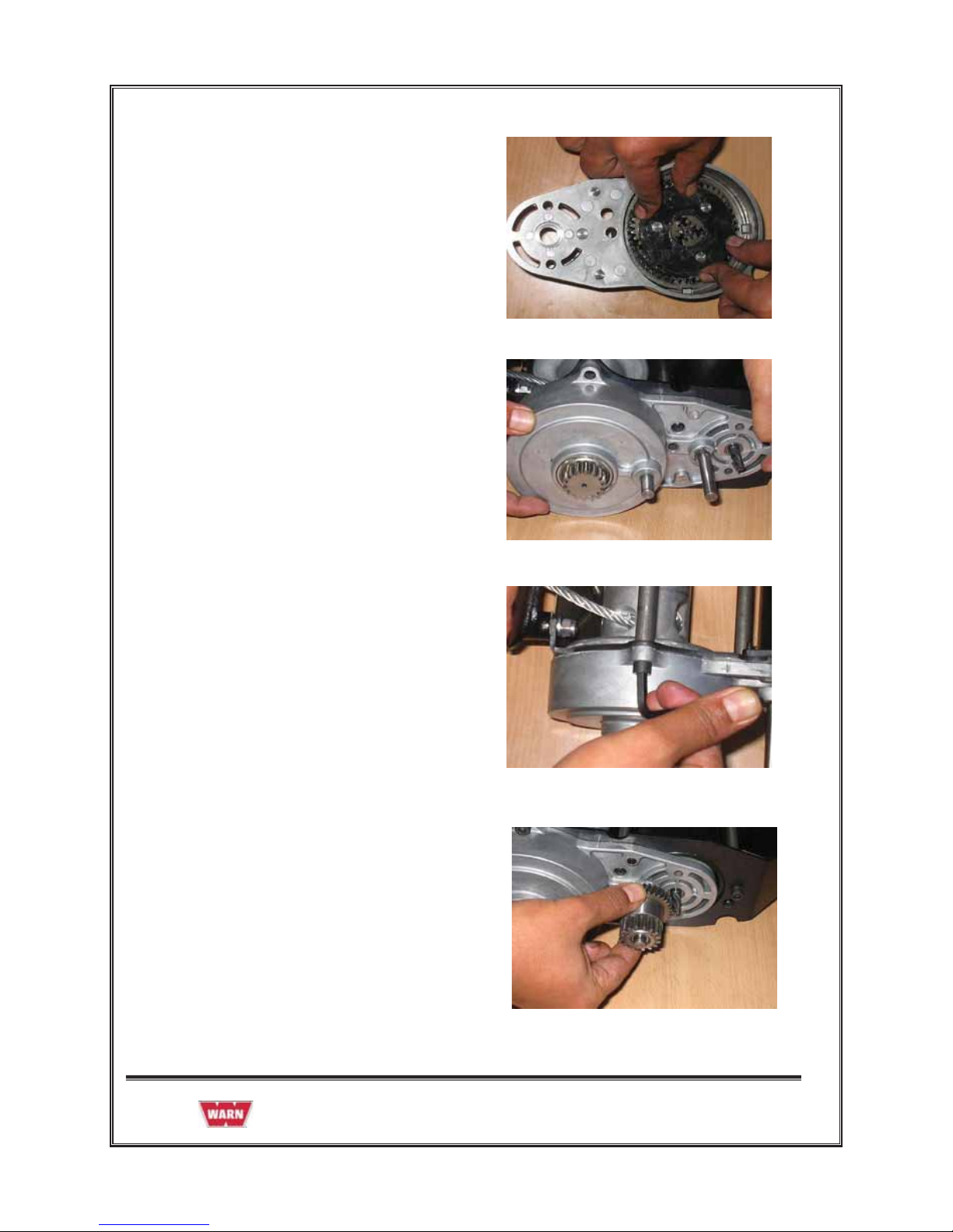
4. Remove Helical Gear from Gear
Housing.
5. Remove 3 Cap Screws (#3 x .75)
from Gear Housing through Left side
Bracket of Chassis assembly.
6. Remove Gear Housing from left side
Bracket of Chassis assembly.
7. Remove Carrier Assembly from Ring
Gear.
987605A1 Page 13 of 49
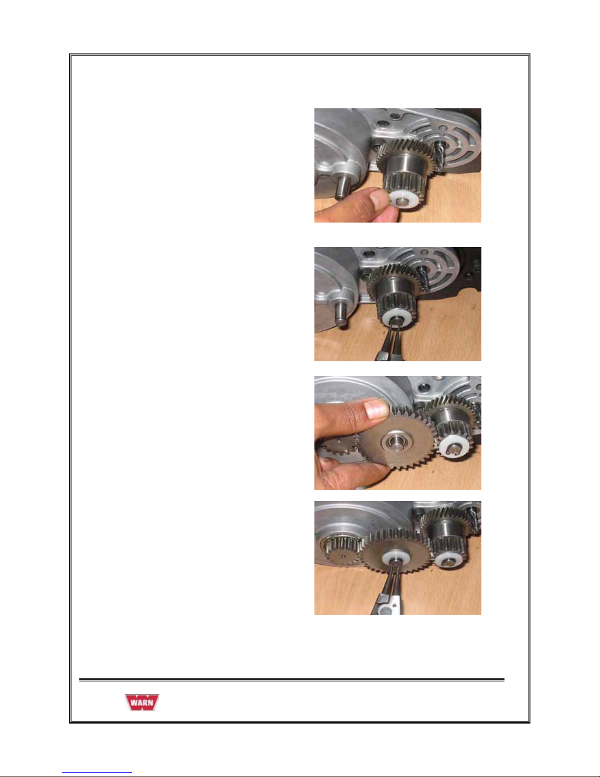
8. Remove Ring Gear 51 T from left side
Bracket of Chassis assembly.
2.3.2 GEAR TRAIN REASSEMBLY
1. Install Gear Train assembly after
installation of Motor assembly.
2. Insert Ring Gear 51 T on Left side
Bracket of Chassis assembly as shown
in the figure.
987605A1 Page 14 of 49
3. Install Ring Gear 48T and Carrier
Assembly in Gear Housing .
4. Install Gear Housing on Left side
Bracket of Chassis assembly.
5. Install 3 Cap Screws (#3 x .75) in Gear
Housing through Left side Bracket of
Chassis assembly.
6. Install Helical Gear Press on Gear
Housing as shown in the figure.
987605A1 Page 15 of 49
7. Install Wear Washer on Helical Gear
Press.
8. Install Retaining Ring on Helical
Gear Press.
9. Install Idler Gear on Gear Housing.
10. Install Wear Washer and Retaining
Ring on Idler Gear.
 Loading...