


FMT-30A/80A/150A/300A
FM Transmitter
User Manual
Released by Warner RF Center on Jun-10th-2011
FMT-XXX (Ver. 2.1) User Manual
----------------------------------------------------------------------------------------------
---------------------------------------------------------------------------------------------------------------
1
A BRIEF INTRODUCTION
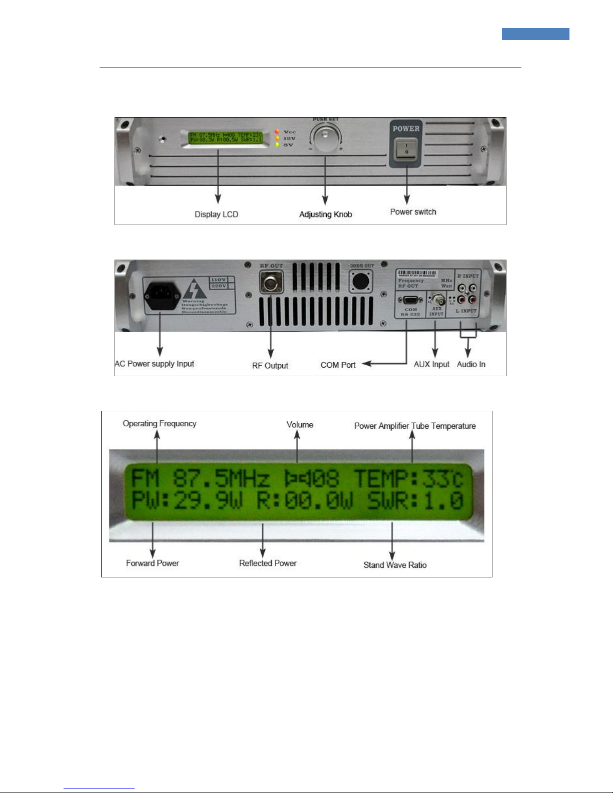
1. The front control panel as illustrated.
( Fig. 1)
2.The interfaces on the back as illustrated.
( Fig. 2)
3.The display interface as illustrated
( Fig. 3)
MAIN FEATURES
• Updated on FMT-30A (1U), the latest version (Ver2.1)
• Power adjustable: 0-30/80W/150W/300 watts.
• LCD displays operating frequency, volume, temperature, forward power, reflected power and
SWR.
• Single knob operation.
• Automatic power control maintaining the output at any preset level
• Pre-emphasis optional at 0, 50us or 75us.

FMT-XXX (Ver. 2.1) User Manual
----------------------------------------------------------------------------------------------
---------------------------------------------------------------------------------------------------------------
2
• Dual stereo audio input interface.
• Provided with SWR protection function and temperature protection, raise alarm prompts once
meet any trouble while working.
• Standard 19 inches, 2U whole aluminum case.
• Wiredrawing and oxidation makes surface bright, clean and elegant.
TECHNICAL SPECIFICATIONS
l Power Output: 30W/80W/150W/300W
l Frequency range: 87.5-108 MHZ
l Frequency tuning Step: 0.1MHZ
l Power step: 1W (30W, step 0.1W)
l Power Supply Voltage: AC100V-120V or AC220V-240V
l Stability of Frequency: ±10ppm ( -10 ℃ to +50 ℃ )
l Frequency Response: 50 - 15000Hz
l Signal to Noise Ratio: More than 50dB
l Distortion: less than 0.5%
l Parasitic amplitude modulation: Less than 0.2%
l Frequency deviation: Less than ±75KHz
l Modulation Mode: WFM
l Transmission Signal: FM Stereo and Mono
l Tuning Design: Stable PLL Technology
l Harmonic: More than 65dbc
l Audio Input Level: -15db Max: -30db
l Stereo Separation: More than 40db
l Operating time: True 24*7
l Antenna Connector: N Type (L16)
l Output Impedance: 50 ohm
l Audio Input Connector: RCA
l SCA/RDS Input Connector: BNC type
l Size of Transmitter Unit: 480mm * 200mm * 44mm (Standard 1U case)
OPERATING INSTRUCTIONS
IMPORTANT:
Prior to turning power on, hope you have fully been aware of the power supply voltage of the
transmitter. The transmitter has 110V or 220V available, we will switch to one of the voltages as you
requested, or switch to standard power supply voltage according to your location.
1. Connect your transmitter
Connect the antenna or dummy load to RF output port then connect the power supply.
2. Press the power button on the front control panel, the switch red indicator lights and the LCD
displays logo after 3 seconds (Fig.4) (Logo can be customized).
 Loading...