

Page 1
WWaarrnneerr IInnssttrruummeennttss
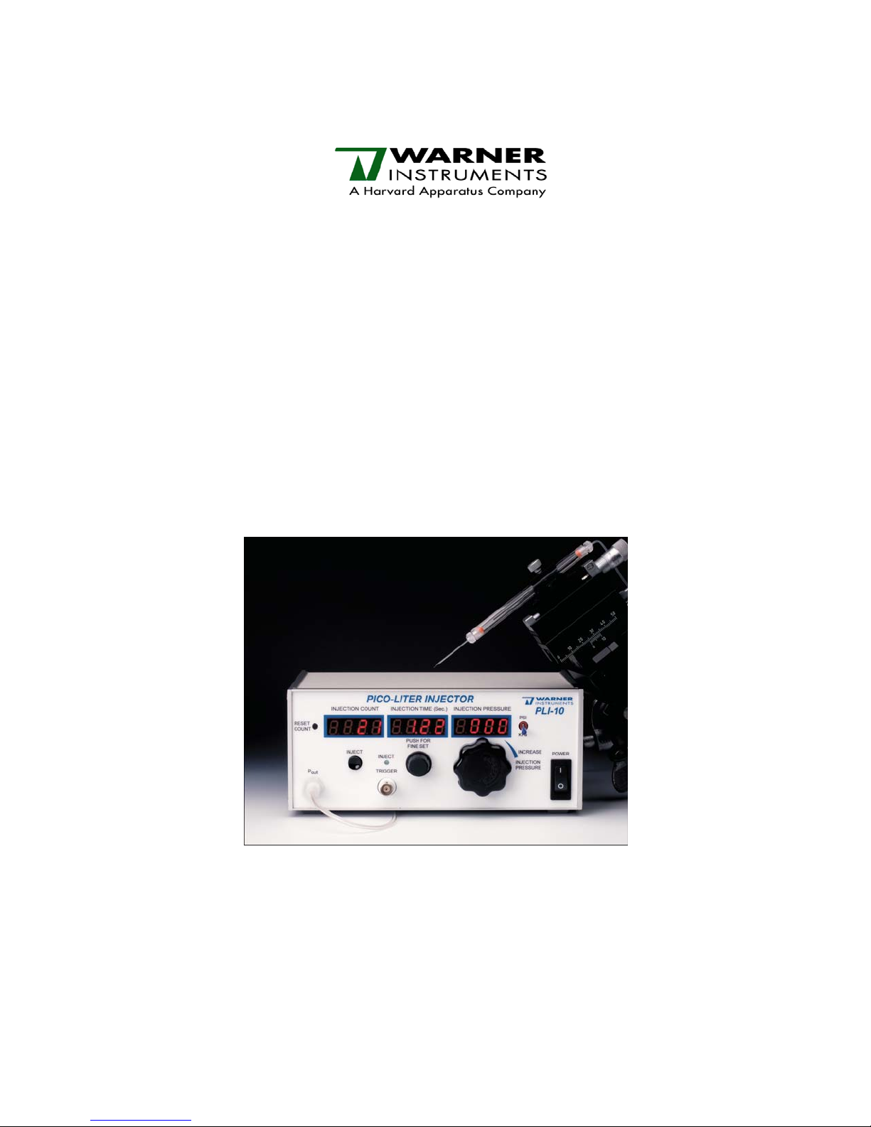
PPiiccoo--lliitteerr IInnjjeeccttoorr
MMooddeell PPLLII--110
0
Page 2

The PLI-10 Pico-liter Injector is designed to provide controlled delivery of picoliter to
nanoliter volumes of solution through a glass micropipette. The PLI-10 is ideal for
applications such as neuronal tract-tracing, delivery of pharmacological agents in vitro,
and Xenopus oocyte injection.
Features for the PLI-10 include
9 Low cost
2
9 Femtoliter to microliter injections
9 Digital readouts for injection pressure, time, and count
9 Reliable optically encoded circuit for injection time set
9 Easy to use
9 Same high quality pressure regulator as PLI-90 and PLI-100
THIS EQUIPMENT IS NOT DESIGNED NOR INTENDED
FOR USE ON HUMAN SUBJECTS
Warner Instruments • 1125 Dixwell Avenue, Hamden, CT 06514 USA
(203) 776-0664 • (800) 599-4203 • Fax (203) 776-1278
Rev 090714
Page 3

Table of Contents
NOMENCLATURE....................................................................................................................................4
Text conventions.....................................................................................................................................4
GENERAL...................................................................................................................................................5
Instrument description...........................................................................................................................5
FRONT AND BACK PANEL CONTROLS AND CONNECTIONS....................................................5
Front panel..............................................................................................................................................5
Rear panel ...............................................................................................................................................6
SETUP AND OPERATION.......................................................................................................................8
Setup........................................................................................................................................................8
Operation ................................................................................................................................................8
3
ADDITIONAL INFORMATION..............................................................................................................9
Required Auxiliary Equipment for Microinjection................................................................................9
Required Supplies..................................................................................................................................10
Optional Equipment for Microinjection...............................................................................................10
Micropipettes..........................................................................................................................................10
Distinguishing Parameters....................................................................................................................10
Choosing the Right Pipette....................................................................................................................10
General Considerations.........................................................................................................................11
Injection Pressure and Time Pulse.......................................................................................................12
Gas Usage Warning...............................................................................................................................12
Hose Connections..................................................................................................................................12
Volume Calibration Chart.....................................................................................................................13
APPENDIX................................................................................................................................................14
Specifications.........................................................................................................................................14
Ordering Information..........................................................................................................................14
Warranty and Service..........................................................................................................................15
Warranty.............................................................................................................................................15
Service................................................................................................................................................15
Certifications.........................................................................................................................................16
Warner Instruments • 1125 Dixwell Avenue, Hamden, CT 06514 USA
(203) 776-0664 • (800) 599-4203 • Fax (203) 776-1278
Rev 090714
Page 4

NOMENCLATURE
Text conventions
This manual refers to instrument controls at three functional levels; control blocks, specific controls
within a block, and settings of specific controls. To minimize the potential for confusion, we have
employed several text conventions which are specified below. Since our goal is to provide clarity rather
than complexity, we welcome any feedback you may wish to provide.
4
¾ Warner Instrument product numbers are presented using
¾ References to specific controls within a block are specified using
bold type.
SMALL CAPS.
¾ Finally, references to individual control settings are specified in italic type.
¾ Special comments and warnings are presented in highlighted text.
Any other formatting should be apparent from context.
Warner Instruments • 1125 Dixwell Avenue, Hamden, CT 06514 USA
(203) 776-0664 • (800) 599-4203 • Fax (203) 776-1278
Rev 090714
Page 5
5
GENERAL
Instrument description
The PLI-10 is specifically designed for solution delivery to extracellular locations in tissues and for
intracellular Xenopus oocyte injection. These ‘large volume’ injections (10 pl to greater than 100 pl) are
common for many applications that do not require multiple pressure settings. As such, the PLI-10 is an
effective, low-cost alternative to our more elaborate pressure ejection systems (e.g., the PLI-90 and PLI-
100).
Pressure to the micropipette is controlled precisely through a high-quality multi-turn regulator and is
reported digitally for reproducibility. Injection time is set using an optically encoded circuit which permits
fine and coarse settings from a single dial knob. The system trigger timer can be controlled by the front
panel push button, a foot switch, or an external trigger (TTL pulse to
TRIGGER INPUT BNC).
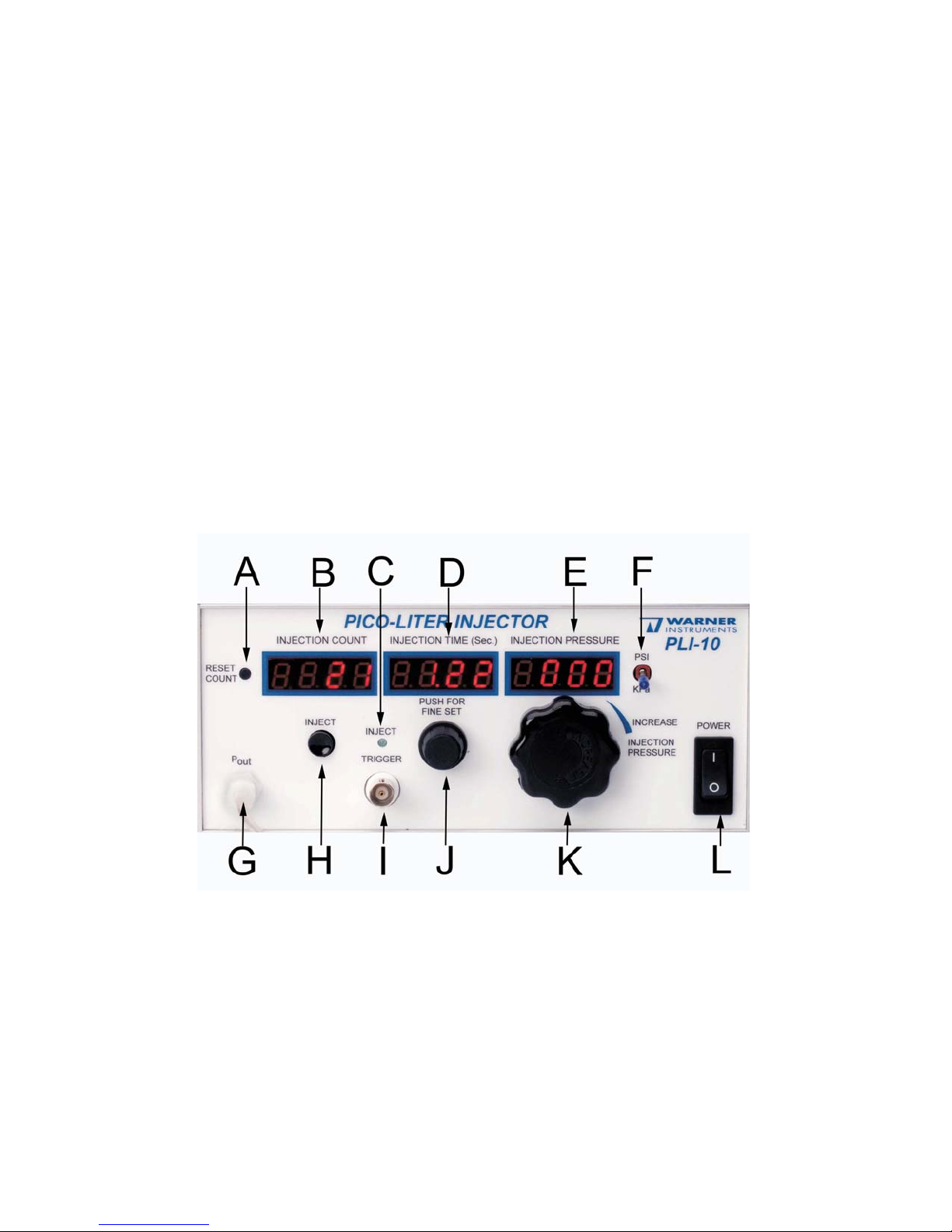
FRONT AND BACK PANEL CONTROLS AND CONNECTIONS
Front panel
A. RESET COUNT pushbutton: Resets the injection count display to zero.
B. INJECTION COUNT display: Records and displays the total number of injections triggered (0 to
9999 injections).
C. INJECT LED: LED indicator remains lit for duration of injection period.
D. INJECTION TIME (s): Displays injection time period in seconds (0 to 99.99 s)
Warner Instruments • 1125 Dixwell Avenue, Hamden, CT 06514 USA
(203) 776-0664 • (800) 599-4203 • Fax (203) 776-1278
Rev 090714
Page 6

E. INJECTION PRESSURE: Displays injection pressure in either PSI or kPa (maximum 60 PSI; 413
kPa).
F. PRESSURE UNIT toggle switch: Toggle switch controls injection pressure display unit of
measure. Injection pressure can be displayed in either pound-force per square inch (PSI) or
kilopascals (kPa).
G. PRESSURE OUTPUT (P
connects P
to injection pipette holder.
out
) connector: Pressurized gas output line. Output tubing line
out
H. MANUAL INJECTION TRIGGER: Press-button trigger delivers regulated pressure for the
digitally set period of time at the desired pressure.
I. EXTERNAL INJECTION TRIGGER INPUT BNC: This input is for electrically initiating injection
from an external trigger source. A positive TTL pulse of is required (baseline 0 V, trigger 5 V,
lasting >10 ms).
J. INJECTION TIME SETTING DIAL: This dial controls the injection time setting. Turning the dial
changes the injection time in seconds; pressing the dial in and turning changes the injection time
in fractions of a second.
K. INJECTION PRESSURE REGULATOR: This seven turn control sets the injection pressure over
the range from 0.2 to 60 PSI (1.4 to 413 kPa).
L. POWER switch: This switch turns the instrument on and off.
6
Rear panel
M. PRESSURE INPUT (P ) connector: This connector is the input for the compressed gas. 75 PSI
is the recommended input pressure; maximum input pressure is 105 PSI.
in
Warner Instruments • 1125 Dixwell Avenue, Hamden, CT 06514 USA
(203) 776-0664 • (800) 599-4203 • Fax (203) 776-1278
Rev 090714
Page 7

N. POWER INPUT connector: This connector is the input for the external power supply (9V DC @
400 mA; universal input voltage 90-264 VAC).
O. PRESSURE MONITOR OUTPUT BNC: This connector outputs the injection pressure (P
analog signal that can be directed to an external recording device. (10 mV/PSI or 1 mV/kPa).
P. REMOTE INJECT foot switch input connector: An optional foot switch (PLI-FS) can be
connected to the instrument. Pushing the foot switch triggers an injection for the preset time and
pressure values displayed on the instrument front panel.
) as an
out
7
Warner Instruments • 1125 Dixwell Avenue, Hamden, CT 06514 USA
(203) 776-0664 • (800) 599-4203 • Fax (203) 776-1278
Rev 090714
Page 8

SETUP AND OPERATION
The PLI-10 is provided with input and output hoses for gas handling and a foot switch for triggering
injections. Additional requirements include an acrylic pipette holder (see ordering information below) and
glass micropipettes. A regulated air/gas supply and a micromanipulator to hold the injection pipette are
needed to create a complete microinjection system. The setup and operation of the PLI-10 is
straightforward.
Setup
1. Connect the instrument to an electrical outlet using the 9V DC power supply input (Item N).
2. Attach one end of the input hose to a regulated air/gas supply and use the quick-clip connector to
connect the input hose to P
(Item M) on the back of the instrument.
in
8
3. Connect the output hose to the instrument P
(Item G) using the quick-clip connector. Attach the
out
other end of the output hose to the pipette holder. Position and secure the pipette holder into a
micromanipulator.
4. Turn the unit on (Item L). The three LED displays (Items B, D, and E) will illuminate.
5. Press the
RESET COUNT button (Item A) to reset the injection count display (Item B) to zero, if
necessary.
6. Turn the
SET DIAL
7. Turn the
E). Pressure can be set and monitored in units of PSI or kPa, set by the
TIME SET DIAL (Item J) to the desired injection time (displayed in Item D). Pressing the TIME
in and turning will allow fine adjustment of injection time in tenths of seconds.
INJECTION PRESSURE set knob (Item K) to set the desired injection pressure (displayed in Item
TOGGLE SWITCH (Item F). If
the desired pressure is unknown, it can be determined by observing a loaded micropipette under a
microscope. Gradually increase injection pressure setting until solution is flowing from the
micropipette tip.
8. Optional remote triggering of an injection can be achieved using a footswitch or TTL pulse. Insert the
footswitch plug into the
Similarly, an analog 5V TTL input to the BNC
REMOTE INJECT jack (Item P). Pressing the footswitch triggers an injection.
TRIGGER (Item I) can be used to trigger an injection from
an external device (such as a digital acquisition system).
9. Optional monitoring/recording of injection pressure settings can be achieved by the analog
signal output (Item O). This output is calibrated to 10 mV/PSI or 1 mV/kPa.
Operation
10. The assembled system is ready to use. Turn on the air/gas supply at the source, and slowly increase
the outflow regulator to the desired pressure setting.
NOTE: The input pressure should be at least 7 PSI higher than the desired working/injection pressure
for the pneumatic components to operate properly.
Warner Instruments • 1125 Dixwell Avenue, Hamden, CT 06514 USA
PRESSURE
(203) 776-0664 • (800) 599-4203 • Fax (203) 776-1278
Rev 090714
Page 9

11. Turn the instrument on, and set the injection pressure and injection time to the desired values. The
P
tubing line should remain unattached to the control unit at this time to prevent any latent
OUT
pressure from building up in the micropipette.
12. Backfill the micropipette with a desired volume of the compound to be injected. Microfill-style syringe
tips can be used to fill the micropipette and avoid solution contaminating the outside of the
micropipette.
13. Insert micropipette into the pipette holder and secure it into place by tightening the acrylic screw.
9
14. Attach the P
tubing line to the connector on the control unit.
OUT
15. Position the micropipette to the location where the injection bolus is to be delivered. This often
requires a micromanipulator.
16. Trigger an injection by pressing the inject button (Item H). Alternatively, an external trigger or
footswitch can be used to trigger an injection.
17. After injection is complete, the micropipette should be disposed of in an appropriate “sharps
container”. For tract-tracing studies, using a fresh micropipette for each injection is advised. A single
pipette can be used to serially inject multiple oocytes with the same compound if the micropipette tip
remains undamaged.
18. Upon completion of the experiment, remove the pipette from the holder and power the unit off. The
air/gas input should also be turned off at the source.
ADDITIONAL INFORMATION
Note: The following material is excerpted from the user’s manuals for the PLI-90 and PLI-100.
These manuals are available for download on our website for your reference.
Microinjection also involves other skills, several other instruments and accessories, and
various supplies. The purpose of this section is to give an overview of these techniques for those
new to microinjection. Some guidance on equipment selection is also supplied.
Required Auxiliary Equipment for Microinjection
The required equipment includes a pipette puller and micromanipulator(s). Ideally, the puller
should be capable of making pipettes with tip diameters in the 0.2 to 1.57 micron range with a
short enough taper length for both mechanical strength and low flow resistance. If most injections
are to be extracellular, then a puller suitable for extracellular patch clamp pipettes is satisfactory.
For intracellular injections, some magnetic pullers may be suitable. Alternatively, a two stage
gravity puller with variable weights can be satisfactory over the entire range. The required three
dimensional movements of the injection pipette can be produced by an inexpensive mechanically
linked micromanipulator for large cells such as frog oocytes.
Warner Instruments • 1125 Dixwell Avenue, Hamden, CT 06514 USA
(203) 776-0664 • (800) 599-4203 • Fax (203) 776-1278
Rev 090714
Page 10

10
Required Supplies
These are compressed gas and glass capillary tubes. Compressed air is suitable for oxygen-
insensitive injection material. Nitrogen is a satisfactory inert gas for the general case. An input
pressure of 105 psi is sufficient: a regulator will be needed if supplied from a bottle of
compressed gas.
Optional Equipment for Microinjection
This includes a microforge (to bend a micropipette or to polish a pipette tip for holding a cell),
a microgrinder (to bevel the pipette tip to increase the delivery rate without additional cell
damage), and a microincubator (to hold the cells at incubation temperature during microinjection).
Micropipettes
The micropipettes are made by pulling a glass capillary (1-2 mm. outer diameter) by heating
some 3-10 mm. of its length with a concentric heater while applying a force (gravitational or
magnetic) to pull both ends of the capillary apart. Two micropipettes are produced per capillary.
Distinguishing Parameters
Two useful distinguishing parameters of the micropipette are the inside diameter of the tip
and the angle of taper to the tip. For a single-stage puller, a smaller taper angle will yield a
longer tapered region. The larger the tip, the more material is delivered for the same applied
pressure and time. Just a 10% decrease in diameter decreases the delivery rate by over 30%. A
10% decrease in taper angle (longer taper) would decrease the delivery rate about 10%. The
extreme sensitivity of delivery rate on tip diameter makes it important to have a reproducible
pipette puller. If you use published tip sizes as a starting point, distinguish between the relevant
inside diameter and the more visible outside diameter. (The ratio of the two is the same at the tip
as for the original capillary glass.)
Choosing the Right Pipette
Choosing a pipette size and shape for intracellular injection is difficult. Larger tips deliver
more material but increase the risk of cell damage caused by leakage around the pipette while in
the cell or later by incomplete sealing. The smaller the cell, the smaller the pipette tip that is
required. The smaller the tip, the more likely it is to clog.
For reference, intracellular electrophysiologists routinely record for an hour or so from cells of
10 micron diameter with pipette tips of 0.1 micron inside diameter. Larger tips can therefore be
used for brief injection in such cells. For nuclear injections, a smaller taper angle is needed to
avoid leakage further up the shank of the pipette at the plasma membrane.
Although even intracellular injection can be done from below with an upright microscope,
most injections are done from the side or from above the cells. Different strategies have been
used to suitably fix the cell in position for successful intracellular injection:
Warner Instruments • 1125 Dixwell Avenue, Hamden, CT 06514 USA
(203) 776-0664 • (800) 599-4203 • Fax (203) 776-1278
Rev 090714
Page 11

11
1. for suspended cells, a second, larger pipette is used to hold the cell. This pipette’s tip is
first polished with a microforge (done by placing the pipette within 5 microns of a hot filament for
a few seconds).With its axis horizontal, it is moved to hold the cell with applied suction. The
injection pipette is also straight and is inserted horizontally from the opposite side. This geometry
avoids damage to the cell membrane caused by shearing forces. The optics are straightforward
because the pipettes remain in focus as they are advanced.
2. for cells that can be or are attached to a surface in a closely packed layer, straight
injection pipettes can also be used. In this case, the pipette axis slopes slightly down from the
horizontal. The tendency of the cells to slide when the pipette enters is resisted by the
extracellular environment or attachment to the culture surface. The microscope should be focused
on the cell’s surface. The pipette tip then comes into focus just before injection. If the cell is nearly
spherical (the hardest case), the pipette should again enter the cell membrane at right angles to
avoid shearing. Non-spherical cells (for example, cultured fibroblasts) have a more robust
cytoskeletal structure so the pipette can be pushed in even if not perpendicular to the membrane
surface.
3. for less firmly attached cells, the injection pipette can be bent near the tip after pulling.
The pipette’s main axis slopes slightly down from the horizontal. The angle of bend should allow
the tip to point straight down. With an inverted microscope, the tip is viewed through the cell as it
is lowered for injection. The microscope is focused on the cell’s top surface and the tip comes into
focus just before insertion. Again, shearing forces are avoided. Suitable bends can be made with
a microforge: a simple way to do this is to move the pipette near a hot filament at the position of
desired bend. The tip will spontaneously bend away.
In all of the above techniques, a three dimensional micromanipulator controls the movement
of the injection pipette. If this (straight) pipette is instead attached to a condenser mount (inverted
scope), then a one dimensional manipulator can be used. The remaining two directions of
manipulation are done with stage micrometers moving the vertical injection pipette over each cell
in turn. If the vibrations transmitted with the condenser mounting are manageable, then this
approach gives the fastest rate of cell injection.
General Considerations
It is much easier to reliably inject large volumes than small ones. For “large” volumes, a
balance pressure capability is not needed. The dividing line between large and small is not rigid:
it depends on how quantitative a delivery is required. That volume line would typically be in the
10-100 picollier range. (For convenient visualization and approximate geometric measurement, 1
femtoliter is a cube 1 micron on a side or a sphere 1.24 microns in diameter, 1 picoliter is a cube
10 microns on a side or a sphere 12.4 microns in diameter, while 1 nanoliter is a cube 100
microns on a side or a sphere 124 microns in diameter. Because volume goes as the cube of
linear dimensions, such geometric volumes are imprecise, but often useful). Extracellular delivery
is nearly always “large”. Intracellular injection is often of “small” volumes (but not for frog
oocytes).
Warner Instruments • 1125 Dixwell Avenue, Hamden, CT 06514 USA
(203) 776-0664 • (800) 599-4203 • Fax (203) 776-1278
Rev 090714
Page 12

12
Filling of the injection pipette can be done from the back end (barrel) of the pipette using a
syringe with a thin hypodermic needle or “microfil” tip inserted so its tip is down in the tapered
section. If the capillary has a filling fiber attached to the inner wall the pipette tip will then fill by
capillary action without air bubbles, at least for larger tips. Variations on this procedure involve
filling a smaller capillary first and inserting it for the back fill.
Injection Pressure and Time Pulse
Setting the initial injection pressure low prevents the loss of solution. To easily obtain the
desired pressure setting, set the time pulse on (1) one second with the injection pressure set at its
minimum. Trigger the time pulse while viewing under magnification.
Increase the injection pressure until the solution within the pipette begins to flow out the tip
opening. The pressure shown on the LCD can now be used as the initial injection pressure
setting. Adjust the injection pressure and timing to obtain the desired injection.
Gas Usage Warning
To provide finely controllable output pressure, the gas regulators are of the “bleeding” type.
Such regulators use gas even in the absence of ejections. The Pico-Injector thus uses gas even
when off. To eliminate this consumption and as a good safety practice, turn off the gas supply at
the source when the Pico-Injector is not in use.
Hose Connections
The input and output hoses should be attached to their respective connectors. If each
connector’s needle valve, located in the micro-injector body, is not fully opened, the airflow will be
restricted or blocked. To prevent this from happening, check each connector for tightness by
turning clockwise. This will ensure needle valve depression.
Warner Instruments • 1125 Dixwell Avenue, Hamden, CT 06514 USA
(203) 776-0664 • (800) 599-4203 • Fax (203) 776-1278
Rev 090714
Page 13

Volume Calibration Chart
Formula: Volume in nanoliters = .17952 x tip ID3 (in μm) x PSI x time (in sec)
13
3
x (10) x (1) = 224.4 nanoliters
Pressur
e (p.s.i.)
Example: Volume = .17952 x (5)
Time
(sec.)
Pipette Tip
I.D. (μm)
Femtoliters Picoliters Nanoliters Microliters Milliliters
1 1 0.1 179.52 0.18 - - 10 1 0.1 1795.20 1.80 - - 20 1 0.1 3590.40 3.59 - - 30 1 0.1 5385.60 5.39 - - 40 1 0.1 7180.80 7.18 - - 50 1 0.1 8976.00 8.98 - - 60 1 0.1 10771.20 10.77 - - -
1 1 1 - 179.52 0.18 - 10 1 1 - 1795.20 1.80 - 20 1 1 - 3590.40 3.59 - 30 1 1 - 5385.60 5.39 - 40 1 1 - 7180.80 7.18 - 50 1 1 - 8976.00 8.98 - 60 1 1 - 10771.20 10.77 - -
1 1 5 - - 22.44 0.02 10 1 5 - - 224.40 0.22 20 1 5 - - 448.80 0.45 30 1 5 - - 673.20 0.67 40 1 5 - - 897.60 0.90 50 1 5 - - 1122.00 1.12 60 1 5 - - 1346.40 1.35 -
1 1 10 - - 179.52 0.18 10 1 10 - - 1795.20 1.80 20 1 10 - - 3590.20 3.59 30 1 10 - - 5385.60 5.39 40 1 10 - - 7180.80 7.18 50 1 10 - - 8976.00 8.98 60 1 10 - - 10771.20 10.77 -
1 1 75 - - - 75.74 0.08
10 1 75 - - - 757.35 0.76
20 1 75 - - - 1514.70 1.51
30 1 75 - - - 2272.05 2.27
40 1 75 - - - 3029.40 3.03
50 1 75 - - - 3786.75 3.79
60 1 75 - - - 4544.10 4.54
Warner Instruments • 1125 Dixwell Avenue, Hamden, CT 06514 USA
(203) 776-0664 • (800) 599-4203 • Fax (203) 776-1278
Rev 090714
Page 14

APPENDIX
Specifications
14
Input Gas Pressure:
75 PSI Recommended, 105 PSI Maximum
(≥7 PSI above injection pressure)
Injection Pressure: 0.2 to 60 PSI (413 KPa) regulated
Injection Time: 0.01 to 99.99 Seconds
Injection Time Accuracy: ±0.01% (Crystal Time Base)
Pressure Display: 3½ Digits, 0.1 PSI or 1 kPa Resolution
Injection Count Display: 0 to 9999 Injections
Trigger Mode: Front Panel, Footswitch, TTL (Gate In)
Pressure Monitor: Output BNC, Rear Panel, 10 mV/PSI or 1 mV/KPa
Power Input: External 9VDC @ 400mA (min)
Power Supply universal input voltage 90 to 264 VAC
Weight: 2.3 kg
Dimensions:: 89 x 215 x 175 mm (H x W x D)
Warranty: One year, parts & labor
Ordering Information
64-1707 PLI-10
64-1626 AO161.0 Acrylic pipette holder for 1.0 mm pipettes
64-1627 AO161.2 Acrylic pipette holder for 1.2 mm pipettes
64-1628 LPLI-PPH Acrylic pipette holder for 1.5mm pipettes
64-1629 AO162.0 Acrylic pipette holder for 2.0mm pipettes
65-0008 PLI-IHN Gas Input Hose
65-0010 PLI-OHN Gas Output Hose
Warner Instruments • 1125 Dixwell Avenue, Hamden, CT 06514 USA
Model
number
Pico-liter injector (includes input hose, output hose, and
footswitch)
(203) 776-0664 • (800) 599-4203 • Fax (203) 776-1278
Rev 090714
Description Order number
Page 15

Warranty and Service
Warranty
The PLI-10 Pico-liter Injector is covered by our Warranty to be free from defects in materials and
workmanship for a period of one year from the date of shipment. If a failure occurs within this period,
we will either repair or replace the faulty component(s). This warranty does not cover failure or
damage caused by physical abuse.
In the event that repairs are necessary, shipping charges to the factory are the customer's
responsibility. Return charges will be paid by Warner Instruments.
Service
We recommend that all questions regarding service be referred to our Technical Support
Department.
• Normal business hours are 8:30 AM to 5:00 PM (EST), Monday through Friday.
• We are located at 1125 Dixwell Avenue, Hamden, CT 06514.
• We can be reached by phone at (800) 599-4203 or (203) 776-0664. Our fax number is
(203) 776-1278.
15
• We can be emailed at support@warneronline.com or through the contact section of our website
http://www.warneronline.com.
at
IMPORTANT - CUSTOMERS OUTSIDE OF THE U.S.: Please be sure to contact us before return
shipping any goods. We will provide instructions so that the shipment will not be delayed or subject
to unnecessary expense in clearing U.S. Customs.
Warner Instruments • 1125 Dixwell Avenue, Hamden, CT 06514 USA
(203) 776-0664 • (800) 599-4203 • Fax (203) 776-1278
Rev 090714
Page 16

Certifications
Application of Council Directive: 89/336/EEC
Standards To Which
Conformity Is Declared:
Declaration of Conformity
CE MARKING (EMC)
EN55022 Class A
EN61000-3-2
EN61000-3-3
EN50082-1:1992
EN61000-4-2
EN61000-4-3
ENV50204
EN610000-4-4
EN610000-4-8
EN610000-4-11
16
Manufacturer’s Name:
Warner Instruments, LLC
Manufacturer’s Address: 1125 Dixwell Avenue
Hamden, CT 06514
Tel: (203) 776-0664
Equipment Description:
Pico-liter injector
Equipment Class: ITE-Class A
Model Numbers: PLI-10
I the undersigned, hereby declare that the equipment specified
above, conforms to the above Directive(s) and Standard(s).
Place: Hamden, Connecticut
USA
Signature:
Full Name: Ralph Abate
Warner Instruments • 1125 Dixwell Avenue, Hamden, CT 06514 USA
Position: General Manager
(203) 776-0664 • (800) 599-4203 • Fax (203) 776-1278
Rev 090714
Page 17

Application of Council Directive: 73/23/EEC
Standards To Which
Conformity Is Declared:
17
Declaration of Conformity
CE MARKING (LVD)
EN61010-1:2001
Manufacturer’s Name:
Warner Instruments, LLC
Manufacturer’s Address: 1125 Dixwell Avenue
Hamden, CT 06514
Tel: (203) 776-0664
Equipment Description:
Pico-liter injector
Safety requirements for
electrical equipment for
laboratory use
Equipment Class: Class I
Model Numbers: PLI-10
I the undersigned, hereby declare that the equipment specified
above, conforms to the above Directive(s) and Standard(s).
Place: Hamden, Connecticut USA
Signature:
Warner Instruments • 1125 Dixwell Avenue, Hamden, CT 06514 USA
Full Name: Ralph Abate
Position: General Manager
(203) 776-0664 • (800) 599-4203 • Fax (203) 776-1278
Rev 090714
Page 18

18
18
Warner Instruments • 1125 Dixwell Avenue, Hamden, CT 06514 USA
Warner Instruments • 1125 Dixwell Avenue, Hamden, CT 06514 USA
(203) 776-0664 • (800) 599-4203 • Fax (203) 776-1278
(203) 776-0664 • (800) 599-4203 • Fax (203) 776-1278
Rev 090714
Rev 090714
 Loading...