

Page 1
BC-535 Preliminary, Rev. 060126
WWaarrnneerr IInnssttrruummeennttss
BBiillaayyeerr CCllaammpp AAmmpplliiffiieerr
MMooddeell BBC
C--553355
Warner Instruments
1125 Dixwell Avenue, Hamden, CT 06514
(800) 599-4203 / (203) 776-0664
(203) 776-1278 - fax
Page 2

BC-535 Preliminary, Rev. 060126
TTaabbllee ooff CCoonntteenntts
s
NOMENCLATURE....................................................................................................................................5
Text conventions.....................................................................................................................................5
Device panel abbreviations....................................................................................................................5
CONTROL DESCRIPTION......................................................................................................................6
Front panel..............................................................................................................................................6
Hold......................................................................................................................................................6
Offset ....................................................................................................................................................7
Meter ....................................................................................................................................................7
Outputs.................................................................................................................................................8
Capacitance compensation...................................................................................................................8
Power ...................................................................................................................................................9
Rear panel ...............................................................................................................................................9
Headstage.............................................................................................................................................9
Circuit and chassis grounds.................................................................................................................9
Gain Telegraph ..................................................................................................................................10
Filter Telegraph .................................................................................................................................10
Im output ............................................................................................................................................11
External Command In ........................................................................................................................11
Capacitance Output............................................................................................................................11
Cap Sync Out......................................................................................................................................11
External speaker.................................................................................................................................11
ADDITIONAL INFORMATION............................................................................................................11
Headstage connections .........................................................................................................................11
Model membrane..................................................................................................................................12
SETUP........................................................................................................................................................13
Basic design...........................................................................................................................................13
Faraday cage......................................................................................................................................13
Vibration isolation..............................................................................................................................14
Membrane support .............................................................................................................................14
Amplification......................................................................................................................................15
Filtering..............................................................................................................................................15
Acquisition hardware and software ...................................................................................................16
Data analysis......................................................................................................................................16
Data archival......................................................................................................................................16
Stirring ...............................................................................................................................................16
Page 3

BC-535 Preliminary, Rev. 060126
Perfusion ............................................................................................................................................17
Oscilloscope .......................................................................................................................................17
INITIAL TEST..........................................................................................................................................18
Amplifier setup .....................................................................................................................................18
Overview................................................................................................................................................18
Initial conditions...................................................................................................................................18
Hold voltage test.................................................................................................................................19
Input noise test without model membrane..........................................................................................20
Input noise test with model membrane...............................................................................................20
Test instrument Im output....................................................................................................................21
Cap test...............................................................................................................................................21
Autozero .............................................................................................................................................21
Capacity compensation ......................................................................................................................22
OPERATION ............................................................................................................................................23
Setup of the bilayer chamber...............................................................................................................23
Input offset............................................................................................................................................24
Input offset adjustment .......................................................................................................................24
Bilayer formation..................................................................................................................................24
Commands.............................................................................................................................................25
APPENDIX................................................................................................................................................26
Theoretical considerations...................................................................................................................26
Shielding .............................................................................................................................................26
Grounding ..........................................................................................................................................26
Membrane capacitance calculations...................................................................................................28
Suggested References ...........................................................................................................................29
Specifications.........................................................................................................................................30
Chloriding electrodes ...........................................................................................................................32
Techniques for chloriding silver wires................................................................................................32
Accessories and replacement parts.....................................................................................................33
Warranty...............................................................................................................................................33
Service....................................................................................................................................................33
Service notes.......................................................................................................................................33
Certifications.........................................................................................................................................35
Glossary.................................................................................................................................................38
Page 4

BC-535 Preliminary, Rev. 060126
The Warner BC-535 Bilayer Clamp Amplifier is a resistive-feedback voltage clamp amplifier
designed specifically for applications using planar lipid bilayer membranes. The unique circuitry and
dedicated design of this amplifier allows Warner to present an instrument of broad capability and
superior quality at a cost significantly below that of our competitors.
The operational range of the
BC-535 has been enhanced by the introduction of dual feedbackresistor circuitry within the headstage. This enhancement allows the amplifier to comfortably pass
currents of up to 2 nA while preserving the sub-pA sensitivity of the instrument. In addition, the range
of the digital hold control has been extended to 400 mV for internally generated commands and the
amplifier supports up to 1 V at the external command input, for a sum capability of 1400 mV hold
potential.
The remaining functionality of the BC-353 is built on the renown capabilities of the BC-525D and
includes junction potential auto-zeroing, a unique multi-step, digital hold potential circuit, audio
monitoring of membrane formation, and direct readout of the membrane capacitance.
Features of the BC-353 include
9 Dedicated design for bilayer applications
9 Digital, multi-step hold potential control
9 Hold potentials to ±1400 mV
9 Currents to ±2000 pA
9 Input offset with Auto-Zero
9 Direct membrane capacitance measurement
9 Low-pass 4-pole Bessel filter
9 Audio output
9 Capacitance compensation circuitry
THIS EQUIPMENT IS NOT DESIGNED NOR INTENDED
FOR USE ON HUMAN SUBJECTS
Page 5

BC-535 Preliminary, Rev. 060126 5
NOMENCLATURE
Text conventions
This manual refers to amplifier controls at three functional levels; control blocks, specific controls
within a block, and settings of specific controls. To reduce confusion, we have employed several text
conventions which are specified below. Since our goal is to provide clarity rather than complexity, we
welcome any feedback you may wish to provide.
¾ Warner Instrument product numbers are presented using
¾ References to instrument panel control blocks are specified using
¾ References to specific controls within a block are specified using
bold type.
UNDERLINED SMALL CAPS.
NON-UNDERLINED SMALL CAPS.
¾ Finally, references to individual control settings are specified in italic type.
¾ Special comments and warnings are presented in highlighted text.
Any other formatting should be apparent from context.
Device panel abbreviations
The BC-353 has several abbreviations on the front panel. They are listed here for quick
reference. In addition, these and other terms are collected and incl uded in a Glossary at the back of
this manual.
Term Meaning Section
Vc command voltage METER, OUTPUTS
Im output current METER, OUTPUTS
CMD IN commend in
CAP TEST capacitance test METER
CAP COMP capacitance compensation CAP COMP
Warner
A Harvard Apparatus Company .
Instruments
Page 6
BC-535 Preliminary, Rev. 060126 6
CONTROL DESCRIPTION
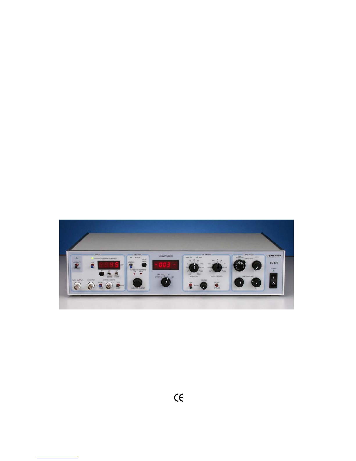
The instrument front panel is divided into six control blocks titled HOLD, OFFSET, METER, OUTPUTS,
CAP COMP, and POWER. The instrument rear panel has BNC connectors for the GAIN and FILTER
, I
TELEGRAPHS
connector (for the headstage), a 15 pin D connector, binding posts for
OUTPUT, CAP SYNC, MEMBRANE CAPACITANCE, and EXTERNAL COMMAND IN. A 9-pin DIN
M
CIRCUIT and CHASSIS GROUND,
and a SPEAKER OUTPUT are also located on the rear panel.
Front panel
Hold
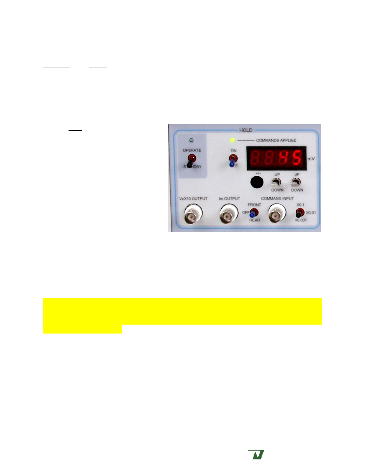
The HOLD block contains a meter and
controls for the application of internal or
external V
The appropriate membrane holding
potential is achieved by summing the
selected
external) with the
which results in a corrected transmembrane
voltage. An LED indicates
APPLIED to the headstage.
HOLD commands.
m
HOLD voltages (internal plus
INPUT OFFSET voltage
COMMANDS
The internal
HOLD control is comprised
of a digital circuit providing discrete
adjustment of the command potential. Two toggle switches directly below the
COMMANDS APPLIED
meter are used to step the applied command by ± 10 or ± 1 mV, respectively. A black push button is
used to quickly swap the polarity of the applied holding potential. The maximum range for this control
±
400 mV.
is
The internally generated
ON/OFF TOGGLE SWITCH to the right of the meter.
HOLD command can be disabled by selecting the off position on the
Note: The METER will still display the programmed hold voltage when the ON/OFF TOGGLE SWITCH is
selected to off. However, the programmed command will not be applied and the COMMANDS APPLIED
LED will remain unlit. This feature allows the user to select or change the holding potential wi thout
applying it to the membrane.
The V
This output reports the sum of potentials from V
x 10 OUTPUT monitors the voltage command applied to the headstage mul tiplied by 10.
c
HOLD, CMD IN, and PULSE GENERATOR. Connection is
m
made via BNC’s located on both the front and rear panels of the amplifier.
The I
output BNC’s are located on both the front and rear panels of the instrument.
I
m
External commands are applied to the amplifier via the
on both the front and rear panels. The
OUTPUT reports the membrane current modified by ampli fier gain and/or internal filtering.
m
COMMAND INPUT BNC connectors located
FRONT/REAR TOGGLE SWIT CH either disables all external input or
selects the location for command inputs. Selectable attenuation values are x0.1, x0.01, or x0.001.
Externally generated
COMMAND INPUTS are summed with the internally generated HOLD voltage.
Warner
A Harvard Apparatus Company .
Instruments
Page 7
BC-535 Preliminary, Rev. 060126 7
Offset
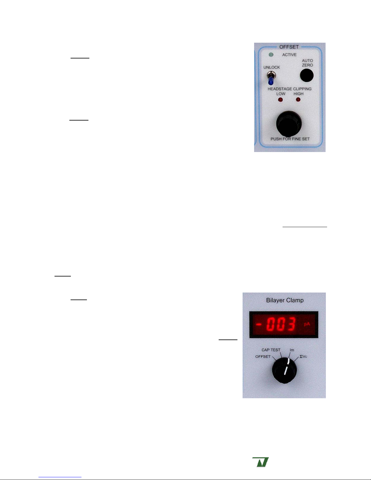
The OFFSET block contains the INPUT OFFSET and the AUTO-ZERO
controls.
The
INPUT OFFSET section is comprised of a rotary potentiometer with
low/high LED’s, the
ACTIVE LED. This section is used to compensate for junction potentials
produced by dissimilar solutions or other electrode potential differences.
The OFFSET circuit (AUTO-ZERO and OFFSET CONTROL) must be armed
prior to use. Thi s is achieved by use of the
of the momentary-on style and is operated by an upward movement.
When the circuit is armed the
can then be easily achieved by use of the
POTENTIOMETER. The circuit can be disarmed by a second movement of the UNLOCK TOGGLE.
The
AUTO-ZERO control provides the most direct means for setting the junction potential. When
armed, pressing the pushbutton initiates a cycle wherein the amplifier searches for and sets the offset
potential. The offset circuit is automatically disarmed at the completion of the cycle. Cycle time is
approximately 1 s.
AUTO-ZERO pushbutton, the UNLOCK toggle, and an
UNLOCK TOGGLE. This toggle is
ACTIVE LED will be lit. Offset adjustments
AUTO-ZERO control or ROTARY
ROTARY POTENTIOMETER is used to provide manual adjustment of up to ±120 mV at the
The
headstage input. Manual adjustment is only available when the offset circuit is armed.
of the rotary control can be achieved by pressing the control in while turning.
provided to indicate which direction the manual
offset control should be adjusted to achieve a null
Fine adjustment
Low/high LED’s are
junction potential setting. The offset circuit must be manually disarmed when using this control.
In both cases, the applied OFFSET potential can be monitored on the METER by selecting OFFSET in
METER block.
the
Meter
The METER block contains a 3.5 digit LED METER and a four
position switch for selecting
voltage command (ΣV
Selection of
headstage via the
c
OFFSET displays the potential applied to the
MANUAL or AUTO-ZERO control located in the OFFSET
OFFSET, CAP TEST, current output (I
).
block. Offset potential is displayed in units of pA. Alternatively, this
display indicates the potential required to bring I
to zero when the
m
command input is set to zero.
Selection of
CAP TEST places the instrument into capacitance test
mode. This useful mode dynamically tests and reports the membrane
capacitance. Capacitance values are reported on the meter in units of
pF. A rear panel BNC also reports the calculated membrane capacitance whenever
selected. Reported units are 1 mV/pF.
), or
m
CAP TEST is
Selection of Im displays the value of the DC current presented at the Im OUTPUT BNC. The meter is
capable of displaying currents up to ±1999 pA.
Warner
A Harvard Apparatus Company .
Instruments
Page 8
BC-535 Preliminary, Rev. 060126 8
Selection of ΣVc displays the sum of all command voltages (Vm HOLD and COMMAND INPUT) applied
to the headstage. The meter is capable of displaying command voltages up to ±1999 mV. The meter
displays DC values and will average AC signals or pulses.
Outputs
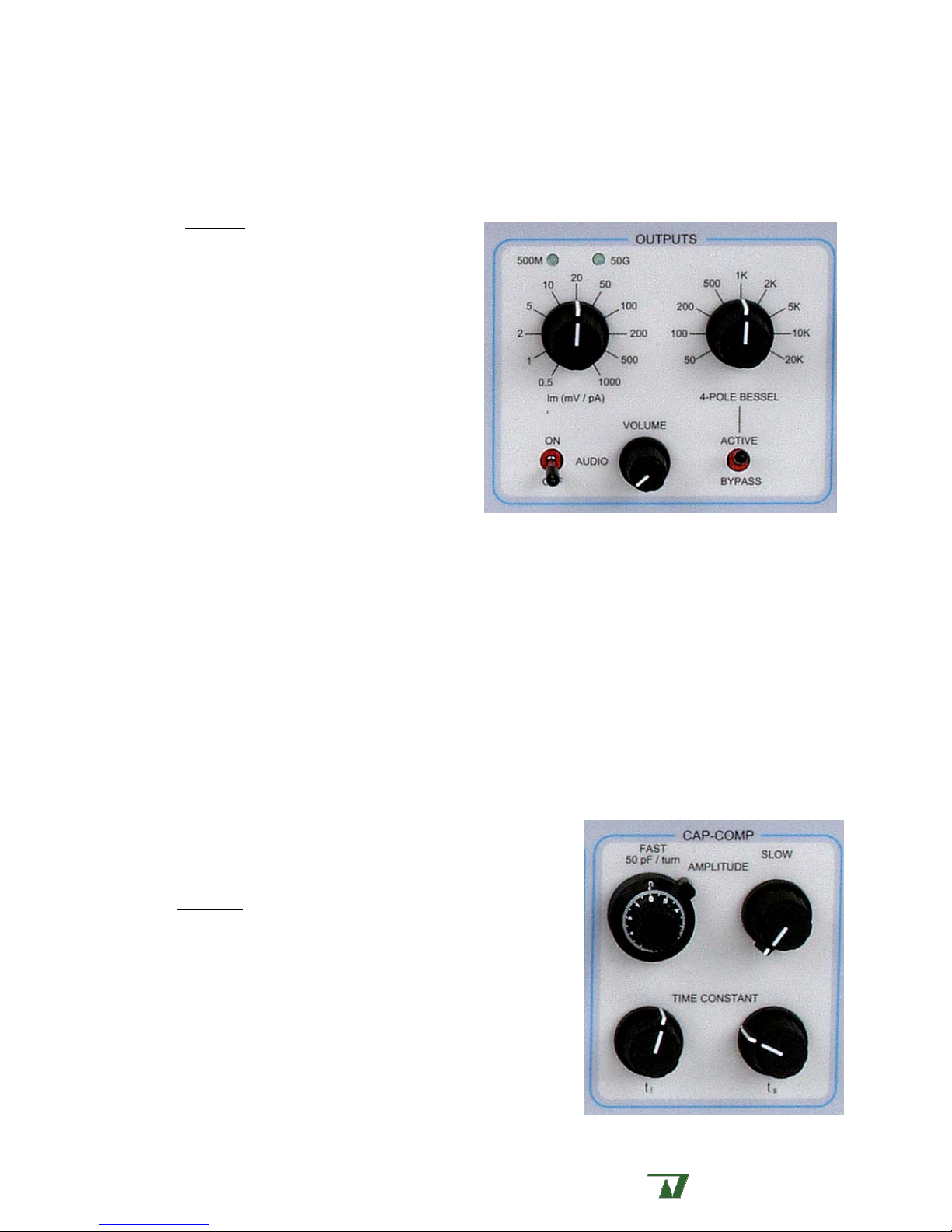
The OUTPUTS block contains controls for
selecting the I
filtering using the built-in 4-pole Bessel filter. This
block also contains the audio output controls.
Amplifier gain is selected via an 11 position
selector switch. Gain settings are from 0.5 to
1000 mV/pA in 1-2-5 steps. For transmission to
external devices, the selected gain setting appears
as a defined voltage at the
on the instrument rear panel.
Internal filtering of the Im signal is selected
via a 9 position selector switch. Filter settings are
from 50 Hz to 20 kHz in 1-2-5 steps. A
TOGGLE switch bypasses the 4-pole Bessel filter and presents the full bandwidth (75 kHz) of the
amplifier at the I
selected filter setting appears as a defined voltage at the
rear panel.
GAIN of the amplifier and signal
m
GAIN TELEGRAPH BNC
BYPASS
OUTPUT. Filtering is applied post-gain. For transmission to external devices, the
m
FILTER TELEGRAPH BNC on the instrument
The AUDIO section is comprised of an on/off toggle and volume control. Audio output is useful
during membrane formation to monitor the successful application of lipids. An open hole prior to
membrane formation produces a characteristic low frequency sound while the same aperture with
membrane produces a different characteristically higher frequency sound. The pitch of the signal is
keyed to the membrane capacitance and will increase as the capacitance increases allowing non-visual
monitoring of membrane ‘thinning’.
Capacitance compensation
The capacitance compensation circuit allows for cancellation
of large currents (capacity currents) generated when a step
potential is applied to the bilayer membrane.
CAP COMP block contains controls for the adjustment of
The
AMPLITUDE and TIME CONSTANT for both FAST (0-10 µs) and SLOW
(0-10 ms) components of the current. The adjustment is made
in pairs, that is, the
first adjusted to minimize the transient, followed by adjustment
of the
SLOW pair. Each pair is adjusted in turn as many times as
required to completely minimize the transient.
AMPLITUDE control for the FAST component is a ten turn
The
potentiometer with a counting dial and can be used to provide a
FAST pair (AMPLITUDE and TIME CONSTA NT) is
Warner
A Harvard Apparatus Company .
Instruments
Page 9
BC-535 Preliminary, Rev. 060126 9
reading of the capacitance in pF. The dial is calibrated to 50 pF/turn.
Power
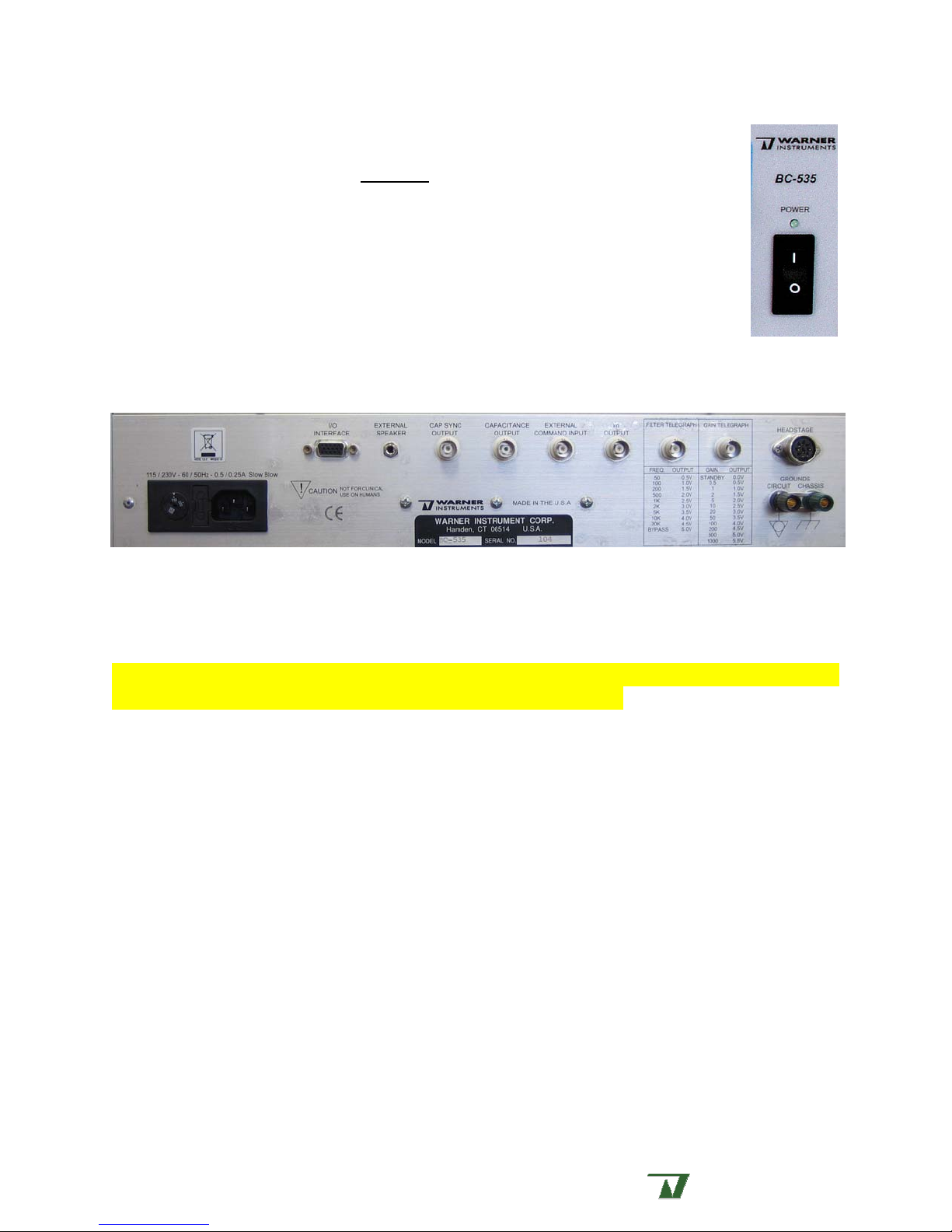
Immediately adjacent to the CAP COMP block is the master power switch for the
BC-535. An LED indicates power on status.
Rear panel
The instrument rear panel has BNC connectors for GAIN and FILTER TELEGRAPHS, I
OUTPUT, CAP SYNC, EXTERNAL RESET IN, and EXTERNAL COMMAND IN. A 9-pin DIN
connector (for the headstage), a 15 pin I/O
CHASSIS GROUND, and a SPEAKER OUTPUT are also located on the rear panel.
INTERFACE, binding posts for CIRCUIT and
M
The photo below shows the various attachment points on the instrument rear panel. Connections
are described right-to-left.
Headstage
The HEADSTAGE is housed in a small aluminum enclosure and connects to the amplifi er via a 1.8 meter
cable. A 9-pin DIN connector is provided for this attachment.
Note: When routing the headstage cable from your Faraday cage to the instrument, we recommend
intertwining the headstage and ground cables to minimize ground loops.
Circuit and chassis grounds
CIRCUIT and CHASSIS GROUND binding posts are provided at the rear of the amplifier to allow
modification of instrument grounding.
The CHASSIS GROUND binding post is internally connected to the green-wire ground of the power
plug. Therefore the instrument does not normally require a separate ground. However, it may becom e
necessary to independently ground the chassis of the
and not incorporated into a rack.
The CIRCUIT GROUND binding post allows external connection to the internal ground circuitry of
the amplifier. This post is used to provide a common circuit ground point for all active components
(Faraday cage and contents, SUNStir-3 assembly, temperature controller, etc.) withi n the bilayer rig,
thus preventing ground loops.
In general, the internal circuitry of the
connected to chassis ground. However, when necessary, the
to tie the circuit and chassis grounds to a common potential. This is the default configuration when the
instrument is shipped from the factory.
BC-535 when it is used as a freestanding devi ce
BC-535 maintains a virtual ground and is not normally not
CIRCUIT GROUND binding post can be used
Warner
A Harvard Apparatus Company .
Instruments
Page 10

BC-535 Preliminary, Rev. 060126 10
Note: We recommend separating the circuit and chassis grounds by di sconnecting the bridging bar
between the associated ground posts. Loosen the posts and slide the bridge to one side.
Gain Telegraph
The GAIN TELEGRAPH i s a stepped voltage output designed to communicate the instrument gain
setting to your acquisition software. DC voltages are stepped from 0.0 V to 5.5 V, in steps of 500 mV.
GAIN TELEGRAPH voltage outputs for the associated amplifier I
settings are selectable in the front panel
Gain (mV/pA) Gain Telegraph (V)
I
m
standby 0.0
0.5 0.5
1 1.0
2 1.5
5 2.0
10 2.5
20 3.0
50 3.5
100 4.0
200 4.5
500 5.0
1000 5.5
OUTPUTS block, see page 8)
GAIN are specified below. (Im GAIN
m
Filter Telegraph
The FILT ER TELEGRAPH is a stepped voltage output designed to communicate the instrument filter
cutoff frequency setting to your acquisition software. DC voltages are stepped from 0.5 V to 5.0 V, in
steps of 500 mV and are specified below. (
block, see page 8)
Filter Frequency (Hz) Filter Telegraph (V)
50 0.5
100 1.0
200 1.5
500 2.0
1k 2.5
2k 3.0
5k 3.5
10k 4.0
20k 4.5
bypass 5.0
FILTER settings are selectable in the front panel OUTPUTS
Warner
A Harvard Apparatus Company .
Instruments
Page 11

BC-535 Preliminary, Rev. 060126 11
Im output
The Im OUTPUT signal present on the instrument front panel is mirrored on this rear panel BNC.
Use of this output rather than the front panel BNC can unclutter your work environment.
External Command In
External COMMAND IN signals can be input via BNC connectors on either the instrument front
panel or the instrument rear panel. Input location is selectable by the front/rear
toggle switch located in the
HOLD control block on the instrument front panel. Use of the rear input
COMMAND INPUT
can unclutter your work environment.
Capacitance Output
The calculated membrane capacitance is output on this BNC when the instrument is in CAP TEST
mode. Switching the
METER selector switch to CAP TEST activates the CAP TEST circuit. This feature is
useful for recording the calculated membrane capacitance into a chart recorder or data acquisition
system. Capacitance output values are 1 mV/pF.
Cap Sync Out
This signal is used to synchronize an oscilloscope or other device with the BC-535 when using the
CAP TEST function. The SYNC OUT signal is keyed to the peak of the triangular wave for CAP TEST which
corresponds to the leading edge of the resulting square wave. The
square wave and is 100 µs in duration.
SYNC OUT signal is a standard TTL
External speaker
A standard ¼” RCA jack is provided for attachment to an external speaker for use in
environments where the ambient noise exceeds the volume capabilities of the internal speaker.
ADDITIONAL INFORMATION
Headstage connections
The HEADSTAGE is housed in a small aluminum enclosure and connects to the amplifier via a 1.8
meter cable. Electrode connections are made to two 1 mm mini-jacks marked
(reference). A third mini-jack (
GND; circuit ground) is located on the side of the headstage for
connecting to shields or grounding equipment.
The ground connection on the headstage merits specific discussion. The headstage case is
internally connected to the command potential (
INPUT electrode) of the headstage. As a result, the
headstage does not require a separate ground. However, the isolated grounding jack on the headstage
is provided as a means to ground a small Faraday cage through the headstage if the user desires.
Notes:
1. If the Faraday cage is grounded through the headstage (not recommended), then do not run
a separate ground connection from the Faraday cage to any other ground point.
2. Do not connect the ground on the headstage to either the input or ref electrode as this will
disable the amplifier.
INPUT and REF
Warner
A Harvard Apparatus Company .
Instruments
Page 12

BC-535 Preliminary, Rev. 060126 12
Model membrane
The BC-535 is shipped with a model membrane, the MC-1, which can be used to test the
performance of the amplifier. The
resistor. The precision of this resistor is ± 5%.
MC-1 connects to the two 1 mm mini-jacks on the headstage marked INPUT and REF. The
The
green grounding wire on the
MC-1 contains a 100 pF capacitor connected in parallel with a 1 GΩ
MC-1 is attached to the isolated grounding jack on the headstage.
Warner
A Harvard Apparatus Company .
Instruments
Page 13
BC-535 Preliminary, Rev. 060126 13
SETUP
For those with little experience in bilayer work, we suggest a review of Ion Channel
Reconstitution edited by C. Miller, Plenum Press, New York, 1986. In particular, Chapter 5, "How To
Set Up A Bilayer System", covers many important aspects of the subject. Several other pertinent
references are included in the appendix at the back of this manual.
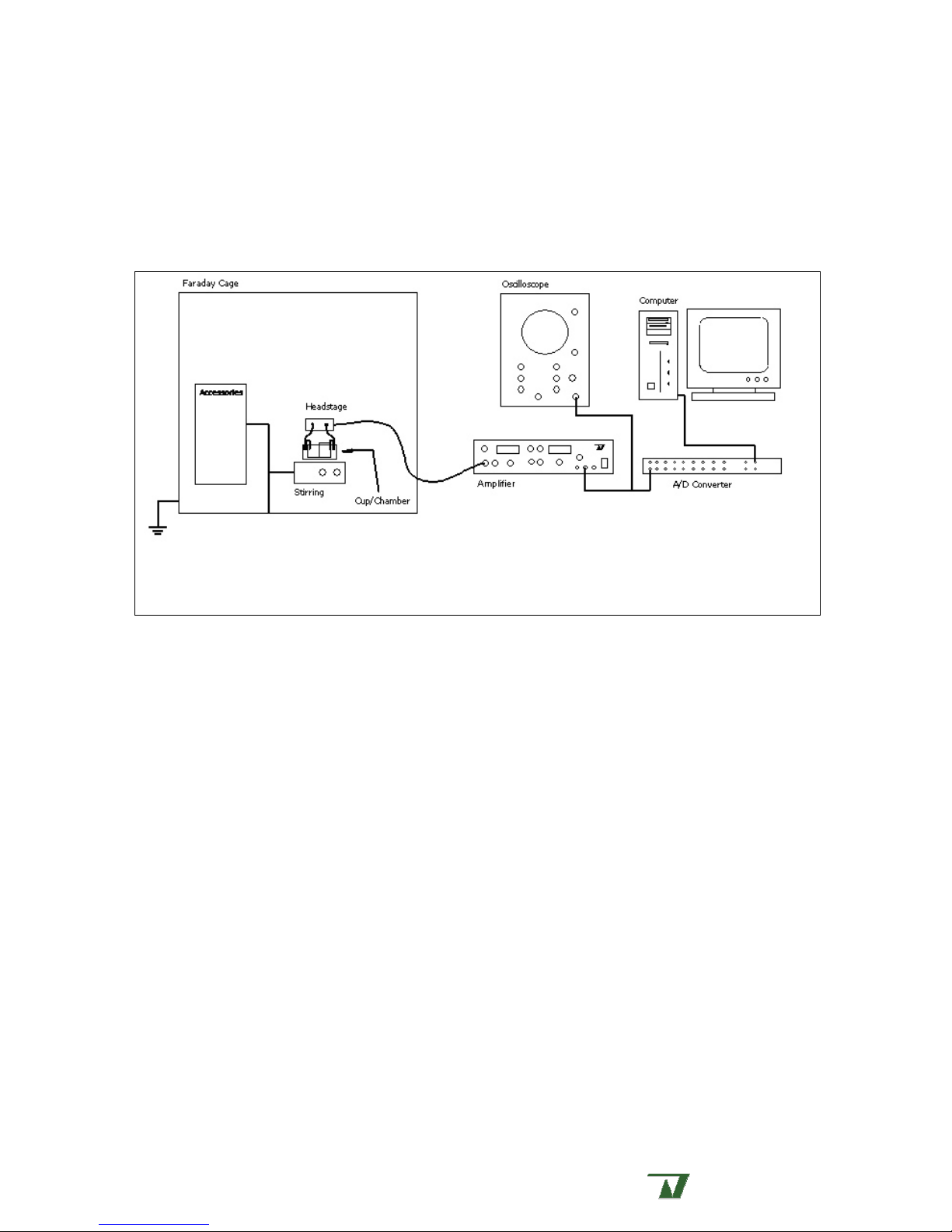
Figure 1. Schematic representation of a BLM setup.
Basic design
A planar lipid bilayer (BLM) workstation, used to record currents through actively gating, ion
conducting single channels, is a complex apparatus requiring several components working in concert.
These components include a means to support the lipid membrane, high gain amplification, shielding
of electromagnetic interference, shielding of mechanical vibration, mechanisms for stirring and
changing solutions, signal filtering, data acquisition analysis, and a means to archive acquired data.
A schematic representation of a basic BLM layout is shown in Figure 1. Warner Instruments
provides all components used in the assembly of a BLM workstation, including Faraday cages,
vibration isolation tables, a dedicated bilayer clamp amplifier, high quality signal filtering devices,
illumination and stirring mechanisms, cups and chambers, and perfusion apparatus.
The components listed above may be assembled in various ways to achieve a working system.
Regardless of the configuration used, care must be taken in the design of a BLM workstation to
minimize both mechanical and electrical noise sources since single channel currents are often only a
few pA in magnitude. In this section we describe the basic design of a BLM workstation.
Faraday cage
A Faraday cage is an enclosure designed to shield the sensi tive electronics in the h eadstage from
electromagnetic interference generated by noise sources in the vicinity of the apparatus. These
sources include exterior lighting, nearby instrumentation and electrical wiring. The cage can be
fabricated from any conducting material and is grounded. While the design of the
BC-535 facilitates
Warner
A Harvard Apparatus Company .
Instruments
Page 14

BC-535 Preliminary, Rev. 060126 14
grounding the Faraday cage through the headstage (see Headstage connections, page 11 ), we do not
recommend this procedure, but instead suggest that the cage be grounded through the amplifier
circuit ground.
Several Faraday cage designs are available. The most common commercial design is that of a
copper or aluminum wire mesh supported on an aluminum frame. This frame attaches to the
conducting top of a floor-standing vibration isolation table which completes the cage enclosure. Entry
is through large front panel doors. This design is most often used in conjunction with patch clamp
setups since the large enclosure can house a microscope as well as several other devices.
An option exclusively presented by Warner Instruments consists of a Faraday cage with an
enclosed vibration isolation table. This unique combination is specifically designed with the bilayer user
in mind. The assembly requires little lab space, rests comfortably on a sturdy work surface, and
actively isolates the tabletop from the cage enclosure. The cage is easily assembled and has several
design features simplifying bilayer work.
Regardless of the Faraday cage employed, the headstage and membrane support system (e.g.
cups and chambers) are contained within the cage which acts as the electromagnetic shield. Other
devices such as a perfusion system or stirring apparatus may also be housed within the cage, but
some investigators place these components on the outside (with proper grounding) to reduce their
noise contribution.
Vibration isolation
The isolation and damping of mechanical noise is critical to increasing the signal to noise ratio of
a BLM workstation. The significance of this becomes apparent when one considers that the acousti c
coupling of normal speech to the buffers on each side of the bilayer is large enough to present a
significant capacitance current artifact in the data.
Several approaches have been employed to eliminate large amplitude mechanical vibrations in an
experimental setup. These include specially designed vibration isolation tables or optical benches.
These floor standing benches employ a heavy table top resting on pneumatic supports. Alternatively,
investigators have placed heavy concrete slabs (commonly referred to as balance tables) or large steel
sheets on partially inflated inner tubes or tennis balls. We recommend the use of a high quality
commercial table since these devices provide more long term stability and more effectively damp
vibrational noise inputs.
Another, more subtle, source of noise in electrophysiological recording systems is associ ated with
vibration of the headstage. This movement can produce a rapidly fluctuating stray capacitance which
appears as increased noise in the amplifier output. This effect can be minimized by shock mounting
the headstage to its support. Since it is advantageous to keep the associated moment arm as small as
possible, the headstage should be directly mounted to its support rather than through a long
connecting rod. Warner Instruments has developed the
this purpose.
HST-1 headstage holder system expressly for
Membrane support
The general approach to the formation of a planar lipid bilayer membrane involves spanning lipids
across a small hole or aperture in a membrane support. A cocktail of l ipids, usually suspended in a
Warner
A Harvard Apparatus Company .
Instruments
Page 15

BC-535 Preliminary, Rev. 060126 15
solvent such as decane, is manually painted or drawn across the aperture. Excess l ipids drain away
from the aperture and under hydrophobic pressure the remaining lipids orient themselves into a
molecular bilayer.
Planar lipid bilayer membranes are routinely generated on a variety of supports i ncluding cups
made from polystyrene, polysulfone, Teflon, or Delrin. Teflon sheets, Pasteur pipette tips, or plastic
septa have also been used. These supports are either custom fabricated for the d esired application or
are purchased from commercial sources. Currently, the most commonly used system for supporting
artificial bilayer membranes is the cup/chamber design. Warner Instruments manufactures cups and
chambers in several combinations of material, cup volume and aperture size. These may be viewed in
our catalog or at our website under the model numbers
BCH-13, BCH-22 and BCH-P.
The geometry of the aperture is important to the stability of the supported membrane. If the hole
diameter is too large then the membrane formed will be electrically noisy and mechanically fragile. A
smaller hole diameter reduces electrical noise and is mechanically more robust, however, the
probability that a vesicle will fuse to the membrane is inversely proportional to the membrane size.
The simplest aperture geometry is that of a tubular channel drilled through the supporting septa.
This geometry has the advantage of being easy to manufacture and maintain. It is generally assumed
that the membrane formed is maintained at one end of the bore. This is the design employed by
Warner cups.
Another aperture geometry commonly used is that of a conical hole with the small end of the hole
supporting the bilayer membrane. This geometry, often employed on custom made cups, is generally
formed by melting a small bubble (or boss) in the cup wall from the i nside using a heated piece of
pointed metal, and then shaving the outside boss away with a razor until a hole of the desired
diameter is achieved.
Based on the above discussion, it is clear that the choice of hole size and geometry repr esents a
trade-off between membrane noise, fragility, and the probability of vesicle fusion. The best hole for a
particular application is usually determined empirically.
Amplification
A high-quality amplifier is an absolute requirement for recording single channel currents. The
amplifier must be capable of resolving currents as low as 1 pA with very little added noise. While
several manufacturers today produce amplifiers of high-quality, the greatest degree of variation
between instruments is in the feature set. Warner Instruments is the only manufacturer to produce a
dedicated bilayer clamp amplifier, and it’s performance and feature set have been optimized for
bilayer work.
Filtering
Filtering of the amplifier output is essential for resolving discrete channel fluctuations from the
large amplitude high frequency noise present in the signal. Properly applied filtering is important since
over-filtering of the data will obscure or modify channel gating events (a conditi on to be avoided!),
while an under-filtered signal will not clearly resolve single channel events . The BC-535 provides a
built-in 4-pole Bessel filter which can be used to select filtering from 50 Hz to 20 kHz, or can be
bypassed.
Warner
A Harvard Apparatus Company .
Instruments
Page 16

BC-535 Preliminary, Rev. 060126 16
Optionally, many researchers filter their data using an external device. These devices are
normally of the low-pass 8-pole Bessel design. While Butterworth filters have steeper frequency cutoff
characteristics, they are less commonly used since they tend to overshooting a rapidly varyi ng signal
thus introducing an artifact into the data. In general, it is better to slightly under-filter the data being
acquired in real-time since additional filtering can be performed later in the analysis software.
Warner Instruments provides a number of filtering devices which can be used in conjunction with
BC-535 to achieve a high degree of filter resolution. We recommend the use of a high quality
the
8-pole Bessel filter such as the
LPF-8.
Acquisition hardware and software
Since the analysis of single channel data is statistical in nature, a large number of channel events
is required to produce significant results. This condition naturally lends itself to the use of a computer.
However, since computers function digitally, the analog signal from the amplifier must first be
digitized by an analog to digital (A/D) converter prior to analysis. Many A/D converters are bundled
with software which emulates a chart recorder or oscilloscope to aid in data acquisition.
Since single channel gating kinetics can range from sub-ms open times to gating transitions
lasting several seconds or more, the desired characteristics of a high-quality A/D converter include
rapid response times, high signal resolution and low noise.
Data analysis
Once the data has been acquired and stored, it must be analyzed for its biophysical
characteristics. Since the volume of data collected is often exceedingly large, analysis is usually
performed by dedicated software programs. The single most popular program for this purpose is
pClamp (Molecular Devices, Sunnyvale, CA). However, several competing software packages are
available commercially or on the Internet. In addition, many investigators have written their own
programs to address their specific needs.
Data archival
The ability to easily archive and retrieve data is an important component of a BLM workstation.
During the course of an average experiment, a large volume of data is collected for later analysis.
Several devices are available for data storage. These devices include, but are not limited to: VC R tape
(requires a signal converter or pulse code modulator), DAT tape, portable or removable hard drives,
Zip or Jazz drives, CD-RW, or the newer DVD-RW technology.
An important advantage of most of these archival systems is that they allow selective access to
previously recorded data for subsequent analysis. The choice of the proper system will depen d upon
the needs of the researcher, the financial resources available, and the type of data acquired (fast or
slow channel kinetics resulting in large or small file sizes).
Stirring
Stirring of solutions in the recording chamber is important for the production of reproducible
results, especially following the addition of agonists or antagonists. Additionally, stirring is thought to
facilitate the fusion of vesicles to the bilayer membrane, presumably by vibrati ng the membrane or by
continuously introducing new vesicles to the bilayer. Ideally, the stirring process should produce
Warner
A Harvard Apparatus Company .
Instruments
Page 17

BC-535 Preliminary, Rev. 060126 17
sufficiently little mechanical noise such that one is able to make recordings while simultaneously
stirring.
Warner Instruments has developed a unique stirplate specifically designed for the planar lipid
bilayer. This stirplate, the
SPIN-2, provides separate rotating dipoles for each side (cis and trans) of
the cup/chamber and its noise-free operation allows data recording while stirring.
Perfusion
Exchange of solutions (termed perfusion) normally occurs following incorporation of a channel to
the bilayer membrane, when experimental conditions require an alteration in ionic conditions, or to
remove a previously added compound.
Under ideal circumstances a good perfusion system is capable of exchanging solutions in the
recording chamber without interrupting the recording process or rupturing the membrane. However,
most researchers do not attempt to make recordings while perfusing since this is likely to result in a
broken membrane.
Several techniques for solution exchange are available. These include gravity feed, pump driven
devices, or manually-applied pressure driven systems. In general, fresh solution is added to the
bottom of the recording chamber while the perfusate is removed from the top. Warner Instrument s
has developed the
with our Bilayer Workstation.
BPS-2, an easily assembled ‘traditional’ perfusion system, which integrates well
Oscilloscope
While many investigators use software emulated display devices coupled to their acquisition
hardware to view data during acquisition, others rely on dedicated instrumentati on for this purpose.
These dedicated instruments include chart recorders and oscilloscopes.
The primary advantage of an oscilloscope over a chart recorder is one of speed. A chart recorder,
however, produces a permanent record that is lacking in an oscilloscope. Software emulation can
model either of these hardware devices. Regardless of whether the investigator uses a chart recorder,
an oscilloscope, or a software emulated device, the data is previewed during acquisition and is stored
for subsequent analysis.
Warner
A Harvard Apparatus Company .
Instruments
Page 18

BC-535 Preliminary, Rev. 060126 18
INITIAL TEST
This section describes the basic setup for incorporating the amplifier and headstage into the BLM
workstation. Procedures for testing the performance of the BC-535 immediately follow.
Amplifier setup
The headstage connects to the amplifier via a 1.8 meter cable. It is a good idea to route the cable
through a short shield (anti-wave guide) prior to its entering the Faraday cage. The presence of the
shield will have no effect on the signal received by the amplifier but can help reduce the amount of
electromagnetic interference entering the Faraday cage through the opening.
Since movement of the headstage can appear as a fluctuating stray capacitance at the headstage
input, the headstage should be rigidly mounted to a fixed support. The heads tage is shipped mounted
to a platform that can be attached to various holders or micro-manipulators. In addition, the
headstage should be placed as close to the preparati on as possible to reduce noise due to increased
input capacitance.
Overview
The procedures described here are provided to verify the functionality of the BC-535. These
procedures should be performed when you first acquire the amplifier and can also be used re-assess
the performance of the amplifier at a later time.
To perform these tests you will need:
BC-535 Bilayer Clamp amplifier
•
• included headstage
• included model membrane
• Faraday cage
• an oscilloscope (storage scope if available)
• 2 BNC connector cables
Initial conditions
Verify that the amplifier is disconnected and the power switch is off.
Place the
connect the cage to the
cage, then make a ground connection from the cage enclosure to the coupled
GROUNDS
on the rear of the BC-535.
Connect the headstage to the amplifier via the input on the rear panel. Connect the provided
power cable from the amplifier to your line source. You are now ready to begin the functional check of
BC-535.
the
CAUTION: Connection of the BC-535 to the wrong line voltage could result in severe damage to
the instrument. Therefore, before connecting the amplifier to the power source, check the serial
number label on the rear of the amplifier for its voltage rating. Prior to turning on the BC-535 for the
first time, verify that the line voltage is correct for the instrument. If the instrument voltage rating is
incorrect for your area, contact our Service Department.
HEADSTAGE into the Faraday cage. If using a small (1 cu ft or less) Faraday cage, then
GROUNDING JACK (green plug) on the HEADSTAGE. If using a larger Faraday
CHASSIS/CIRCUIT
Warner
A Harvard Apparatus Company .
Instruments
Page 19

BC-535 Preliminary, Rev. 060126 19
Set all controls on the instrument to the values specified below.
Control block Control Setting
HOLD OPERATE TOGGLE
COMMANDS APPLIED TOGGLE
VOLTAGE UP/DOWN TOGGLES
OFFSET AUTOZERO
METER SELECTOR SWITCH
OUTPUTS GAIN SELECTOR
COMMAND INPUT FRONT/REAR
TOGGLE
COMMAND INPUT ATTENUATION
TOGGLE
FILTER SELECTOR
FILTER TOGGLE
AUDIO TOGGLE
CAP COMP ALL CONTROLS
standby
off
adjust until meter reads 0
off
x0.01
inactive
(
ACTIVE LED is off)
Σ
V
c
10 mV/pA
5 kHz
active
off
Set to zero
Set the oscilloscope to the following settings:
• Connect V
your oscilloscope.
• time base to 5 ms/div
Turn on both the
x10 OUTPUT to the input of
c
BC-535 and the oscilloscope.
• voltage base to 0.2 V/div
• auto trigger
• DC coupling on the input channel
Hold voltage test
• Connect the model membrane (MC-1) to the headstage inputs and the green wire from the
model membrane to the headstage grounding jack. Insure that the Faraday cage remains
grounded, either through the headstage grounding jack or to the amplifier circuit grounding
post.
• Switch the
• Switch the
• Activate the
position. The
• Adjust the
OFFSET block) until the meter in the METER block reads 0 mV.
STANDBY/OPERATE switch to operate.
SELECTOR SWITCH in the METER block to offset.
OFFSET CONTROLS in the OFFSET block by moving the UNLOCK toggle to the unlock
ACTIVE LED will light and the toggle switch will return to its original position.
MANUAL INPUT OFFSET control (the twiddle-knob under the LOW/HIGH LEDS in the
Warner
A Harvard Apparatus Company .
Instruments
Page 20

BC-535 Preliminary, Rev. 060126 20
• Deactivate the OFFSET CONTROLS by moving the UNLOCK toggle to the unlock position. The
ACTIVE LED will go off and the toggle will return to its original position. The offset reading on
METER in the METER block will not change.
the
• Adjust the position of the trace on the oscilloscope to a convenient reference line.
• Switch the
• Using the
SELECTOR SWITCH in the METER block to
VOLTAGE UP/DOWN TOGGLE switches in the HOLD block, adjust hold potential until
Σ
Vc.
the meter reads 20 mV.
• Switch the
COMMANDS APPLIED toggle in the HOLD bl ock to on. The COMMANDS APPLIED LED will
light.
• Notice that the displayed voltage on the oscilloscope moves from zero to 0.2 V (one division
upward).
• Notice that the
applied V
HOLD multiplied by 10 (e.g.: 20 mV x 10 = 0.2 V).
m
METER also shows 20 mV. This reading is correct since the V
X 10 OUTPUT is the
c
• Switch the amplifier to standby. Notice that the applied voltage appears at the headstage
input even when the amplifier is in standby mode or when the headstage has open inputs
(i.e. the oscilloscope trace doesn’t change when amp is in standby).
• Make similar adjustments to the hold control to assure yourself that the amplifier performs as
expected.
• Switch the
• Using the
COMMANDS APPLIED toggle in the HOLD block to off.
VOLTAGE UP/DOWN TOGGLE switches in the HOLD block, adjust hold potential until
the meter reads 0 mV.
• Place the amplifier into standby.
Input noise test without model membrane
• Remove the model membrane. Insure that the Faraday cage remains grounded, either
through the headstage grounding jack or to the amplifier grounding posts.
• Move the BNC connection from the V
and monitor the I
• Set the amplifier
• Verify that the
• Verify that the
• Switch the
OUTPUT with the oscilloscope.
m
GAIN to 100 mV/pA and the oscilloscope voltage base to 50 mV/div.
FILTER TOGGLE is active and switch the FILTER control to 1 kHz.
COMMANDS APPLIED toggle in the HOLD block is set to off.
STANDBY/OPERATE switch to operate. You should observe that the noise level
X 10 OUTPUT to the Im OUTPUT (in the OUTPUTS block)
m
decreases to no greater than 30 mV p-p. At a gain setting of 100 mV/pA this corresponds to a
maximum noise level of 0.043 pA RMS.
• Place the amplifier into standby.
Input noise test with model membrane
• Connect the model membrane (MC-1) to the headstage inputs and the green wire from the
model membrane to the headstage grounding jack. Insure that the Faraday cage remains
grounded, either through the headstage grounding jack or to the amplifier grounding posts.
• Set the I
• Set the oscilloscope voltage base to 10 mV/div.
• Verify that the filter is set to 1 kHz.
• Verify that the
GAIN on the amplifier to 5 mV/pA.
m
COMMANDS APPLIED toggle in the HOLD block is set to off.
Warner
A Harvard Apparatus Company .
Instruments
Page 21

BC-535 Preliminary, Rev. 060126 21
• Switch the STANDBY/OPERATE switch to operate.
• You should observe a noise level of no greater than 6 mV p-p, equivalent to 0.171 pA RMS at
this gain setting.
• Place the amplifier into standby.
Test instrument Im output
• Switch the SELECTOR SWITCH in the METER block to Im.
• Set the amplifier
• Set the oscilloscope voltage base to 0.5 V/div.
• Using the
40 mV.
• Set the
COMMANDS APPLIED toggle to on. The COMMANDS APPLIED LED will light.
• Set that the
• Verify that the
• Verify that the oscilloscope reads 0.8 V (or 1.6 div), equivalent to 40 pA at this gain setting.
(40 pA x 20 mV/pA = 800 mV on oscilloscope)
• Adjust the gain, oscilloscope, and holding potential settings to verify that the instrument is
working properly.
• Set the
COMMANDS APPLIED toggle to off.
• Using the
0 mV.
• Place the amplifier into standby.
GAIN to 20 mV/pA
UP/DOWN toggle switches in the HOLD block, adjust the V
STANDBY/OPERATE switch to operate.
METER reads 40 pA.
UP/DOWN toggle switches in the HOLD block, adjust the V
HOLD until it reads
m
HOLD until it reads
m
Cap test
• With the model membrane still connected, set the oscilloscope voltage base to 50 mV/div.
• Set the I
GAIN on the amplifier to 1 mV/pA.
m
• Place the amplifier into operate.
• Activate
• The I
CAP TEST mode by setting the METER SELECTOR SWITCH to cap test.
OUTPUT will now be a 100 Hz square wav e with p-p amplitude of approximately 100
m
mV. This corresponds to a 100 pF membrane at this gain setting.
• Verify that the meter reports the model membrane capacitance of 100 pF.
• Place the amplifier into standby.
Autozero
• Set the oscilloscope voltage base to 100 mV/div.
• Set the instrument
• Switch the
STANDBY/OPERATE switch to operate.
• Activate the
ACTIVE LED will light and the TOGGLE will return to its original position.
• Switch the
METER section). If not, adjust to 0 mV using the MANUAL OFFSET CONTROL.
METER SELECTOR to offset and verify that the offset potential is 0 mV (viewed in the
• Adjust the oscilloscope signal to a convenient reference point.
• Using the
MANUAL OFFSET CONTROL, increase the offset potential to 10 mV.
(Note: Fine adjustment of the offset setting can be achieved by pushing in the OFFSET
CONTROL while turning.)
GAIN to 10 mV/pA.
OFFSET CONTROLS by moving the OFFSET TOGGLE into the unlock position. The
Warner
A Harvard Apparatus Company .
Instruments
Page 22

BC-535 Preliminary, Rev. 060126 22
• Verify that the signal on the oscilloscope moved 1 div upwards. This corresponds to a 10 pA
offset at this gain setting.
• Depress the
• The
ACTIVE LED will flash, indicating operation of the AUTOZERO function.
• Verify that the I
• Verify that the
• Switch the
AUTO-ZERO pushbutton.
OUTPUT signal on the oscilloscope returns to baseline.
m
OFFSET reading on the METER returns to 0 mV and that the ACTIVE LED is off.
STANDBY/OPERATE switch to standby.
Capacity compensation
Function of the capacity compensation circuit can be checked by attaching an externally
generated square wave to the
membrane is achieved by switching the
• Apply a square wave to the model membrane and observe the resulting signal on the
oscilloscope. You will see a large transient on the leading edge of both the upward and
downward excursions of the signal. This transient (or spike) represent the large amplitude
current associated with the charging of the membrane capacitance.
• Adjusting the
CAP COMP FAST AMPLITUDE control clockwise will reduce the spike. Slowly rotate
this the control until a minimum is observed (this should be at a reading of approximately 2.0
on the amplitude dial, indicating a 100 pF capacitor).
• If necessary, adjust the
to further minimize the amplitude of the spike.
• Additional adjustment of the
transient.
• Continue adjusting both controls until the overshoot is removed.
• Set the
OPERATE/STANDBY switch to standby and disconnect the model membrane.
FRONT COMMAND IN BNC. Application of the signal to the model
COMMAND INPUT TOGGLE to front.
FAST TIME CONSTANT control (directly below the FAST AMPLITUDE control)
SLOW CONTROLS may be necessary to completely minimize the
This completes the instrument check out.
Warner
A Harvard Apparatus Company .
Instruments
Page 23

BC-535 Preliminary, Rev. 060126 23
OPERATION
The general procedure is to first set up the bilayer chamber, add solutions, and make electrical
contact. This is followed by adjusting the input offset and forming the bilayer membrane. The strategy
for incorporating channel containing membrane vesicles to the bilayer membrane will depend on the
system under study, but will normally proceed by adding vesicles or purifi ed protein to on e side of the
membrane under the appropriate ionic and/or osmotic conditions. Once a channel has been
successfully incorporated into the bilayer the solutions are perfused and initial experimental conditions
established. At this point recording of data proceeds.
Setup of the bilayer chamber
Bilayer membranes are formed across an aperture in a septum which separates two chambers.
The most common configuration is that of a cup (which supports the aperture) placed inside a holder.
The interior of the cup represents one chamber while the interior of the holder is the other chamber.
The cup wall is the septum. Electrical connections are made via agar salt bridges into each chamber.
The whole assembly must be shielded from electrical and vibrational interference to obtain low noise
recording of bilayer currents.
The aperture is prepared to accept lipids prior to membrane formation. This is achieved by
‘coating’ the hole with the lipid cocktail before adding solutions to the cup or chamber. Several
techniques are employed to coat the hole prior to membrane formation. While the choice of techni que
will depend on your application, the materials at hand, and your ingenuity and training, once the hole
has been coated, the cup is inserted into the chamber and both the cup and chamber filled with the
appropriate solutions. Two methods are presented below.
One method to coat the hole uses a small (1-2 mm) ball formed on the end of a glass rod or
Pasteur pipette with a Bunsen burner. The rod is dipped into the lipid mixture and a coating of lipids is
applied to the outside rim of the hole. An advantage of this technique is that it is relatively easy to
keep the glass rod, and hence the resulting membrane, free from contamination.
An alternative method is to insert several lipid-covered hairs from a Red Sable paintbrush through
the aperture. The brush is then revolved in a small circle until the hole is uniformly coated with lipid.
(Use a size 00 or 000 Red Sable artists dotting brush which has been trimmed to pr esent 3-5 hairs of
the same length. The brush is cleaned and dipped into the lipid cocktail before coating the hole.) As
suggested above, a disadvantage to this technique is that the brush can easil y become contaminated
over time or through misuse.
The headstage leads should not be directly connecte d to the bathin g solutions. Instead, leads ar e
routed to wells containing a salt solution which are in turn connected to the solution baths via agar
salt bridges. The salt bridge wells should ideally contain the same solution used in the formation of the
salt bridge, usually 1 M KCl. In addition, these wells should be adjacent to the baths so t hat the agar
bridges used to complete the circuit from well to bath are as short as possible. The suppli ed sliver-wire
electrodes require chloride-plating prior to their first use and insertion into the salt bridge wells. (See
Chloriding electrodes, Appendix.)
Warner
A Harvard Apparatus Company .
Instruments
Page 24

BC-535 Preliminary, Rev. 060126 24
Input offset
Prior to forming a bilayer membrane, the resistance of the aperture is exceedingly low, as small
as 1 kΩ. Consequently, an input voltage as small as 1 mV can i nduce a large currents ex ceeding 1 nA
to flow. These currents are much larger than the pA currents typical in single channel recording and
can overload the headstage.
Alternatively, a series resistance within the electrical pathway can introduce a bi as in the voltage
applied to the membrane resulting in a systematic offset in the data acquired. This offset will appear
as a junction potential.
It is therefore important to adjust the instrument input offset potential to compensate for these
conditions.
Input offset adjustment
The INPUT OFFSET control provides up to ±120 mV DC at the headstage to compensate for input
errors and solution junction potentials. The
adjustment of input offsets. Manual adjustment of the offset to zero can also be achieved using the
associated rotary control and is aided by the input overload LED’s marked high and low.
BC-535 has an AUTOZERO circuit which greatly simplifies
In any case,
If using the
AUTOZERO button. The amplifier will cycle through the setti ng, find the offset potential, and disarm the
AUTOZERO circuit. The results of the calculation (the applied offset voltage) will be presented to the
METER when the SELECTOR SWITCH is in the offset position.
junction corrections are performed in the absence of a membrane.
AUTOZERO circuit (recommended), then simply activate the circuit and press the
If using the manual approach, the control should be advanced slowly since a small change in
rotation will result in a large change in the current through the open aperture. When both LED’s are
off, the offset voltage will be near zero and the I
OUTPUT BNC. In general, it will be extremely difficult to set the Im current precisely to zero. It is
the I
m
current can be accurately read on the METER or from
m
sufficient to adjust the input offset until both the high and low LED indicators are both unlit.
At this point the
OFFSET METER reading will indicate the input to bath ground potential difference.
If this potential difference is large (greater than 10 mV for normal Ringer solution), then it is advisable
to clean and re-chloride the silver wire electrodes (see Chloriding electrodes, Appendix) and check the
agar bridges for deterioration or bubble formation. The potential difference reading sh ould be noted
prior to forming the bilayer membrane and rechecked at the end of the recor ding ses si on to det ermi ne
stability of the electrodes.
Note: Do not make adjustments to the INPUT OFFSET control once a membrane has been formed as
this will introduce a bias into your data.
Bilayer formation
Current through the open aperture will be quite high until lipid covers it. Therefore, by monitoring
in the presence of a small applied voltage, you can easily determine when the aperture is covered.
I
m
BC-535 has an integral audio amplifier to aid in monitoring membrane formation. In general, there
The
will be a dramatic drop in current as soon as lipid has filled the aperture and the audio signal will
change accordingly.
Warner
A Harvard Apparatus Company .
Instruments
Page 25

BC-535 Preliminary, Rev. 060126 25
To observe the formation of a membrane, set the HOLD TOGGLE (in the HOLD block) to the off
position, place the
SWITCH to cap test. Prior to membrane formation, and if the aperture is not occluded (with a bubble,
for example), the
OPERATE/STANDBY switch in the operate position, and turn the METER SELECTOR
METER will report 0 pF. In addition, the triangular wave generated by CAP TEST will
induce a trans-aperture current which exceeds the operational range of the amplifier input. This
results in the appearance of a full scale (10 V p-p) pseudo-square wave at the I
OUTPUT.
m
During membrane formation, the initial covering of the aperture by lipid dramatically decreases
the amplitude this square wave allowing you to observe the formation of the bilayer on an
oscilloscope. Additionally, the audio signal will change character and the
METER will begin to report an
increasing capacitance. As the bilayer continues to form you will observe a time-dependent increase in
the amplitude of the square wave on the oscilloscope representing an increase in membrane
capacitance.
In all cases, the capacitance increase is proportional to the area of the forming membrane and so
allows you to observe both the size and stability of the bilayer formed. (For additional discussion see
Membrane capacitance calculations, Appendix.)
If you are using the brush technique, then the bilayer membrane is initially formed by painting
lipids across the hole. This is achieved by dipping a clean brush i n the lipid cocktail and drawing a thi n
lipid film across the open aperture (reminiscent of making bubbles when you were a kid).
Alternatively, the membrane can be formed by momentarily occluding the hole with the end of the
lipid-coated glass rod. In either case, the lipids will initially occlude the hole in a thick layer. After a
short time (several seconds to a few minutes), excess lipids will drain away from the hole until a
bilayer is formed. The area of the forming membrane can be monitored on an oscilloscope or on the
meter. In general, several attempts of the above procedure may be necessary before a stable
membrane is formed.
Once the membrane has formed and appears stable,
CAP TEST should be turned off and the leak
conductance of the membrane checked. A good membrane will have a conductance of less than 10 pS
(i.e., 1pA/100mV).
Commands
Once a stable membrane is formed, the appropriate ionic and/or osmotic conditions are
established and channel bearing vesicles are added. The system is monitored in the presence of a
transmembrane holding potential for a vesicle ‘fusion event’. Once a channel has incorporated into the
bilayer membrane the solutions are quickly perfused to prevent further vesicle fusions and the
appropriate experimental conditions established.
Command voltages to the bilayer membrane are effected by the V
applied signal (
CMD IN) or by a combination of the two. V
polarity up to 400 mV. External signals at
Therefore, a 10 V DC signal at
CMD IN results in an applied voltage at the headstage of 1000, 10 0, or
CMD IN are attenuated by x0.1, x0.01, or x0.001.
HOLD provides a DC potential of either
m
10 mV, respectively, for attenuation settings of x0.1, x0.01, or x0.001.
HOLD control, by an externally
m
Warner
A Harvard Apparatus Company .
Instruments
Page 26

BC-535 Preliminary, Rev. 060126 26
APPENDIX
Theoretical considerations
Shielding
Proper shielding of all cabling and recording apparatus are important in maintaining a large
signal-to-noise ratio. The necessity of a high quality Faraday cage to protect the headstage from
stray input signals cannot be over emphasized. If the noise levels are still unacceptably high after
shielding, it may be possible to further reduce noise by wrapping all wiring between the Faraday
cage and amplifier in aluminum foil and grounding the foil cover. However, under normal
circumstances this should not be necessary. If the user chooses to wrap wiring in foil, care should
be taken to induce stray capacitance due to movement of the aluminum foil shield.
Grounding
Since a large signal-to-noise ratio is important in single channel recording, the effort to
eliminate ground loops in the circuit wiring gains significance. If your Faraday cage encloses a
number of devices (e.g., microscope, stirrers, stepper motors, etc.), then the most common
procedure is to create a central grounding location within the cage to which all instrumentation is
attached. This is most readily achieved by the formation of a "star ground” and is diagrammed in
the upper figure on the next page (central node grounding scheme). Mount a solid brass bar with
a number of attachment points to the inside of the Faraday cage and connect the cage and
grounds of all devices within the cage to this bar. The bar is then connected via a 14-16 gau ge
braided copper wire to an external central ground point which acts as the absolute reference for
all devices. A bar of this type is provided in Faraday cages supplied by Warner.
Note: If the Faraday cage is grounded to the star ground, then do not ground the cage to the
headstage.
Alternatively, if you use a small Faraday cage which does not contain numerous devices,
then you can greatly simplify the circuit wiring by connecting the Faraday cage directly to the
headstage ground jack. This design is also diagrammed on the next page (common mode
grounding scheme). The major differences between this scheme and the one descri bed above is
1) the Faraday cage is grounded through the amplifier headstage and 2) the Faraday cage is not
connected to the external ground.
Note: Do not connect the Faraday cage to any other ground point.
The choice of which configuration to use depends on the number of components available
and the response of your system to noise inputs. In general, it is better to use the central node
grounding scheme since any attached devices will tend to generate large induced currents in the
ground plane which can overwhelm the headstage. Nevertheless, if your setup is very simple,
then grounding the Faraday cage through the headstage can provide a simpler circuit with lower
noise.
For either configuration, the ground for all external devices should be attached to a single
external ground point. The
CIRCUIT GROUND and one for CHASSIS GROUND. The instrument is shipped with these two grounds
BC-535 has two grounding posts on the rear of the instrument, one for
Warner
A Harvard Apparatus Company .
Instruments
Page 27
BC-535 Preliminary, Rev. 060126 27
connected together, or bridged. We recommend severing this connection and only using the
CIRCUIT GROUND.
The schemes shown below and described above indicate connection of the
GROUND
configurations with the
to an external ground point. However, it is often advantageous to try different ground
BC-535 to determine which works best in your environment.
BC-535 CHASSIS
Note: We do not recommend connecting the BC-535 CIRCUIT GROUND (directly or indirectly) to the
oscilloscope chassis ground. Doing so will create a ground loop and increase noise levels wi thin
the data. This condition can be avoided by disconnecting the oscilloscope chassis ground from the
common ground point when connecting the BC-535 CIRCUIT GROUND to the external ground.
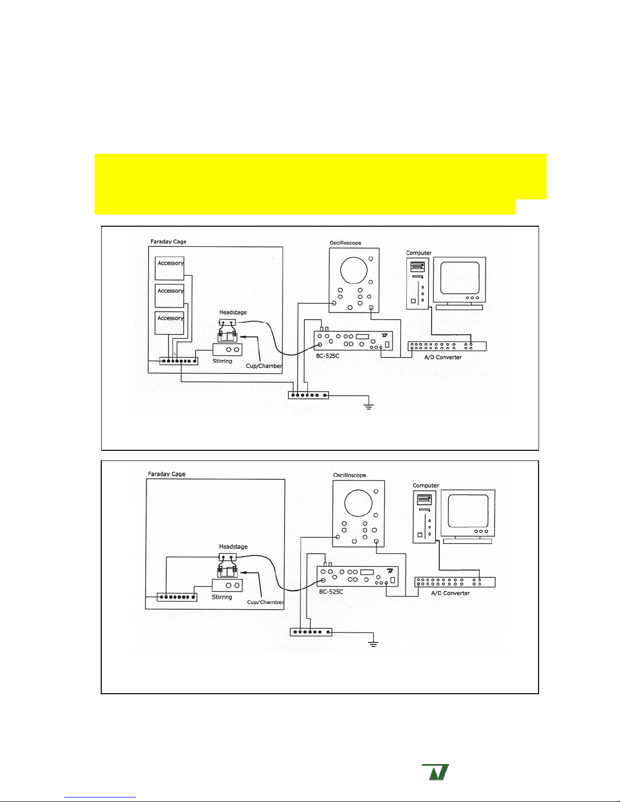
Figure 2a. Central node grounding scheme. Note the grounding block within the Faraday cage is
connected to the external star ground point and the headstage is not externally grounded.
Figure 2b. Common mode grounding scheme. Note the grounding block within the Faraday cage is
directly connected to the headstage. This mode only works for small cages containing few devices due
to the ground currents involved.
Warner
A Harvard Apparatus Company .
Instruments
Page 28

BC-535 Preliminary, Rev. 060126 28
=
=
Membrane capacitance calculations
It is possible to theoretically derive an equation to determine the size of the bilayer formed across
the aperture. While this equation will probably not yield an exact result (most likely due to variation in
the dielectric constant of your lipid mixture), it will give a reasonably approximate result.
Recall that we examine the formation of the bilayer by applying a triangular wave to the
membrane and observing a square wave at the I
capacitor returns the derivative of the applied voltage, as shown in the equations on the next page.
However, under normal circumstances you will most likely dispense with a calculation and visually
determine if the membrane size is appropriate by examining the amplitude of the square wave on the
oscilloscope.
From physics, we know that the equation describing the capacitance of a parallel plate capacitor
in the MKS system of units is
C
=
output. The reason we see a square wave is that a
m
A
(1)
ε
d
where C is the capacitance (in Farads), ε is the dielectric constant of the material between the plates,
A is the area of the plates and d is the plate separa tion (both in meters). Likewise, we know that that
the steady-state charge on a capacitor can be expressed as
CVq
(2)
where q is the charge on one capacitor plate (in Coulombs) and V is the potential between the plates
(in Volts). Equation (2) can be dynamically expressed by taking the time derivative of the charge, thus
dV
(3)
Ci =
dt
where the current
i =
dq
is defined as the time rate of change of the charge. Substituting equation
dt
(1) into equation (3) yields the general equation,
dV
A
i
ε
=
Recall that a bilayer membrane is electronically represented as a capacitor, and that we monitor
the forming bilayer through the application a triangular wave. Since a triangular wave, by definition,
has a constant rate of change of applied voltage,
dt
d
. (4)
dV
is constant. Likewise, since ε is an intrinsic
dt
property of the lipid mixture, it is also constant.
Now consider the forming bilayer membrane. Once a sufficient quantity of lipids have drained
away from the aperture, the remaining lipids begin to form a bilayer. Si nce the distance, d, separating
both sides of the membrane (the plates of our hypothetical capacitor) is fixed by the length of the lipid
tails, this term will also become constant. Therefore, the only remaining variable on the right side of
equation (4) is the area, A, of the forming bilayer. Thus we can express our equation as
(5)
kAi
Warner
A Harvard Apparatus Company .
Instruments
Page 29

BC-535 Preliminary, Rev. 060126 29
where i is the current appearing at th e Im output, k is a constant of proportionality, and A is the area
of the forming membrane. It should be apparent from the preceding discussion that the m agnitude of
the current, and hence the amplitude of the resulting square wave, is linearly proportional to the area
of the bilayer membrane.
Since the amplifier output is scaled to 1 mV/pF when the
BC-535 is in CAP TEST mode, application
of the preceding discussion to the amplifier indicates that the measured capaci tance of a membrane is
simply the amplitude of the square wave (expressed in mV) divided by the instrument gain. For
example, a 100 pF membrane would yield a 1000 mV square wav e (p-p) when the amplifier gain is set
to 10 mV/pA.
Suggested References
1. Ion Channel Reconstitution edited by C. Miller, Plenum Press, New York (1986). In particular,
chapter 5, "How to set up a bilayer system" covers many important aspects on the subject.
2. Single-Channel Recording edited by B. Sackman and E. Neher, Plenum Press, New York (1985).
3. Reconstituting channels into planar membranes: a conceptual framework and methods for fusing
vesicles to planar bilayer phospholipid membranes. F.S. Cohen and W.D. Niles, Methods in
Enzymology, 220:50-68 (1993)
4. Planar bilayer recording of ryanodine receptors of sarcoplasmic reticulum. R. Coronado, S.
Kawano, C.J. Lee, C. Valdivia, and H.H. Valdivia, Methods in Enzymology, 207:699-707 (1992)
Warner
A Harvard Apparatus Company .
Instruments
Page 30

BC-535 Preliminary, Rev. 060126 30
Specifications
Noise:
Measured with 8 pole Bessel filter at specified cutoff frequency
Frequency range Open input 100 pF at input
DC to 1 kHz 0.060 pA RMS 0.82 pA RMS
DC to 100 Hz 0.009 pA RMS 0.28 pA RMS
Bandwidth:
Input commands:
75 kHz
HOLD:
COMMAND IN:
Digital; 1 or 10 mV steps to ± 400 mV maximum
Front and rear external input, 10 V/V (applied voltage is attenuated
by 10/100/1000 at the command electrode)
Junction zero:
AutoZero or manual adjust. Offset lockout feature. Cycle time 1.5 s. Correction to ± 120
mV
Audio:
Capacitance test:
VCO with off switch and volume control. Internal speaker, and external speaker output.
Triangle wave applied to command electrode. Derived membrane capaci tance displayed
on meter up to 1000 pF. Calibrated (1 mV/pF) square wave available at I
m
Sync (rear panel) synchronized with input triangle wave.
Gain:
Filter:
Membrane current gain selectable from 0.5 to 1000 mV/pA in 1-2-5 steps.
4-pole Bessel, selectable from 0.5 to 200 kHz in 1-2-5 steps, or bypassed for full amplifier
bandwidth.
Capacity
compensation:
FAST (0-10 µs) and SLOW (0-10 ms) with adjustment of amplitude and time constant for
each range. Maximum compensation 500 pF.
output. Cap
Headstage:
Low current mode
High current mode
I/O:
Switching
50 GΩ feedback, 100 pA maximum current
500 MΩ feedback, 2 nA maximum current
Front panel:
Command Input: BNC input up to 10 V. Attenuated by 10, 100, or 1000.
I
output: Membrane current scaled by amplifier gain setting.
m
V
× 10 output: Applied command voltage × 10
c
Rear panel:
I
output: Membrane current scaled by amplifier gain setting.
m
Cap Sync: TTL compatible
Capacitance
Reports calculated membrane capacitance scaled to 1 mV/pF
output:
Command Input: BNC input up to 10 V. Attenuated by 10, 100, or 1000.
Gain telegraph: Stepped DC voltage 0.5 to 5.5 V in 0.5 V steps for gain
settings of 0.5 to 1000 mV/pA. Telegraph value of 0 V for
standby mode.
Filter telegraph: Stepped DC voltage 0.5 to 4.5 V in 0.5 V steps for filter
settings of 0.05 to 20 kHz. Telegraph value of 5.0 V for full
bandwidth (bypass) mode
External speaker: Standard RCA jack
Warner
A Harvard Apparatus Company .
Instruments
Page 31

BC-535 Preliminary, Rev. 060126 31
Specifications (continued)
Digital meter:
Power:
3.5 digit LED
Junction offset:
± 1999 mV full scale
± 120 mV full scale
Cap Test: 0 to 1999 pF
:
V
c
:
I
m
± 1999 mV full scale
± 1999 pA full scale
100-125 or 220-240 VAC, 50/60 Hz
Dimensions:
Case :
Headstage :
H × W × D
9 × 42 × 25 cm; (3.5 × 16.5 × 10 in)
2.3 × 2.8 × 5.8 cm (0.9 × 1.1 × 2.25 in)
1.8 m connecting cable
Operating
Conditions:
Equipment is intended to be operated
in a controlled laboratory
environment.
Temperature: 0-40 °C
Altitude: sea level to 2000 m
Relative humidity: 0-95%
Warner
A Harvard Apparatus Company .
Instruments
Page 32

BC-535 Preliminary, Rev. 060126 32
Chloriding electrodes
Silver-silver chloride electrodes act as signal transducers by converting i onic currents in solution
to an electric current within a wire. This is achieved by utilizing a reversible oxidation/reduction
-
reaction between the electrode and Cl
ions in solution. The chemical reaction is:
-
Cl
+ Ag ⇔ AgCl + e
-
The potential developed by one electrode is proportional to the standard el ectrochemi cal potenti al
for Ag/AgCl plus the Cl- concentration at the solution/electrode interface. Since this potential is
-
dependent on [Cl
], a voltage bias will be introduced by changing the solution Cl- concentration.
Therefore, we recommend that Ag/AgCl electrodes be connected to the bath through agar salt bri dges
-
to maintain a constant Cl
agar bridge will prevent Ag
The
BC-535 is shipped with two silver wires which must be chlorided prior to use. Over time, the
concentration near the electrode. In addition, the isolation provided by the
+
ions from contaminating the baths.
AgCl coating on the wires will deteriorate. This will be most apparent as a gradual increase in the
value of the junction potential seen at the beginning of each experiment. In addi tion, the electrodes
may lose their purple-brown color. Once it has been determined that the electrodes require cleaning,
the oxide should be removed and re-applied.
Techniques for chloriding silver wires
Before using Ag+ wire as a current or voltage electrode, it must first be chlorided. New
(previously unused) wire should be cleaned with ETOH before chloriding. Previously chlorided wire
should be cleaned before re-chloriding.
Two methods for chloriding most commonly used are the plating techniques described below.
These are soaking in household bleach or electroplating using a voltage source. As with a new wire,
clean the wire with ETOH before proceeding to remove finger oils.
A) Soaking in bleach - This technique places a very useable, but relatively thin coating on the
wire. Simply immerse the clean wire in full strength common household bleach (Clorox) for 515 minutes or until a purple-gray color is observed. Rinse and use.
B) Electroplating – While this technique requires more effort, it places a thicker and more
uniform coating on the silver wire. Electroplating a silver wire with chloride is achieved by
making the wire positive with respect to a solution containing NaCl (0.9%) or KCl (3M) and
2
passing a current through the electrode at a rate of ~1 mA/cm
of surface area for 10-15
seconds or until adequately plated. A 1 cm length of 1 mm diameter wire will require
approximately 0.3 mA. The color of a well plated wire will also be purple-gray. Periodic
reversal of the polarity while plating the electrode tends to yield a more stable electrode.
When electroplating a previously plated wire, you may find that it does not plate evenly.
Complete removal of the residual silver chloride is often necessary to effect a uniform coat.
Before making the wire positive to the chloriding solution, reverse the polarity for 5-10
seconds to remove any remaining chloride that might be left in pits on the wire. Then proceed
as described above.
Warner
A Harvard Apparatus Company .
Instruments
Page 33

BC-535 Preliminary, Rev. 060126 33
Accessories and replacement parts
Description Model No. Order No.
Classic bilayer chamber, 1 ml working volume
Classic bilayer cups, 1 ml working volume.
Available in various materials and aperture sizes.
150 um aperture size shown.
Classic bilayer chamber, 3 ml working volume
Classic bilayer cups, 3 ml working volume.
Available in various materials and aperture sizes.
150 um aperture size shown.
Perfusion bilayer chamber, 1 ml working volume
Perfusion bilayer cups, 1 ml working volume.
Available in various materials and aperture sizes.
150 um aperture size shown.
A dynamically variable single channel simulator. 100 pF
capacitance.
A non-variable version of the CM-3. 100 pF capacitance.
Bare silver wire, 1 mm pins with attached, 10 cm, 2 ea
BCH-13A 64-0400
CD13A-150
CP13A-150
CF13A-150
64-0410
64-0404
64-0416
BCH-22A 64-0401
CD22A-150
CP22A-150
CF22A-150
64-0413
64-0407
64-0419
BCH-P 64-0423
CD-P150
CP-P150
64-0427
64-0424
CM-3/100 64-0027
CM-1/100 64-0025
WA10-5 64-1327
Warranty
The model BC-535 is covered by our Warranty to be free from defects in materials and
workmanship for a period of three years from the date of shipment. If a failure occurs within this
period, we will either repair or replace the faulty component(s). This warranty does not cover
instrument failure or damage caused by physical abuse or electrical stress (inputs exceeding specified
limits). In the event that instrument repairs are necessary, shipping charges to the fact ory are the
customer's responsibility. Return charges will be paid by Warner Instruments.
Service
We recommend that all questions regarding service be referred to our Technical Support
Department. Normal business hours are 8:30 AM to 5:00 PM (EST), Monday through Friday. Our
offices are located at 1125 Dixwell Avenue, Hamden, CT 06514, and we can be reached by phone at
(800) 599-4203 or (203) 776-0664. Our fax number is (203) 776-1278. In addition, we can be
reached by e-mail at [email protected] or through our Web site at
http://www.warneronline.com.
Service notes
1. If the instrument POWER light fails to light, check the fuse at the rear panel. If the fuse is
found to be defective replace it with a 3AG 1/2 amp normal bl ow fuse (1/4 amp for facilities
using 220-240 V line voltages). If the replacement f use al so fails, cal l Warner Instruments for
assistance.
Warner
A Harvard Apparatus Company .
Instruments
Page 34

BC-535 Preliminary, Rev. 060126 34
2. Occasionally, a knob on the front panel will loosen after long use. These are "collet" style
knobs and are tightened with a screw located under the knob cap. To gain access to the
adjustment screw, pry the cap off with a thin bladed screwdriver or similar tool.
Warner
A Harvard Apparatus Company .
Instruments
Page 35

BC-535 Preliminary, Rev. 060126 35
Certifications
Declaration of Conformity
CE MARKING (EMC)
Application of Council Directive: 89/336/EEC
Standards To Which Conformity
Is Declared:
EN55022 Class A
EN61000-3-2
EN61000-3-3
EN50082-1:1992
EN61000-4-2
EN61000-4-3
ENV50204
EN610000-4-4
EN610000-4-8
EN610000-4-11
Manufacturer’s Name:
Manufacturer’s Address: 1125 Dixwell Avenue
Equipment Description:
Equipment Class: ITE-Class A
Model Numbers: BC-535
Warner Instruments
Hamden, CT 06514
Tel: (203) 776-0664
Instrument Amplifier
I the undersigned, hereby declare that the equipment specified
above, conforms to the above Directive(s) and Standard(s).
Place: Hamden, Connecticut USA
Signature:
Position: Managing Director
Full Name: Ralph Abate
Warner
A Harvard Apparatus Company .
Instruments
Page 36

BC-535 Preliminary, Rev. 060126 36
Declaration of Conformity
CE MARKING (LVD)
Application of Council Directive: 73/23/EEC
Standards To Which Conformity Is
Declared:
EN61010-1:1993
Manufacturer’s Name:
Warner Instruments
Manufacturer’s Address: 1125 Dixwell Avenue
Hamden, CT 06514
Tel: (203) 776-0664
Equipment Description:
Instrument Amplifier
Safety requirements for electrical
equipment for measurement and
laboratory use
Equipment Class: Class I
Model Numbers: BC-535
I the undersigned, hereby declare that the equipment specified
above, conforms to the above Directive(s) and Standard(s).
Place: Hamden, Connecticut USA
Signature:
Full Name: Ralph Abate
Position: Managing Director
Warner
A Harvard Apparatus Company .
Instruments
Page 37
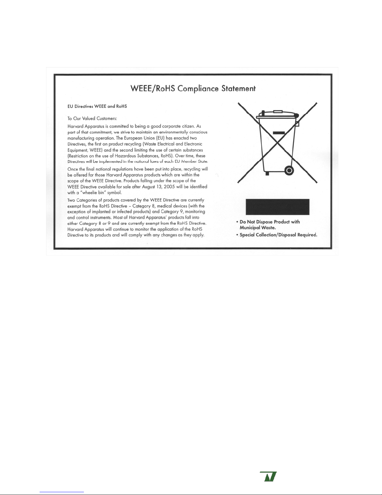
BC-535 Preliminary, Rev. 060126 37
BC-535 Preliminary, Rev. 060126 37
Warner
Warner
A Harvard Apparatus Company .
A Harvard Apparatus Company .
Instruments
Instruments
Page 38

BC-535 Preliminary, Rev. 060126 38
Glossary
A/D converter – Analog to Digital converter. Computers are inherently digital while the voltage or
current output from an amplifier is analog. Therefore, a signal must be first converted to a
digitized form before a computer or its software can accept it. Desirable features in an A/D
converter include rapid signal conversion, small-step resolution and low noise.
analog – Continuous or non-discrete. Often dynamically varying. Compare to: digital.
bandwidth – The range of frequencies a device is capable of processing with minimal distortion. A
bandwidth of 1 Hz indicates that the device can faithfully process a signal occurring once per
second (1 Hz). The larger the bandwidth, the faster the device.
Bessel filter – A device used to attenuate the high frequency components of a signal. The cutoff
frequency of a filter is normally defined as the frequency at which the strength of the signal is
attenuated by 3 dB (10-fold decrease in power). A higher order filter (i.e., 8-pole vs. 4-pole) will
attenuate the high frequency components more rapidly. An 8-pole Bessel filter attenuates at 14
dB per octave.
BLM – Historically, Black Lipid Membrane from the effect of interference at t he upper and lower faces
of the thin film formed resulting in cancellation of all visible wavelengths. When the membrane
thinned appropriately, it would ‘disappear’ or become black. Alternatively, Bilayer Lipid
Membrane. Many researchers now observe membrane formation electrically and have altered the
acronym to mean the molecular bilayer formed from the orientation of lipids such that their polar
heads and hydrophobic fatty acid tails are in register. In an aqueous environment, the polar
heads face away from the membrane leaving the hydrophobic domains within the bilayer.
BNC connector – A type of connector used to connect coaxial cables to high frequency electronic
equipment.
cap comp – See: capacity compensation.
capacitance – A capacitor can be represented by a small break in a conducting pathway bounded by
two parallel plates. The electric field generated across the space between the plates in the
presence of an applied voltage maintains a charge density on each plate. The numerical measure
of a capacitor’s ability to maintain charge separation at a given potential is its capacitance.
Capacitors effectively block DC currents while passing AC currents. Has units of Farad (F).
capacity compensation – The process wherein the current generated when charging a capacitor is
subtracted (or compensated) from the output signal.
channel conductance – See: unitary channel conductance
chassis ground – A connection used to link the amplifier chassis to an external potential.
circuit ground – The potential to which all other potentials within the circuit are referenced. Also, a
connection used to link the reference potential of the amplifier circuit to an externally defined
potential.
Warner
A Harvard Apparatus Company .
Instruments
Page 39

BC-535 Preliminary, Rev. 060126 39
COMMAND IN – Also CMD IN . Command Input. An external input into the BC-535 allowing the application of
user defined command voltages to the headstage. Connection is via BNC.
command sensitivity – Selectable scaling of CMD IN input. Attenuation values of CMD IN are x0.1, x0.01,
and x0.001.
command voltage – The voltage applied to the headstage resulting in a desired transmembrane
potential in the system under study.
control blocks – Organization of controls on the amplifier into functional groups. Blocks are delineated
by titled blue boundaries.
current-voltage relationship – A measure of the way in which the current varies as a function of the
applied voltage. In an Ohmic device (obeys Ohm’s law), this relationship is linear. An
understanding of the current-voltage relationship of a channel yields information about that
channel’s function.
depolarization – A biological membrane in which charge separation has resulted in transmembrane
voltage is termed ‘polarized’. Electrically, depolarization refers to any action which tends to
reduce the degree of polarization. Biophysically, a polarized membrane has a resting
transmembrane potential between –40 and –90 mV, relative to the inside of the cell . An action
which tends to increase the polarization (e.g., increase the transmembrane potential to, say, -100
mV) is termed hyperpolarization, while depolarization refers to any action which decreases the
transmembrane potential. (It should be noted that by this definition, a transmembrane potential
of +100 mV is still depolarized.)
digital – Quantized or discrete. Normally refers to information manipulated by a computer. All
processes within a computer are discrete and are composed of 0’s and 1’s. The universe we
interact with is functionally analog, therefore information we wish to manipulate with a computer
must be digitized prior to use by the computer.
DIN connector – Deutsche Industrie Norm. A German standard for electronic and industrial products.
DIN connectors can be 3 to 6 pin plugs with the same outer diameter and appearance.
electrode – One terminal of a voltage source which can either supply or collect current.
electromagnetic – From physics. An electric current induces a magnetic field and a changing magnetic
field induces an electric current. Therefore, these two entities are related to each other and are
combined into electromagnetism.
electrophysiologist – A scientist who combines the disciplines of physics, electrical engineering, and
physiology to the study biological systems.
Faraday cage – A grounded conducting enclosure which shields its interior from external electric fields.
Named after Michael Faraday, who first described the effect in 1875.
gain – The numerical value of the amplification of a signal by an amplifier. User selectable in the
OUTPUTS block of the amplifier.
gain telegraph – A defined voltage dependent on the gain setting appearing at the associated BNC at
the rear of the amplifier. Used to communicate the gain setting to external devices.
Warner
A Harvard Apparatus Company .
Instruments
Page 40

BC-535 Preliminary, Rev. 060126 40
ground loop – A loop formed from multiple connections into the circuit ground plane by the same
device. The flux of magnetic fields through this loop can induce small currents within the ground
plane resulting in increased noise in the circuit. Careful consideration of the interconnection
between several devices is often required to identify ground loops.
headstage – A low gain amplifier placed as close to the preparat ion as possible. Used to amplify small
currents to a range sufficient for the main amplifier to accept.
– A measure of the current passed through an open channel in the presence of a driving force.
I
m
Operationally, the current appearing at the I
OUTPUT of the amplifier.
m
intracellular – Situated or occurring within a cell.
junction potential – A difference in conductivity between two dissimilar materials will appear as a small
voltage when the two materials are brought into contact. This voltage is termed the junction
potential.
LED – Light Emitting Diode. The red, green or yellow lighted indicators on the front of many devices.
LED’s are preferred indicator light sources due to their low power consumption.
mean closed time – The average length of time a gating channel will remain in the closed state.
mean open time – The average length of time a gating channel will remain in the open state.
mini-jack – A small plug on the headstage to which the electrodes are attached.
model membrane – An electric circuit designed to model the electrical characteristics of a biological
membrane.
open probability – The calculated probability of finding a channel open at time t, given that the channel
is in a closed state at time t=0.
oscilloscope – A device used to monitor voltages within an electrical circuit.
output current – See I
output sync – A pulsed signal appearing at the
synchronize the
m
OUTPUT SYNC BNC on the instrument rear panel. Used to
PULSE GENERATOR or CAP TEST signal to an external device such as an oscilloscope.
periodic – That which repeats itself at regular intervals.
perfusate – The solution being perfused.
perfusion – The exchange of one solution with another.
planar lipid bilayer – See BLM.
plasma membrane – The surface membrane of a cell. Contrast with an intracellular membrane which is
a membrane contained entirely within the cell.
potentiometer – A single- or multi-turn dial used to make a continuously varying selection with a
range. In its heart this is a variable resistor.
pulse code modulator (PCM) – A device which converts an analog signal into a form acceptable for
storage on VCR tape. Also converts data previously stored on VCR tape back into an analog
signal.
Warner
A Harvard Apparatus Company .
Instruments
Page 41

BC-535 Preliminary, Rev. 060126 41
reset – An operation wherein the collected charge on the integrating capacitor in the headstage is
dissipated, readying the system for further use.
signal polarity – Defined as the sign applied to a current generated through a membrane in the
presence of an applied holding potential. The electrophysiological definition is determined by the
membrane such that an outward directed current and a depolarizing potential are both positive.
single channel – Refers to a solitary channel protein functioning within a measurement milieu.
step potential – A functionally instantaneous change in potential from one value to another.
time constant – In a system governed by exponential kinetics this is the time required for a value to
change to 1/e of its initial value, where e=2.71828 is the base of the natural logarithm.
transient – Momentary.
transmembrane – That which spans a membrane or is referred from one side of a membrane to the
other.
trim pot – An adjustable variable resistor used for making fine adjustments to a circuit.
TTL – Transistor, Transistor Logic. Voltage ranges used to define an on or off state in binary devices.
0-0.8 V defines a logic 0 state and 2.4-5.0 V defines a logic 1 state.
unitary channel conductance – A measure of the ability of a channel to pass an ion from one side of the
membrane to the other. An intrinsic property of a single channel which depends on the ionic
species under consideration. Determined by measuring the current through an open channel in
the presence of a driving force (transmembrane potential) at different potentials. Measurements
made within the Ohmic range of the channel’s response will graph as a straight li ne. The slope of
this line when plotted as current (I) vs. potential (V) will yield the conductance (or inverse
resistance) of the channel under these conditions.
hold – The transmembrane potential generated by the amplifier and appl ied to the headstage. This
V
m
driving force appears in addition to any other driving forces which may be present.
– The user selected potential set in the COMMANDS APPLIED TO REFERENCE block of the amplifier.
V
C
Warner
A Harvard Apparatus Company .
Instruments
 Loading...