

Warner Howard c/o PHS Group, Claymore, Tame Valley Industrial Estate, Tamworth, Staffs. B775DQ Tel: 08708504352 Fax: 08708504354 www.phs.co.uk
SERVICING
The filter modules need replacing at the recommended service interval. The filter is removed as
follows.
Press the retaining clip forward to disengage.(Fig.14)
Whilst maintaining pressure on the clip pull the filter downward to remove .(Fig.15)
Replace the 2 filter elements by sliding the filters into position ensuring the clip feature is located.
DESCRIPTION:
High speed hand dryer incorporating Hepa grade filtration for truly clean air. Powered by
universal brush motor, delivering 1100 Watts of drying power. This hand dryer runs on 230
Volts AC electrical supply. An infrared sensor is used to automatically turn the dryer on
and off. This model is intended for use in commercial, industrial, office and public facility
environments.
SPECIFICATION:
Rating: 1100W at 230V ac 50Hz
Construction: ABS
Dimensions (mm): 260x282x152
Weight: 3.2 Kg
IMPORTANT:
This appliance can be used by children aged from 8 years and above and persons
with reduced physical, sensory or mental capabilities or lack of experience and
knowledge if they have been given supervision or instruction concerning use of
the appliance in a safe way and understand the hazards involved.
Children shall not play with the appliance.
Cleaning and user maintenance shall not be made by children without
supervision.
WARNER HOWARD SR1100
Fig.12
Fig.13
Power Plug
Fig.14
Fig.15
051255-A

Fig.1
Fig.3
SITING:
Avoid positioning above lightly coloured or polished surfaces.
Site carefully to avoid causing obstructions.
INSTALLATION:
Remove the cover assembly using the hex key as shown. (Fig.1) Turn the 2 mounting screws fully
clockwise then slide the assembly forward in the direction shown. (Fig.2) The cover assembly can
now be removed from its backplate. (Fig.3)
FIXING
Place the hand dryer base at the desired location. Using the backplate as a template, mark the
position of the four fixing holes (Fig.4). Note; a keyhole slot is provided to aid installation.
Drill the wall to accept the plugs and screws provided. Secure the backplate assembly.
POWER CONNECTOR MODULE
The dryer benefits from a quick-connect power supply system which interfaces with the fixed
backplate. The connector module position is dictated by the backplate. It must be positioned and
secured as shown (Fig.5) to ensure correct cover fitment. Make provision for the electrical supply with
reference to the entry requirement of the power connector module.
POWER CONNECTION MODULE-FITTING
Remove the 2 screws as shown (Fig.6) to release the outer cover.
Remove the terminal connector by sliding upward as shown (Fig.7). This provides access to
securing holes in the module base component.
Position the base component as described previously (Fig.5) and mark the position of the 3
securing holes. Drill the wall to accept the plugs and screws provided. Fix the module base in
position. Ensure that it is secure.
The hand dryer must be connected to the supply via a fused, double-pole isolating switch having a
contact separation of at least 3mm in all poles.
Feed the supply cable through the entry hole in the module base as shown. (Fig.9). Connect the
supply conductors as follows:
BROWN wire to the terminal marked L
BLUE wire to the terminal marked N
NOTE: This is a class 2 insulated product and does not require earth bonding. The terminal connector
has the facility to ‘park’ an earth conductor if one is present.
Re-fit the terminal connector. This is the reverse of removal in (Fig.7). Secure the cable beneath
the cable clamp (Fig.10)
Replace the outer cover and secure using the 2 screws removed previously (Fig.11)
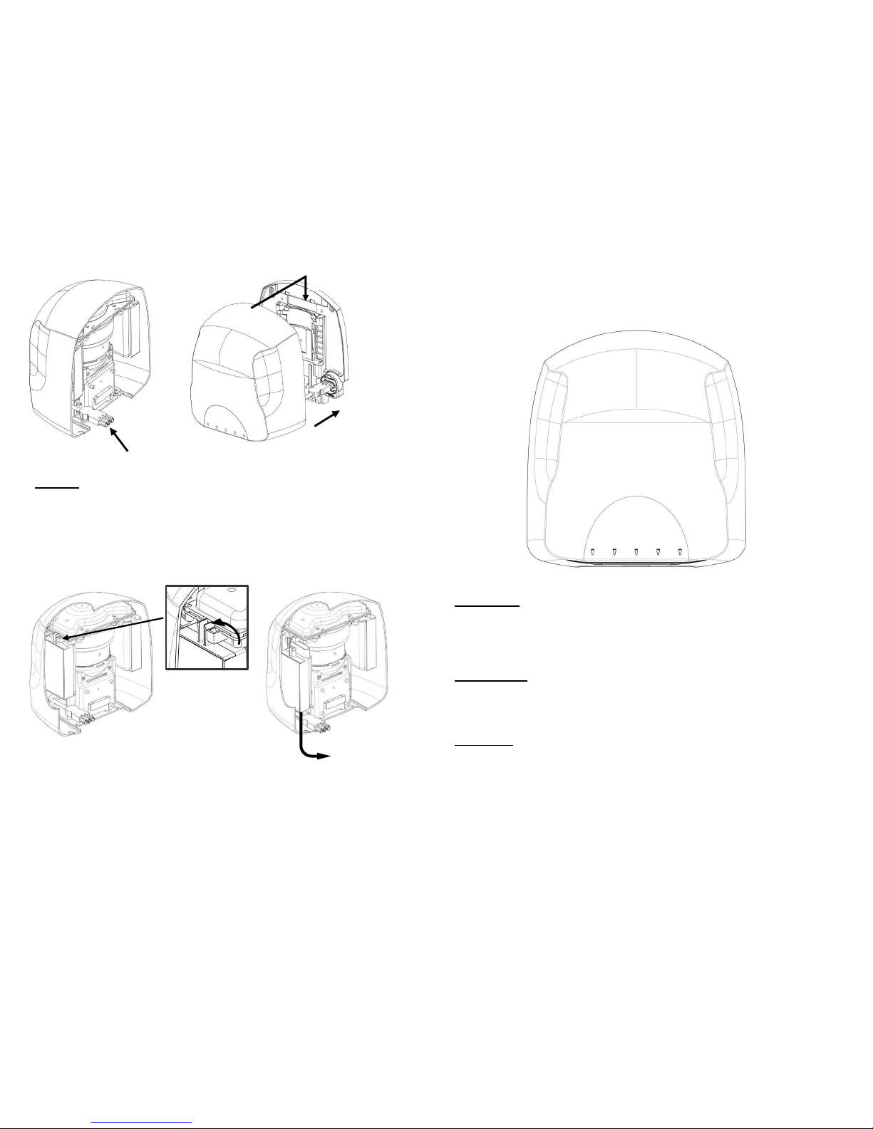
COVER RE-FITTING
Installation can now be completed by making the connection to the power module and replacing the
cover assembly.
Locate the power plug situated inside the cover assembly (Fig.12)
Connect to the terminal in the power connection module (Fig.13)
Locate the cover assembly on the backplate and slide downward into position. This is the
reversal of the installation process in Fig’s 1, 2 & 3.
Secure the cover assembly by rotating the 2 mounting screws anti-clockwise. DO NOT OVER
TIGHTEN.
TESTING
Switch on at the supply
Place hands beneath the dryer. The dryer should start automatically and the cover lights
illuminate.
When the hands are removed the dryer should stop within a few seconds.
Fig.2
Fig.4
Fig.5
Fig.6
Fig.7
Fig.8
Fig.9
Fig.10
Fig.11
Cable entry options. Either
from rear of backplate or
through cover access knockout.
 Loading...