

Page 1
EI1100W INSTRUCTIONS
TABLE 1
Recommended mounting heights from floor to dryer bottom surface (mm)
Men’s Washroom
1168
Women’s Washroom
1118
Children’s Washroom (Aged 4-7)
812
Children’s Washroom (Aged 7-10)
914
Children’s Washroom (Aged 10-14)
1016
Children’s Washroom (Aged 14-17)
1118
Disabled Mounting Height
1016
WARNER HOWARD EL1100W
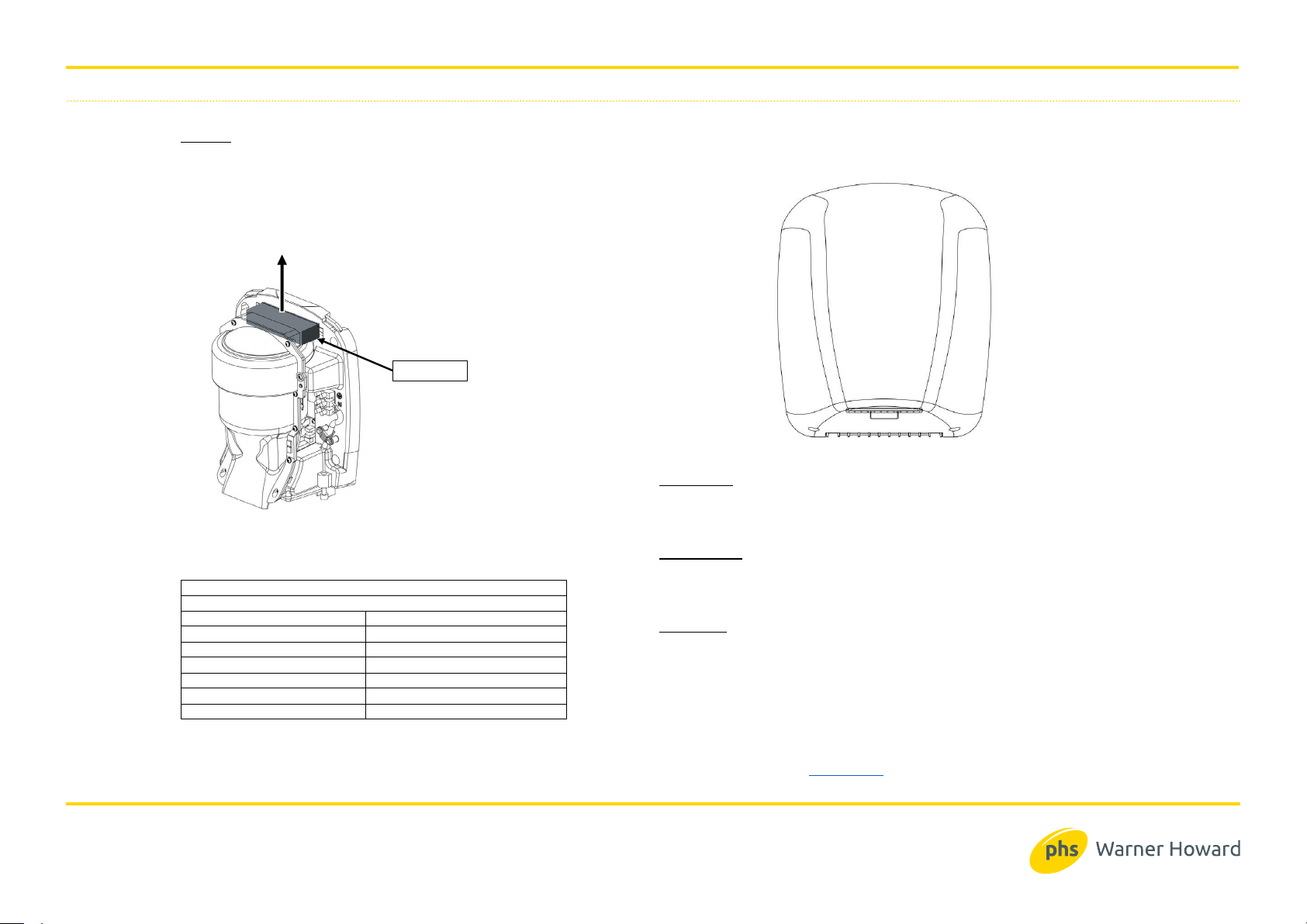
Fig.7
051309-A
SERVICING
Periodic cleaning of the inside of the dryer is recommended to prevent a build-up of dirt and fibres.
With the power disconnected and the cover removed a soft brush can be used to dislodge any debris.
An inlet filter is fitted to prevent debris from entering the motor. This filter can be removed and
replaced by pulling upward as shown. (Fig.7) Replacement is the reversal of removal.
DESCRIPTION:
High speed warm air hand dryer powered by universal brush motor, delivering 1100 Watts
of drying power. This hand dryer runs on 230 Volts ac electrical supply. An infrared sensor
is used to automatically turn the dryer on and off. This model is intended for use in
commercial, industrial, office and public facility environments.
SPECIFICATION:
Rating: 1100W at 230V ac 50Hz
Construction: ABS
Dimensions (mm): 221x268x149
Weight: 2.3 Kg
IMPORTANT:
This appliance can be used by children aged from 8 years and above and persons
with reduced physical,
sensory or mental capabilities or lack of experience and
knowledge if they have been given supervision or instruction concerning use of
the appliance in a safe way and understand the hazards involved.
Children shall not play with the appliance.
Cleaning and user maintenance shall not be made by children without
supervision.
Warner Howard c/o PHS Group, Claymore, Tame Valley Industrial Estate, Tamworth, Staffs. B775DQ Tel: 08708504352 Fax: 087085043 54
www.warnerhoward.co.uk
For further information please contact us on :
Page 2
EI1100W INSTRUCTIONS
Fig.1
Fig.3
Fig.6
Fig.2
Fig.4
Cable entry locations through
base component
Fixing holes
Fig.5
Cable Clamp
N
L
Cable Entry
SITING:
Avoid positioning above lightly coloured or polished surfaces.
Site carefully to avoid causing obstructions.
INSTALLA TION:
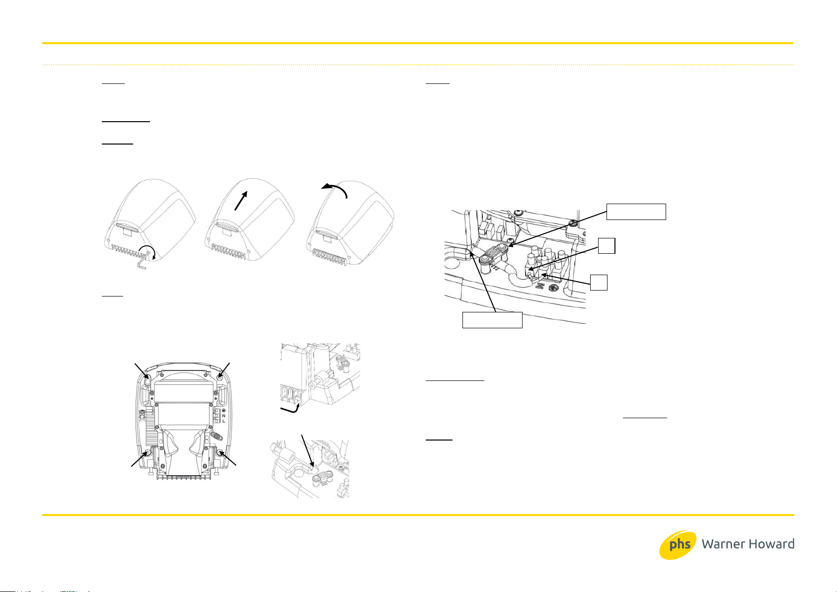
Remove the cover assembly using the hex key as shown. (Fig.1) Turn the 2 mounting screws fully
clockwise then slide the assembly forward in the direction shown. (Fig.2) The cover assembly can
now be removed from its backplate by rotating forward as shown. (Fig.3)
FIXING
Place the hand dryer at the desired location. A guide for recommended mounting height is described
in Table 1. Using the backplate as a template, mark the position of the four fixing holes (Fig.4). Note; a
keyhole slot is provided to aid installation.
Drill the wall to accept the plugs and screws provided. Make provision for the electrical supply.
WIRING
The hand dryer must be connected to the supply via a fused, double-pole isolating switch having a
contact separation of at least 3mm in all poles.
Feed the supply cable through the entry hole in the dryer base as shown. (Fig.5).
Attach the dryer to the wall ensuring that it is secure.
Connect the supply conductors as follows:
BROWN wire to the terminal marked L
BLUE wire to the terminal marked N
Secure the cable beneath the cable clamp. Ensure that the clamp bears only on the outer
sheathing (Fig.6)
NOTE: This is a class 2 insulated product and does not require earth bonding. The terminal connector
has the facility to ‘park’ an earth conductor if one is present.
COVER RE-FITTING
Installation is now complete and the cover should be replaced.
Locate the cover assembl y onto the backplate and slide downward into position. This is the
reversal of the installation process in Fig’s 1, 2 & 3.
Secure the cover assembly by rotating the 2 mounting screws anti-clockwise. DO NOT OVER
TIGHTEN.
TESTING
Switch on at the supply
Place hands beneath the dryer. The dryer should start automatically.
When the hands are removed the dryer should stop within a few seconds.
For further information please contact us on :
 Loading...