

Page 1

Electromagnetic Particle Clutches
Models: PMC-10A3, PMC-20A3, and PMC-40A3
P-223-2
819-0369
Installation Instructions
Page 2
2
Warner Electric • 800-825-9050 819-0369
Contents
Introduction . . . . . . . . . . . . . . . . . . . . . . . . . . .2
Installation Instructions . . . . . . . . . . . . . . . . . .2
Electrical Data . . . . . . . . . . . . . . . . . . . . . . . . .4
Mechanical Data . . . . . . . . . . . . . . . . . . . . . . .4
Start Up . . . . . . . . . . . . . . . . . . . . . . . . . . . . . .4
Maintenance . . . . . . . . . . . . . . . . . . . . . . . . . .5
PMC-10 and 20 Dimensions . . . . . . . . . . . .5-6
PMC-40 Dimensions . . . . . . . . . . . . . . . . . . . .7
Warranty . . . . . . . . . . . . . . . . . . . . .Back Cover
Introduction
This service manual provides information
required for the installation, wiring, and maintenance of Warner Electric's Magnetic Particle
Micro Clutch series. It also includes dimensions
and specifications. The three models covered in
this service manual are PMC-10A3, PMC-20A3,
and PMC-40A3. These models with their flanged
input hubs, also lend themselves to be mounted
as brakes. For selection information, please refer
to your Warner Electric Tension Control Systems
Catalog.
Warner Electric's Magnetic Particle clutches
provide smooth and controllable torque for a
variety of applications, including tension control,
cycling, and positioning. Quick response is
achieved by applying full rated voltage. Lower
voltage can be applied for softer engagements.
Extremely accurate tension control can be
achieved when these brakes are used with one
of Warner Electric's wide range of tension controls for electric clutches.
Failure to follow these
instructions may result in product damage,
equipment damage, and serious or fatal
injury to personnel.
Installation Instructions
Introduction
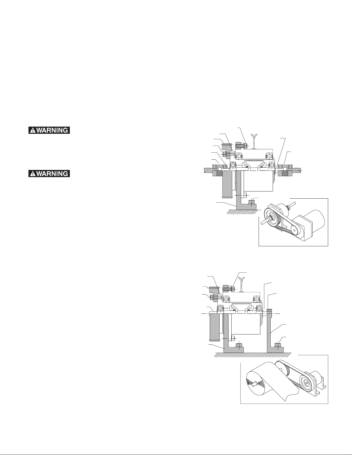
The design of the PMC-A3 series clutches
makes them easy to mount in various configurations. They have a mounting flange on the outside diameter of the housing. The input is a
flanged hub, which is concentric to the double
ended output shaft. See Figure 1 for typical
mounting. To use the PMC-A3 as a brake, the
output shaft must be secured. See Figure 2.
Make sure all power is turned
off to this equipment when installing, as
injury (or even death) may result from contact
with live wires or rotating shafts.
Mounting bracket
Mounting bracket
Capscrews
Socket
head cap
screws
Set screws
Input hub
Timing pulley
Output shaft
Capscrews
Output shaft
Socket
head cap
screws
Input hub
Timing pulley
Output shaft
Capscrews
Flexible
coupling
Mounting
Bracket
Capscrews
Flexible
coupling
Output shaft
Figure 2* - Mounted as a brake
*Note: Shaded items are customer supplied
Figure 1* - Mounted as a clutch
Page 3

3
Warner Electric • 800-825-9050 819-0369
Pre-Mounting
Note: Unit performance can be affected by
prolonged exposure to humid environments.
Please store in a dry location.
Note: The equipment covered by this service
manual must be installed in accordance with
these instructions. Failure to do so may damage the equipment and void the warranty.
1. Remove the magnetic particle clutch from its
shipping carton and inspect it thoroughly to
ensure that it has arrived in good condition.
When handling, please take care not to damage lead wires.
2. Check the input hub to make sure it turns
freely when the output shaft and housing are
held stationary. The powder inside the unit
may settle due to shock and vibration caused
during shipping. This can make rotation
noticeably difficult and can be easily remedied by turning the unit upside down and
gently tapping the outside to loosen the powder.
3. Make sure the location chosen for mounting
will not expose the unit to water or oil. If
water or oil gets into the powder cavity, the
performance of the unit may be affected. If
the unit is mounted next to a gearbox, special care should be taken to prevent oil from
working its way into the unit.
4. If couplings are used to make drive system
connections, the mounting surface must
properly locate the housing to ensure that
alignment is within the coupling manufacturer's specifications.
Mounting
Note: Do not use excessive force when mount-
ing couplings, pulleys, or sprockets on shafts.
Note: For proper function, mount magnetic
particle units horizontally.
For mounting dimensions, please refer to pages
5-7 of this service manual.
As A Clutch
Step 1: Bolt Unit in Place
Mount the unit to a vertical surface, using customer supplied fasteners. See Figure 1.
Step 2: Make Mechanical Connections
Mount couplings, pulleys, or sprockets to the
male shafts per the manufacturer's recommendations. The pulleys, sprockets, couplings,
mounting brackets, and bolts are customer supplied. (The output shaft can be used as the input
and the input hub as the output, but the output
inertia will be higher.)
As A Brake
Step 1: Bolt Unit Into Place
Secure the mounting flange and the output shaft
as shown in Figure 2. Take care to insure that
alignment is true and there is no binding in the
bearings.
Step 2: Mount Pulley, Sprocket, or Coupling
Bolt the pulley, sprocket, or coupling to the
input hub of the unit. The pulleys, sprockets,
couplings, mounting brackets and bolts are customer supplied.
Page 4

Mechanical Data
Drag Maximum Inertia
Unit Part Torque Torque Speed Input Output Weight
Number (lb. in.) (lb. in.) (rpm) (in. lb.2) (in. lb.2) (lbs.)
PMC-10A3 5401-270-111 8.6 .25 1800 .239 .0291 2.0
PMC-20A3 5401-270-121 17 .51 1800 .413 .0752 2.9
PMC-40A3 5401-270-131 34 1.0 1800 1.14 .372 5.5
4
Warner Electric • 800-825-9050 819-0369
Electrical Connections
To avoid injury (or even death),
always make certain all power is off before
attempting to install or service the control or
any electrical equipment.
The PMC-A3's operate on DC voltage. Warner
Electric offers a full line of AC powered controls
to meet the needs of almost every application.
The service and installation instructions included
with each Warner Electric control show the
proper electrical connections.
After wiring your Magnetic Particle unit, confirm
that the control circuit is functioning. Without
rotating the input shaft, verify that voltage is
applied when the control output is turned on.
Also, if appropriate, set the current for the proper output. Your magnetic particle unit is now
ready for operation. For information on start up
and maintenance, see page 4 of this manual.
Electrical Data
Electrical Coil Data
To rque Torque
Unit Size Voltage Resistance Amperes Watts Build Up Decay
[ohms @ 75°F (25°C)] [@ 75°F (25°C)] [@ 75°F (25°C)] (msec) (msec)
10 24 35.1 0.684 16.4 20 8
20 24 31.6 0.760 18.2 30 10
40 24 26.3 0.912 21.9 40 12
Note: Build up time equals time for torque to build to approximately 63.2% of steady state value
after a step change in voltage. Decay time equals time for current to drop to approximately 36.8%
of the steady state value after a voltage change.
Start Up
The powder in the magnetic particle units sometimes settles during shipment and will need to
be redistributed. A simple run-in procedure
should be performed to ensure proper performance.
Run in Procedure
Notes: 1. Before running in, make sure the unit
does not bind. See step 2 of the premounting instructions.
2. If mounted as a clutch, the output
shaft must be locked to prevent it
from turning.
Set the control output voltage for 5 to 6 volts.
Turn off the control and run the input for one
minute. Run at a speed close to, but not
exceeding 1000 RPM. Then cycle the unit at 5
or 6 volts for five seconds and off for ten seconds. Repeat this for 20 cycles.
When the powder is redistributed properly, the
torque will be consistent and proportional to
current.
Page 5

5
Warner Electric • 800-825-9050 819-0369
Maintenance
Heat
Make sure your unit does not overheat. This
occurs when the heat generated is greater than
the heat dissipation capability of the unit. The
maximum allowable surface temperature for the
PMC-A3 series unit is 167° F.
Slip Applications
With most controls, torque is easily adjusted.
However, care must be taken when adjusting
torque to make sure that too much heat is not
generated in the unit. The heat generated is proportional to torque and slip rpm. Refer to the
sizing procedure in the catalog to make sure the
unit has adequate heat dissipation capability.
Also, do not increase the slip speed or the
torque without verifying that the unit can dissipate the heat.
Cycling Applications
In cycling applications, the speed and inertia of
the load and the cycle rate determines the heat
generated. Refer to the selection procedure in
the catalog to verify that the unit can handle the
thermal energy generated in your application.
Also, do not increase the speed, cycle rate, or
inertia without checking the units ability to dissipate the heat generated.
Contamination
Do not expose the unit to water or oil. If water
or oil gets into the powder cavity, the performance of the unit may be affected. If the unit is
mounted next to a gearbox, special care must
be taken to prevent oil from working its way into
the unit.
PMC-10A3 and PMC-20A3 Dimensional Data
Note: All dimensions are nominal unless otherwise noted.
Model A B C D E F G H I J K L M N
mm mm mm mm mm mm mm mm mm mm mm mm mm mm
(in.) (in.) (in.) (in.) ((in.) (in.) (in.) (in.) (in.) (in.) (in.) (in.) (in.) (in.)
PMC-10A3 58 77 14 4 15 12 12 8 6 10 10 51 76 30
(2.28) (3.03) (0.55) (0.16) (0.59) (0.47) (0.47) (0.31) (0.24) (0.39) (0.39) (2.01) (2.99) (1.18)
PMC-20A3 69 116 33 4 22 25 24 15 6 20 20 51 92 35
(2.72) (4.57) (1.30) (0.16) (0.87) (0.98) (0.94) (0.59) (0.24) (0.79) (0.79) (2.01) (3.62) (1.38)
Shaft Dimensions U V
PQRST
Thread Thread Bolt Hole Bolt
Size Depth Circle Size Circle
mm (in.) mm (in.) mm (in.) mm mm mm mm mm mm
(in.) (in.) (in.) (in.) (in.) (in.)
54.000
2.1260 58.000 2.2835 7.000 0.2756 6—M46464.5 68
53.970 2.1248 57.970 2.2823 6.985 0.2750 0.24 — (0.24) (1.81) (0.18) (2.68)
54.000
2.1260 69.000 2.7165 12.000 0.4724 11.5 11.5 M4 6 46 4.5 82
53.970 2.1248 68.970 2.7154 11.988 0.4720 (0.45) (0.45) (0.24) (1.81) (0.18) (3.23)
Page 6

6
Warner Electric • 800-825-9050 819-0369
Dimensions
Lead Wire
Length = 300mm
V
- 4 through holes
U
- 4 threaded holes
R
(11.8 inches)
T
S
Output shaftboth ends
Q
P
K
F
E
I
D
B
G
J
M
A
N
L
H
C
PMC – 10 & 20
Page 7

7
Warner Electric • 800-825-9050 819-0369
Lead Wire
Length = 300mm
4-ø 4.5 (0.18)
on a 100 (3.94) B.C.
(11.8 inches)
12.018
12.000
0.4731
0.4724
()
4-M4 T 6 (0.24) on a 60 (2.36) B.C.
112
(4.41)
Hollow output
shaft - both ends
86.000
85.965
3.3858
3.3844
()
70.000
69.970
2.7559
2.7547
()
20
(0.79)
4
(0.16)
59
(2.32)
86
(3.39)
50
(1.97)
97
(3.82)
21
(0.83)
8.7
(0.34)
10
(0.39)
22
(0.87)
4
(0.16)
15
(0.59)
6
(0.24)
PMC – 40
Dimensions
Page 8

Warranty
Warner Electric LLC warrants that it will repair or replace (whichever it deems advisable) any
product manufactured and sold by it which proves to be defective in material or workmanship
within a period of one (1) year from the date of original purchase for consumer, commercial or
industrial use.
This warranty extends only to the original purchaser and is not transferable or assignable without
Warner Electric LLC’s prior consent.
Warranty service can be obtained in the U.S.A. by returning any defective product, transportation
charges prepaid, to the appropriate Warner Electric LLC factory. Additional warranty information
may be obtained by writing the Customer Satisfaction Department, Warner Electric LLC, 449
Gardner Street, South Beloit, Illinois 61080, or by calling 815-389-3771.
A purchase receipt or other proof of original purchase will be required before warranty service is
rendered. If found defective under the terms of this warranty, repair or replacement will be made,
without charge, together with a refund for transportation costs. If found not to be defective, you
will be notied and, with your consent, the item will be repaired or replaced and returned to you
at your expense.
This warranty covers normal use and does not cover damage or defect which results from
alteration, accident, neglect, or improper installation, operation, or maintenance.
Some states do not allow limitation on how long an implied warranty lasts, so the above limitation
may not apply to you.
Warner Electric LLC’s obligation under this warranty is limited to the repair or replacement of the
defective product and in no event shall Warner Electric LLC be liable for consequential, indirect,
or incidental damages of any kind incurred by reason of the manufacture, sale or use of any
defective product. Warner Electric LLC neither assumes nor authorizes any other person to give
any other warranty or to assume any other obligation or liability on its behalf.
WITH RESPECT TO CONSUMER USE OF THE PRODUCT, ANY IMPLIED WARRANTIES WHICH
THE CONSUMER MAY HAVE ARE LIMITED IN DURATION TO ONE YEAR FROM THE DATE OF
ORIGINAL CONSUMER PURCHASE. WITH RESPECT TO COMMERCIAL AND INDUSTRIAL
USES OF THE PRODUCT, THE FOREGOING WARRANTY IS IN LIEU OF AND EXCLUDES ALL
OTHER WARRANTIES, WHETHER EXPRESSED OR IMPLIED BY OPERATION OF LAW OR
OTHERWISE, INCLUDING, BUT NOT LIMITED TO, ANY IMPLIED WARRANTIES OF
MERCHANTABILITY OR FITNESS.
Some states do not allow the exclusion or limitation of incidental or consequential damages, so
the above limitation or exclusion may not apply to you. This warranty gives you specic legal
rights and you may also have other rights which vary from state to state.
Changes in Dimensions and Specifications
All dimensions and specications shown in Warner Electric catalogs are subject to change without
notice. Weights do not include weight of boxing for shipment. Certied prints will be furnished
without charge on request to Warner Electric.
Warner Electric LLC
31 Industrial Park Road • New Hartford, CT 06057
815-389-3771 • Fax: 815-389-2582
www.warnerelectric.com
P-223-2 819-0369 6/05 Printed in USA
 Loading...