

Page 1
Primary Clutch/Brake Pin Drive, Spline Drive
PCB-825, PCB-1000, PCB-1225
Primary Clutch/Brake Coupling
PCBC-825, PCBC-1000, PCBC-1225
P-205
819-0474
Installation Instructions
Page 2
Contents
Installation Instructions
PCB-825, PCB-1000, PCB-1225 . . . . . . . . . . . . . . .3
Pin Drive Armature
PCB-825, PCB-1000, PCB-1225 . . . . . . . . . . . . . . .8
Spline Drive Armatures
PCBC-825, PCBC-1000, PCBC-1225 . . . . . . . . . . . .9
Coil Data . . . . . . . . . . . . . . . . . . . . . . . . . . . . . . . . .14
Burnishing and Maintenance . . . . . . . . . . . . . . . .14-15
Illustration Drawings
PCB-825, PCB-1000, PCB-1225 . . . . . . . . . . . . . .16
Pin Drive
PCB-825, PCB-1000, PCB-1225 . . . . . . . . . . . . . .22
Spline Drive
PCBC-825, PCBC-1000, PCBC-1225 . . . . . . . . . . .28
Bushing Part Numbers . . . . . . . . . . . . . . . . . . . . . . .34
Warranty . . . . . . . . . . . . . . . . . . . . . . .Back Page
Follow the installation instructions in this manual carefully to ensure safe,
reliable operation. All stated or implied manufacturer warranties are voided if this product is not installed in accordance with these
instructions.
Failure to follow these
instructions may result in product damage, equipment damage, and serious or
fatal injury to personnel.
PCB-825 PCBC-825
Pin Drive Spline Drive
Warner Electric • 800-234-3369 P- 205-01 • 819-0474
2
Page 3
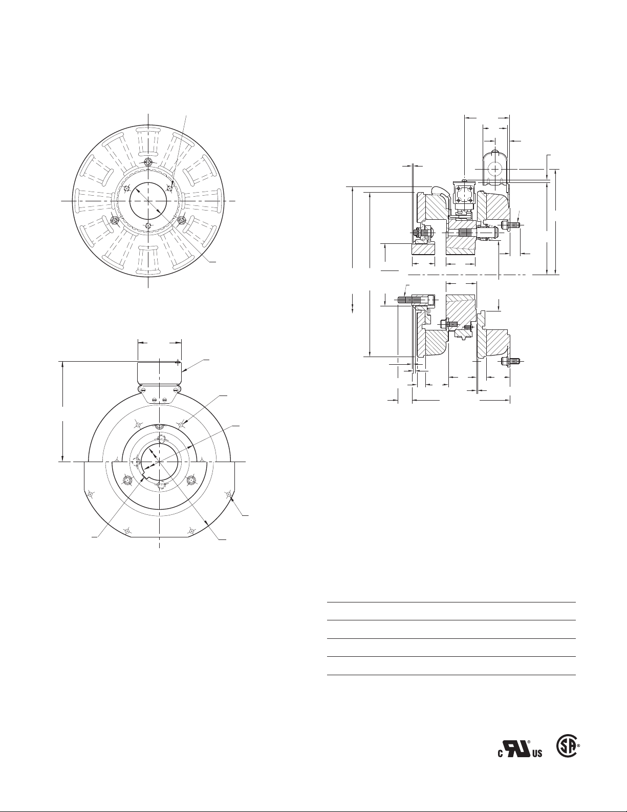
Clutch-Brake Pin Drive Armatures
Field
Pilot diameter
Mounting Surface
PCB-825 PCB-1000 PCB-1225
The illustration drawings, parts lists, and exploded
views for these units can be found starting on
page 16.
The brake half of the clutch/brake unit is usually
installed first; however, in some cases it may be
necessary to start with the clutch portion of the
unit to assure a proper assembly when complete.
A. Installing the Conduit Box
Install the conduit box on the brake magnet.
Instructions for this procedure can be found with
Conduit Box.
B. Mounting the Brake Magnet
The brake magnet is mounted to a stationary
machine member by a flange. Extreme care must
be taken in selecting the location for the mounting
of the magnet. Proper positioning is very important
for the unit to function correctly.
2. A machined pilot diameter is provided on the
magnet mounting flange (refer to illustration
drawings) to aid in the proper positioning of the
magnet.
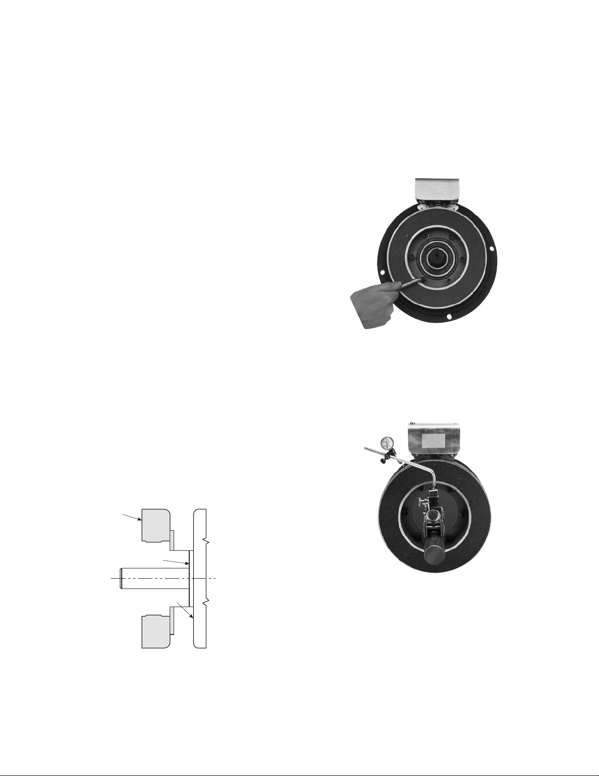
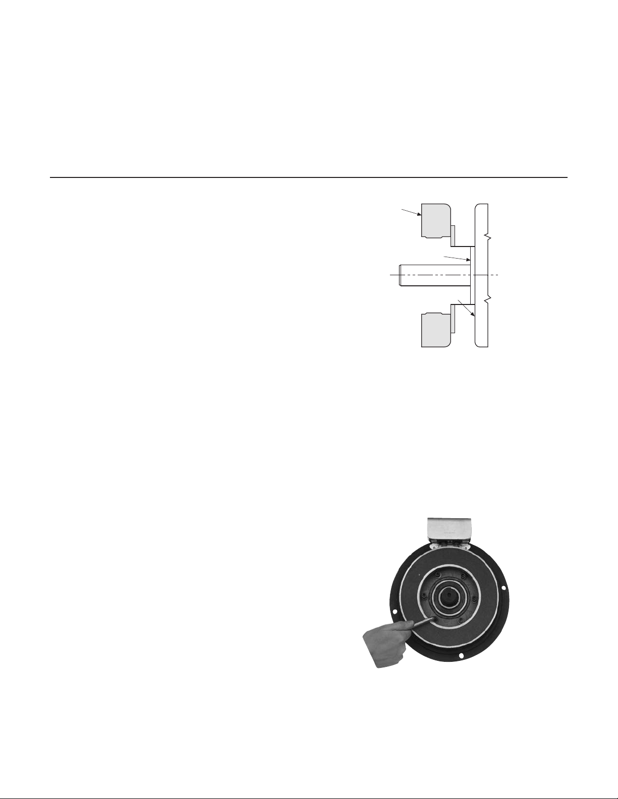
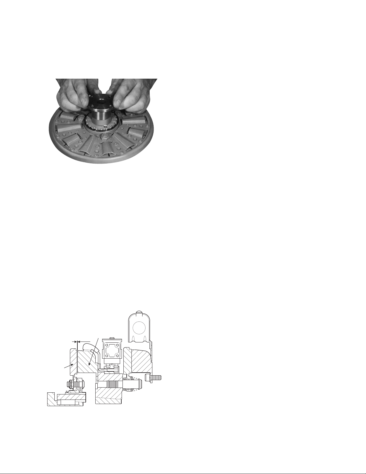
3. Once the mounting surface has been prepared,
the magnet is bolted in place with capscrews
and lock-washers. (Figure 2)
Figure 2
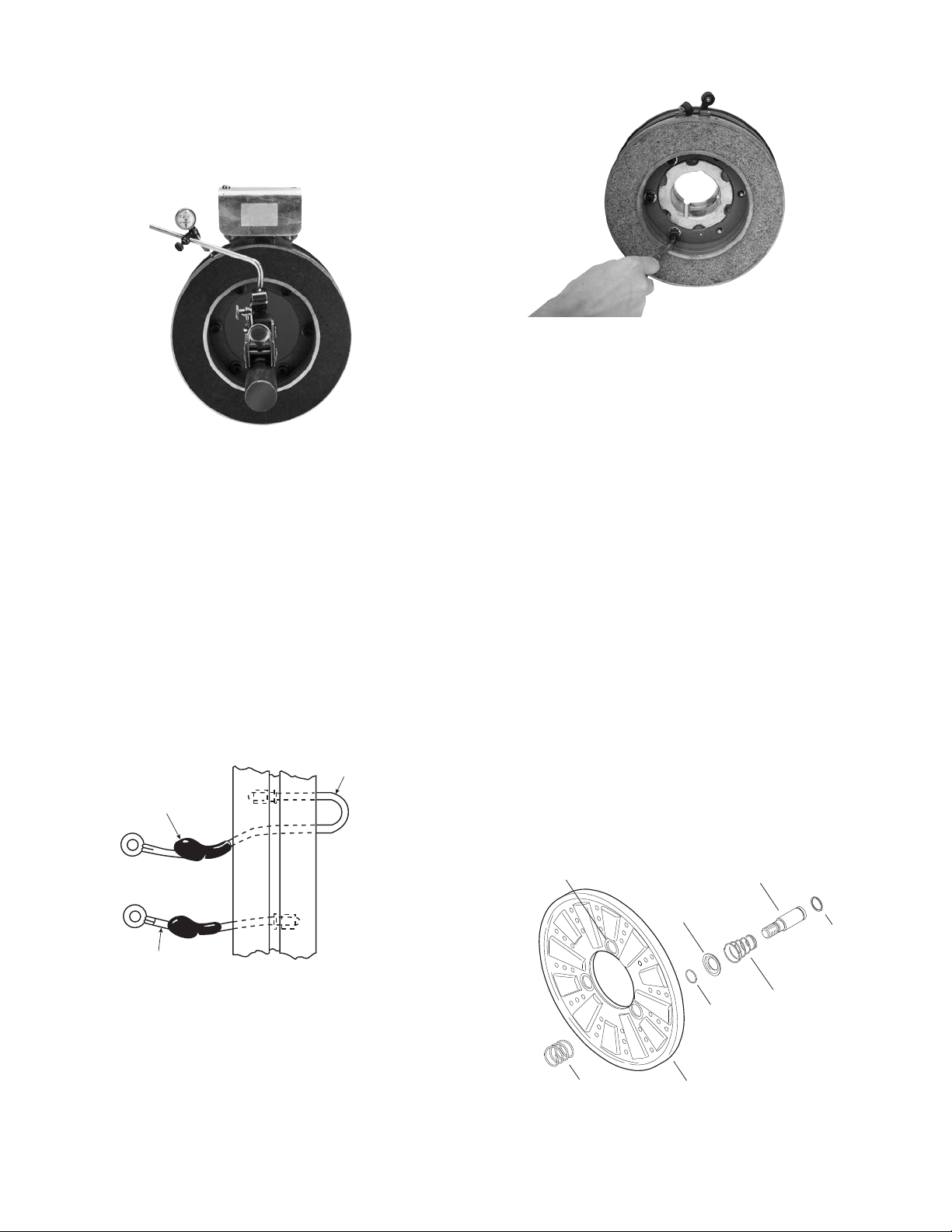
4. Use a dial indicator to check the unit for
concentricity and squareness to the shaft. The
unit should be concentric within .010 T.I.R. and
square within .006 T.I.R. (Figure 3)
1. A pilot diameter on the mounting surface is
essential to hold the magnet within the required
tolerances. (Figure 1)
Figure 3
Figure 1
Warner Electric • 800-234-3369 P-205-01 • 819-0474
3
Page 4
C. Assembling the Clutch Magnet and
Short
Wire
Collector
Ring
Terminal
Cap
Long
Wire
Armature Boss
Straight Spring
(White)
Detent Spring
Retainer
Retainer
Ring
Detent
Spring
Drive Pin
Heavy
Spring
(Red)
Armature
Magnet Hub
D. Assembling the Brake Armature and
Magnet Hub
1. Insert the lead wires through the rubber terminal caps and into the collector ring. The shorter
wire goes into the hole in the front of the ring
(the side that will be mounted to the magnet).
The longer wire goes through the ring and into
the hole in the back.
Press the bullet-type connectors firmly into
place. (Figure 4)
Figure 4
2. Mount the magnet to the magnet hub using
capscrews and lockwashers. (Figure 5)
Assemble the armature to the magnet hub with the
autogap mounting accessory.
The autogap accessory is a double spring device
which allows for automatic armature clearance and
adjustment for wear. The smaller or conical spring
pushes the armature from the magnet face, leaving a
gap of about 1/32 inch, while the straight spring
automatically follows up for wear. This combination
maintains maximum performance efficiency
throughout the life of the unit.
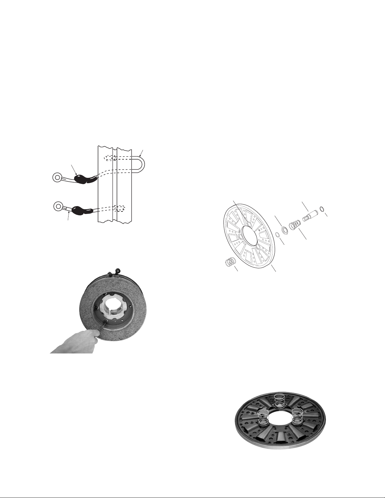
The assembly procedure for the autogap accessory
is as follows. (Figure 6)
4
Figure 6
Note: The 1225 unit is mounted with four drive
pins instead of three as shown in the pictures;
however, the assembly procedure is the same for
either case.
Figure 5
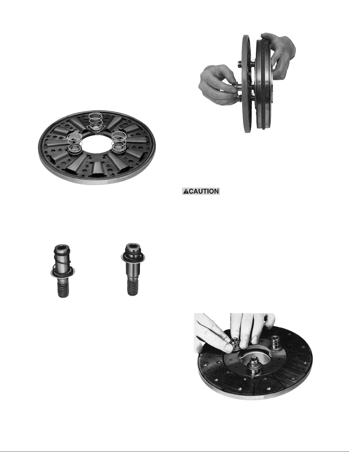
Step 1
Place straight springs (white) over armature bosses
3. Secure the lead wires to the magnet terminals
on back side of armature. (Figure 7)
with screws and lockwashers.
4. Pull the rubber caps over the terminals.
Warner Electric • 800-234-3369 P- 205-01 • 819-0474
Figure 7
Page 5
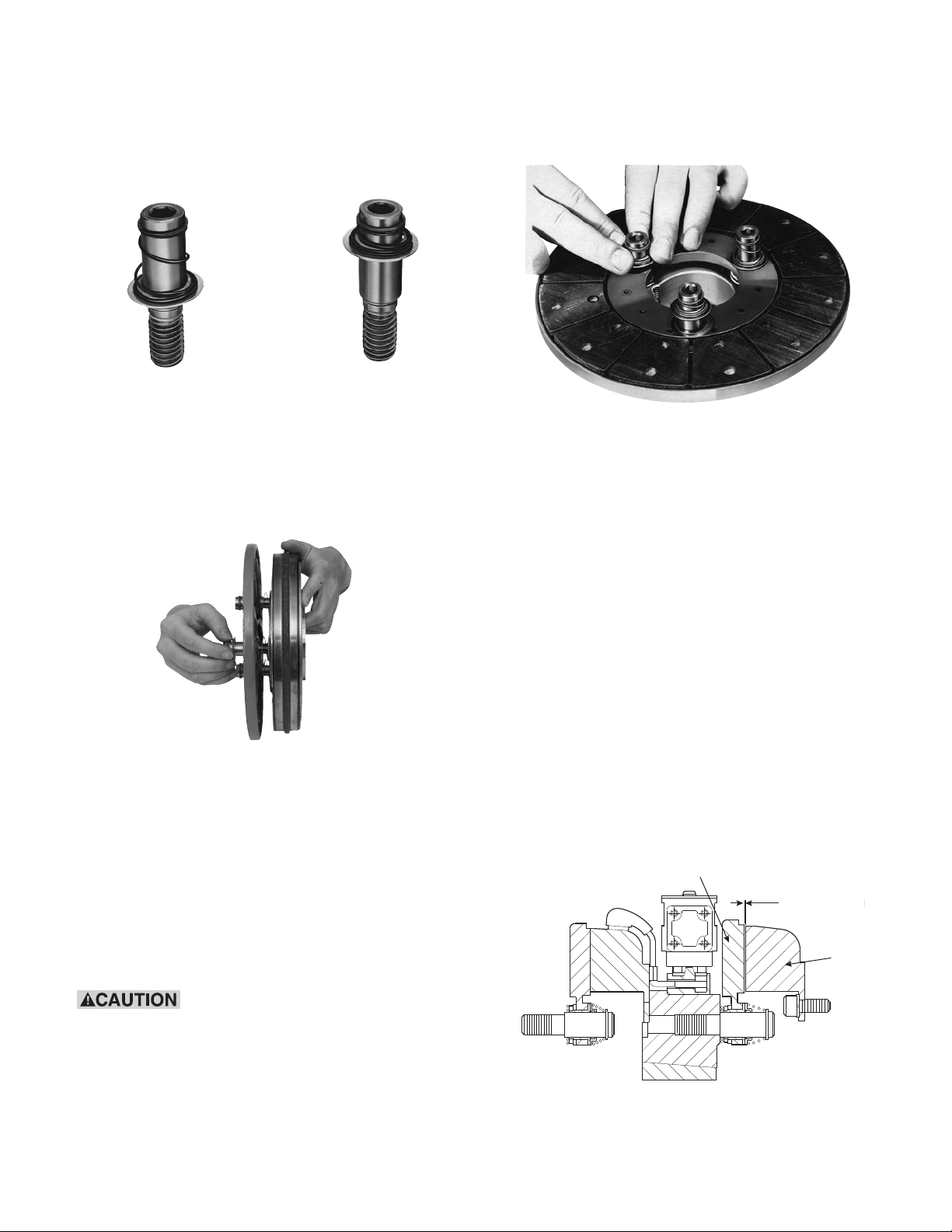
Step 2
Armature
Brake
1/32-inch Gap
Compress the heavy (red) spring on each drive pin
by sliding detent spring towards head of pin.
(Figure 8)
Figure 8
Step 6
To set the autogap, slide the detent spring retainers
against the armature face. (Figure 10)
Step 3
Insert assembled drive pins through armature
(entering from segmented side), through straight
(white) springs, and into magnet hub. (Figure 9)
Figure 9
Note: Apply Grade "AA" Loctite® Sealant on
pin threads.
Figure 10
Note: This position must not be disturbed during
completion of assembly.
E. Mounting the Magnet-Hub-Armature
Assembly
This assembly is mounted on the shaft with a
taperlock bushing. All parts must be clean and free
from burrs and chips before assembling.
1. Place the bushing into the hub, and insert the
key. The key is a side-to-side fit and should not
contact the top of the keyway.
2. Insert the locking setscrews loosely into the
bushing, and slide the assembly onto the shaft.
Step 4
Tighten pins until shoulders of pins are against
face of hub. Since threads are class No. 3 fit, pins
may seem to bind.
Straight springs must not get
caught under shoulders of drive pins.
Step 5
Check to see that the armature is completely
compressed against the face of the hub.
Warner Electric • 800-234-3369 P-205-01 • 819-0474
Figure 11
5
Page 6
3. Position the assembly to allow a gap of about
A
C
D
B
1-9/32"
5/16"
2-1/4"
1/2"–13 UNC–3A
Threads
+.0005"
.6185"
Dia.
–.0010"
1/32-inch between the brake magnet and
armature faces. (Figure 11)
Once this gap is set, it will be automatically
maintained for the life of the unit.
4. Secure the assembly in this position on the
shaft by alternately tightening each setscrew.
During the tightening process, the bushing
should be tapped lightly to make certain it
seats-in properly.
Note: For pin drive armatures (normal duty),
continue to F. For spline drive armatures (heavy
duty), proceed to F. on page 8.
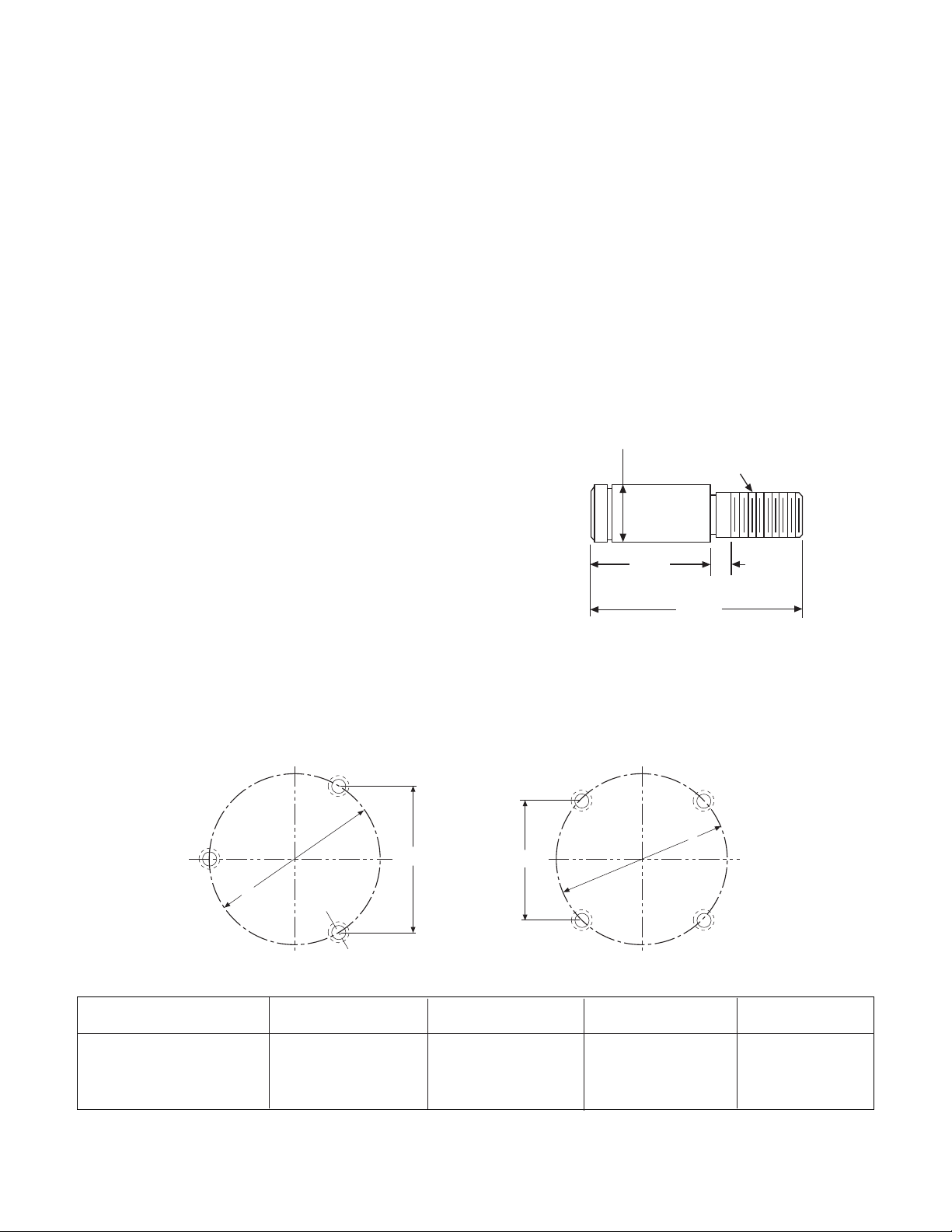
F. Assembling the Clutch Armature
1. A customer may wish to use the autogap
accessory to mount a clutch armature to his
own pulley, hub, gear, etc. Follow the
illustrated dimensions (Figures 12 & 13) to
properly adapt these parts to the armature.
a. Chordal dimensions "A" and "C" must be
held for all chords between pin holes.
b. Drill 27/64-inch diameter holes to a suffi-
cient depth and tap for 1/2-13 NC-3
1-1/8-inch minimum full threads. Pin holes
must be square with plane of mounting surface and magnet mounting.
c. Ream .501/.500 to a 3/8-inch depth and to
be concentric with tapped holes.
Machining Instructions for Gear, Sprocket, or Pulley
Unit Size AB C D
825 3.085 ± .001 3.563 ± .001
1000 4.548 ± .002 5.252 ± .002
1225 4.155 ± .002 5.877 ± .002
Figure 12
Figure 13
Warner Electric • 800-234-3369 P- 205-01 • 819-0474
6
Page 7
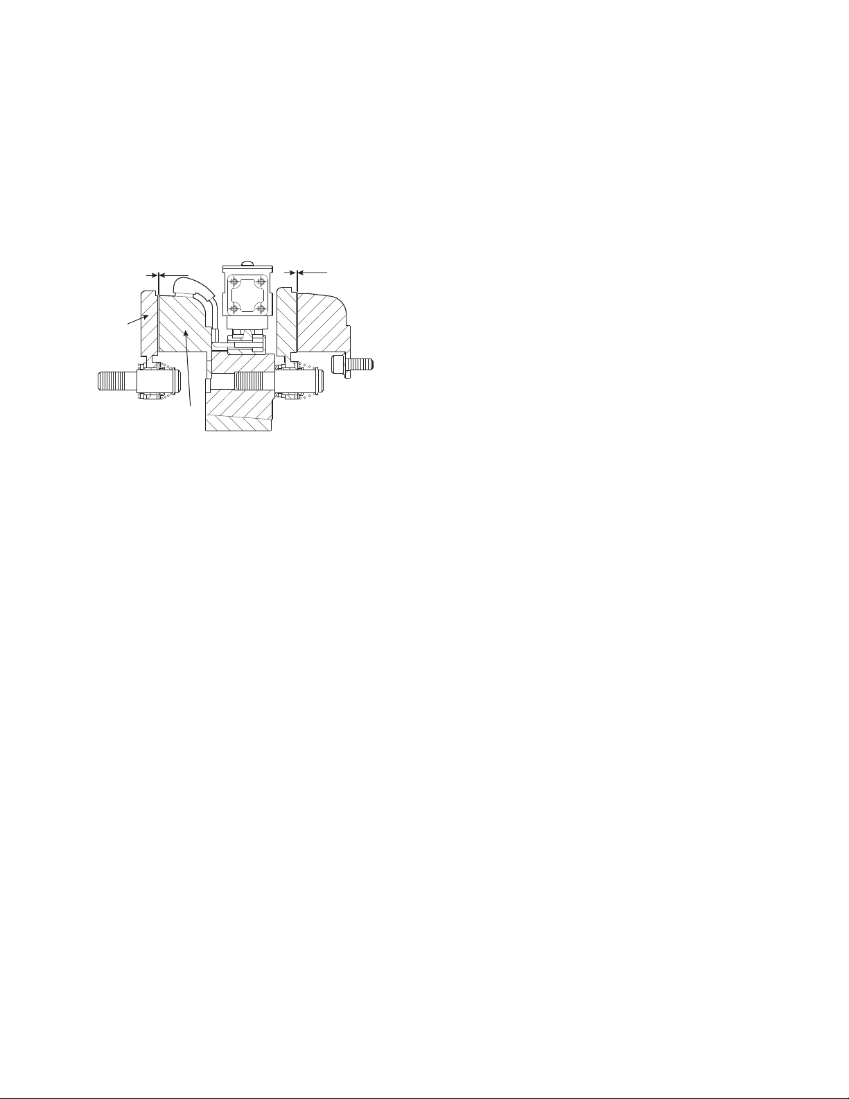
2. Once the pulley, gear, etc., has been adapted
Armature
Clutch
Magnet
1/32-inch G
1/32-inch Gap
to the armature according to the above
directions, it may be mounted to the armature
using the autogap accessory.
The procedure is the same as described for the
brake armature on page 3.
Figure 14
H. Mounting the Brushholder
1. The brushholder is mounted on a bracket
which must be furnished by the customer.
The bracket must be firmly secured to
prevent vibration which could cause
improper contact between the brushes
and collector ring.
2. The distance from the centerline of the shaft
to the top of the brushholder should be
5-3/4". Maintaining this distance will assure
proper spring tension on the brushes and
maximum wear follow-up. A detailed
dimensional drawing is included with
each brushholder.
G. Mounting the Clutch Armature
1. Slide the armature and customer supplied
pulley sprocket or hub assembly onto the shaft.
2. Adjust the armature's position to allow a 1/32"
gap between the magnet and armature faces.
(Figure 14)
Once this gap is set, it will be automatically
maintained for the life of the unit.
3. The armature and customer supplied pulley,
sprocket or hub assembly can be held in
position on the shaft by (a) retainer rings, (b)
set collars, (c) a shoulder on the shaft, or (d)
any combination of these. The best method
will depend on the characteristics of each
application.
Warner Electric • 800-234-3369 P-205-01 • 819-0474
7
Page 8
Armature
1/32-inch Gap
Clutch
Magnet
PCB-825 PCB-1000 PCB-1225
Clutch-Brake Spline Drive Armature
The illustration drawings, parts lists, and exploded
views for these units can be found beginning on
page 22.
Refer to the installation instructions for pin drive
armature units, page 3, for steps A-E.
F. Assembling the Spline Drive Armature
2. A customer may mount the clutch armature to
his own pulley, hub, gear, etc. Refer to the
illustration drawings, "Armature View," for the
dimensional information needed to drill and tap
holes in the customer part.
The splined hub pilot diameter must be
concentric with the splined armature center of
rotation within .010 T.I.R.
3. Mount the armature to the customer's part using
the capscrew accessory provided.
1. These clutch-brake units contain spline drive
armatures and hubs. The armatures are shipped
with a built-in autogap spring accessory. This
device automatically maintains a gap of about
1/32 inch between the armature and magnet
faces for the life of the unit.
The spline drive armature assembly is shipped
with the armature, splined armature adapter,
and autogap already assembled. The splined
hub and capscrew accessories are shipped as
separate parts.
Follow these instructions to assemble the
splined armature assembly and hub:
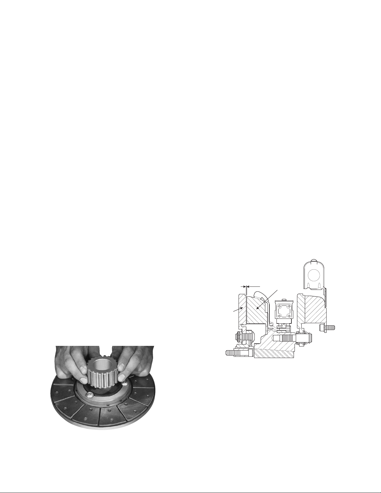
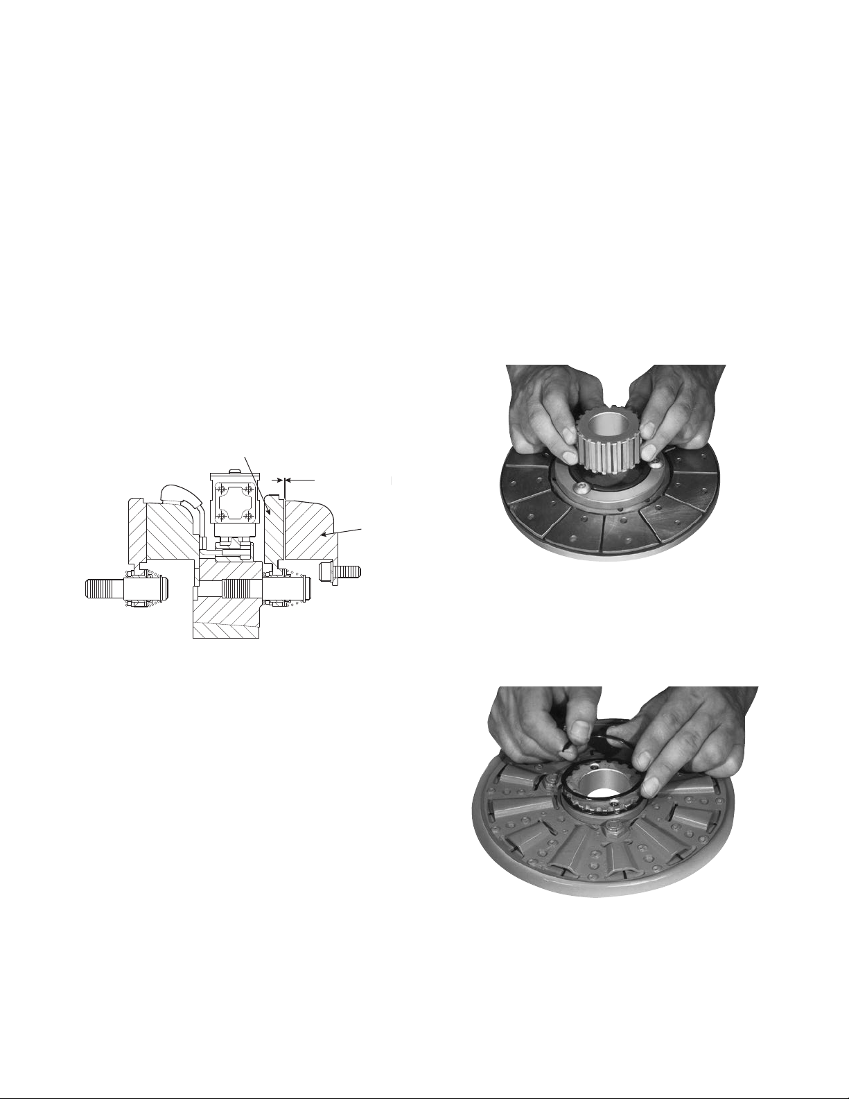
a. Place the armature-adapter assembly on a
flat surface with the segmented side up.
b. Push the splined hub, with the pilot diameter
down (refer to illustration drawings) through
the autogap spring and splined armature
adapter. (Figure 12)
Maintain a 1/16-inch clearance between the
armature adapter and the customer part after
the parts have been assembled.
G. Mounting the Clutch Armature Assembly
1. Slide the complete armature and customer
supplied pulley, sprocket or hub assembly on to
the shaft.
2. Adjust the armature's position to allow a 1/16inch gap between the magnet and armature
faces. (Figure 13)
Warner Electric • 800-234-3369 P- 205-01 • 819-0474
8
Figure 12
Figure 13
3. Secure the armature assembly in position by a)
retainer rings, b) set collars, c) shoulder on the
shaft, or d) any combination of these. The best
method will depend on the characteristics of
each application.
4. When the armature is secure on the shaft, push
the armature against the magnet face. When the
armature is released, it will spring back about
1/32-inch. This gap will be automatically
maintained for the life of the unit.
Page 9
H. Mounting the Brushholder
Field
Pilot diameter
Mounting Surface
1. The brushholder is mounted on a bracket which
must be furnished by the customer. The bracket
must be firmly secured to prevent vibration
which could cause improper contact between
the brushes and collector ring.
Clutch-Brake Coupling
PCBC-825 PCBC-1000 PCBC-1225
The illustration drawings, parts lists, and exploded
views for these units can be found beginning on
page 28.
The brake half of the clutch/brake unit is usually
installed first; however, in some cases it may be
necessary to start with the clutch portion of the
unit to assure a proper assembly when complete.
A. Installing the Conduit Box
Install the conduit box on the brake magnet.
Instructions for this procedure can be found with
Conduit Box.
2. The distance from the centerline of the shaft to
the top of the brushholder should be 5-3/4".
Maintaining this distance will assure proper
spring tension on the brushes and maximum
wear follow-up. A detailed dimensional drawing
is included with each brushholder.
Figure 1
2. A machined pilot diameter is provided on the
magnet mounting flange (refer to illustration
drawings) to aid in the proper positioning of the
magnet.
B. Mounting the Brake Magnet
The brake magnet is mounted to a stationary
machine member by a flange. Extreme care must
be taken in selecting the location for the mounting
of the magnet. Proper positioning is very
important for the unit to function correctly.
1. A pilot diameter on the mounting surface is
essential to hold the magnet within the
required tolerances. (Figure 1)
Warner Electric • 800-234-3369 P-205-01 • 819-0474
3. Once the mounting surface has been prepared,
the magnet is bolted in place with capscrews
and lockwashers. (Figure 2)
Figure 2
9
Page 10
4. Use a dial indicator to check the unit for con-
Short
Wire
Collector
Ring
Terminal
Cap
Long
Wire
Armature Boss
Straight Spring
(White)
Detent Spring
Retainer
Retainer
Ring
Detent
Spring
Drive Pin
Heavy
Spring
(Red)
Armature
centricity and squareness to the shaft. The unit
should be concentric within .010 T.I.R. and
square within .006 T.I.R. (Figure 3)
Figure 5
3. Secure the lead wires to the magnet terminals
with screws and lockwashers.
Figure 3
C. Assembling the Clutch Magnet and
Magnet Hub
1. Insert the lead wires through the rubber
terminal caps and onto the collector ring. The
shorter wire goes into the hole in the front of
the ring (the side that will be mounted to the
magnet). The longer wire goes through the ring
and into the hole in the back.
Press the bullet-type connectors firmly into
place. (Figure 4)
4. Pull the rubber caps over the terminals.
D. Assembling the Brake Armature and
Magnet Hub
Assemble the armature to the magnet hub with
the autogap mounting accessory.
The autogap assembly is a double spring device
which allows for automatic armature clearance
and adjustment for wear. The smaller or conical
spring pushes the armature from the magnet face,
leaving a gap of about 1/32 inch, while the
straight spring automatically follows up for wear.
This combination maintains maximum efficiency
throughout the life of the unit.
The assembly procedure for the autogap
accessory is as follows (Figure 6):
10
2. Mount the magnet to the magnet hub using
capscrews and lockwashers. (Figure 5)
Warner Electric • 800-234-3369 P- 205-01 • 819-0474
Figure 4
(Figure 6)
Page 11
Note: The 1225 unit is mounted with four drive
pins instead of three as shown in the pictures;
however, the assembly procedure is the same
for either case.
Step 1
Place straight springs (white) over armature
bosses on back side of armature. (Figure 7)
Figure 9
Step 4
Tighten pins until shoulders of pins are against
face of hub. Since threads are class No. 3 fit, pins
may seem to bind.
Figure 7
Step 2
Compress the heavy (red) spring on each drive pin
by sliding detent spring towards head of pin.
(Figure 8)
Figure 8
Step 3
Insert assembled drive pins through armature
(entering from segmented side), through straight
(white) springs, and into magnet hub.
Straight springs must not get
caught under shoulders of drive pins.
Step 5
Check to see that the armature is completely
compressed against the face of the hub.
Step 6
To set the autogap, slide the detent spring
retainers against the armature face.
Note: This position must not be disturbed
during completion of assembly. (Figure 10)
Note: Apply Grade "AA" Loctite® Sealant on
pin threads. (Figure 9)
Figure 10
Warner Electric • 800-234-3369 P-205-01 • 819-0474
11
Page 12
E. Mounting the Magnet-Hub-Armature
Armature
Brake
1/32-inch Gap
Assembly
This assembly is mounted on the shaft with a
taperlock bushing. All parts must be clean and
free from burrs and chips before assembling.
1. Place the bushing into the hub, and insert the
key. The key is a side-to-side fit and should not
contact the top of the keyway.
2. Insert the locking setscrews loosely into the
bushing, and slide the assembly onto the shaft.
3. Position the assembly to allow a gap of about
1/32-inch between the brake magnet and
armature faces. (Figure 11)
These units are shipped with the armature,
splined armature adapter, and autogap already
assembled. The splined hub, retainer ring, and
bushing are shipped as separate parts.
Follow these instructions to assemble the
armature and splined hub.
Step 1
Place the armature-splined adapter assembly on
a flat surface with the segmented side up. Push
the splined hub, with the retainer ring groove
down, through the autogap spring and splined
armature adapter. (Figure 12)
Figure 11
Once this gap is set, it will be automatically
maintained for the life of the unit.
4. Secure the assembly in this position on the
shaft by alternately tightening each setscrew.
During the tightening process the bushing
should be tapped lightly to make certain it
seats-in properly.
F. Assembling the Clutch Armature
The spline drive armatures are shipped with a
built-in autogap spring accessory. This device
automatically maintains a gap of about 1/32-inch
between the armature and magnet faces for the
life of the unit.
Figure 12
Step 2
Turn the armature-adapter assembly over, and
insert the retainer ring in the groove. (Figure 13)
Figure 13
Step 3
Slide the armature-adapter assembly up against
the retainer ring.
Warner Electric • 800-234-3369 P- 205-01 • 819-0474
12
Page 13
Step 4
Armature
1/32-inch Gap
Clutch
Magnet
Insert the bushing into the retainer ring side of the
splined hub. The clearance holes in the bushing
flange should line up with the tapped holes in the
splined hub. (Figure 14)
3. When the bushing is secure on the shaft,
push the armature against the magnet face.
When the armature is released, it will spring
back about 1/32". The gap will be
automatically maintained for the life of the
unit.
H. Mounting the Brushholder
1. The brushholder is mounted on a bracket
which must be furnished by the customer.
The bracket must be firmly secured to
prevent vibration which could cause improper
contact between the brushes and
collector ring.
Figure 14
G. Mounting the Armature and Hub
Assembly
1. Slide the complete armature and hub assembly
onto the shaft until the armature face touches
the magnet face.
2. Tighten the bushing capscrews, taking a few
turns at a time on each capscrew. As the
capscrews are tightened, the armature will
back away slightly from the magnet. There
should be a clearance of 1/16" between the
armature and magnet when the capscrews are
completely tight. (Figure 15)
2. The distance from the centerline of the shaft
to the top of the brushholder should be
5-3/4". Maintaining this distance will assure
proper spring tension on the brushes and
maximum wear follow-up. A detailed
dimensional drawing is included with each
brushholder.
Warner Electric • 800-234-3369 P-205-01 • 819-0474
Figure 15
13
Page 14

Coil Data
Unit Size PB & PC-825 PB & PC-1000 PB & PC-1225
Voltage — DC 6 24 90 6 24 90 6 24 90
Resistance @ 20°C — Ohms 1.27 20.4 223.3 1.23 19.7 248.7 1.33 22.2 61.7
Current — Amperes 4.74 1.18 .4 4.87 1.22 .36 4.5 1.08 .34
Watts 28 28 36 29 29 33 27 26 31
Coil Build-up — Milliseconds 170 170 170 205 220 235 300 320 350
Coil Decay — Milliseconds 70 75 80 70 75 80 190 190 190
Notes: Build-up time equals current to approximately* 90% of steady state value and flux to 90%.
Decay time equals current to approximately* 10% of steady state value and flux to 10%.
*Approximately because current leads or lags flux by a small amount.
Burnishing and Maintenance
Burnishing
Intimate metal to metal contact is essential
between the armature and the metal rings (poles)
of the magnet or rotor. Warner Electric clutches
and brakes leave the factory with the friction
material slightly undercut to assure good initial
contact.
Normally, the desired wearing-in process occurs
naturally as the surfaces slip upon engagement.
The time for wear-in, which is necessary to obtain
the ultimate torque of the unit, will vary depending
on speed, load, or cycle duty.
If maximum torque is required immediately after
installation, the unit should be burnished by
slipping the friction surfaces together at reduced
voltage. It is recommended that the burnishings
be done right on the application, if at all possible.
Burnishing at high speed will result in a smoother
wear-in pattern and reduce the time for burnishing.
The voltage should be set at approximately 30%
or 40% of the rated value.
The unit should be cycled on and off to allow
sufficient time between slip cycles to prevent
overheating.
When a Warner Electric brake or clutch is
properly assembled and installed, no further
servicing, lubrication, or maintenance should be
required throughout the life of the unit.
Maintenance
Wear Pattern: Wear grooves appear on the
armature and magnet surfaces. This is a normal
wear condition, and does not impair functioning of
the unit. Normally, the magnet and armature, as a
mating pair, will wear at the same rate. It is the
usual recommendation that both components be
replaced at the same time.
Remachining the face of a worn armature is not
recommended. If a replacement armature is to be
used with a used magnet, it is necessary to
remachine the worn magnet face. In refacing a
magnet: (1) machine only enough material to
clean up the complete face of the magnet; (2)
hold the face within .005" of parallel with the
mounting plate; and (3) undercut the molded
facing material .002" - .004" below the metal
poles.
Warner Electric • 800-234-3369 P- 205-01 • 819-0474
14
Page 15

Heat: Excessive heat and high operating
temperatures are causes of rapid wear. Units,
therefore, should be ventilated as efficiently as
possible, especially if the application requires fast,
repetitive cycle operation.
Foreign Materials: If units are used on machinery where fine, abrasive dust, chips or grit are
dispelled into the atmosphere, shielding of the
brake may be necessary if maximum life is to be
obtained.
Where units are used near gear boxes or
transmissions requiring frequent lubrication,
means should be provided to protect the friction
surfaces from oil and grease to prevent serious
loss of torque.
Oil and grease accidently reaching the friction
surfaces may be removed by wiping with a rag
dampened with a suitable cleaner, which leaves
no residue. In performing this operation, do not
drench the friction material.
If the friction materials have been saturated with
oil or grease, no amount of cleaning will be
completely effective. Once such a unit has been
placed back in service, heat will cause the oil to
boil to the surface, resulting in further torque loss.
6-Volt Series: Use a DC voltmeter of
approximately 0-15 volt range. A normal
reading is from 5.5 to 6.5 volts.
The above checks normally are sufficient. Further
checks may be made as follows: a low range
ammeter, when connected in series with one
magnet lead, will normally indicate approximately
.40 amperes for the 90 volt units, 1.0 ampere for
the 24 volt, and 3.5 amperes for the 6 volt series.
These readings are with the power on and the
potentiometer control in the maximum position.
Ohmmeter checks should be made with the
power off and the circuit open (to be certain,
disconnect one lead to the magnet). Average
resistance for the 90 volt series is 220 ohms; for
the 24 volt, 20 ohms; and for the 6 volt series, 1.5
ohms. A very high or infinite resistance reading
would indicate an open coil.
If the above checks indicate that the proper
voltage and current is being supplied to the
magnet, mechanical parts should be checked to
assure that they are in good operating condition
and properly installed.
Torque Loss: If a brake or clutch slips or loses
torque completely, the initial check should be the
input voltage to the magnet as follows:
90-Volt Series: Connect a DC voltmeter with a
range of 0-100 or more directly across the
magnet terminals. With the power on and the
potentiometer turned up, a normal reading is 90
volts, although 85 to 95 is satisfactory. The
reading should drop as the potentiometer control
is adjusted counterclockwise.
24-Volt Series: Use a DC voltmeter with a range
of 0-30 volts or more. A normal reading is
approximately 22-26 volts.
Warner Electric • 800-234-3369 P-205-01 • 819-0474
15
Page 16

PCB-825 Clutch-Brake Normal Duty Drawing I-25568
See page 34 for details on
Bore & Keyway.
Armature View
3.750
See page 6 for details for
drive pin mountings.
Removable plug in ends for
1/2" conduit.
9.437
Max.
8.625
Dia.
3.5625
Dia.
2.562
Dia.
1.500
1.593
2.718
2.562 Dia.
1.546
Max.
.921
.171
5/16-18
UNC-3A
5.656
5.750
.562
.358/.338 dia. (6) holes
equally spaced on
4.250 dia.*
6.812 Max.
3.503/3.502 Pilot
Dia.
.358/.338 dia. (4)
holes equally spaced
on 8.875 dia.*
9.749/9.747 Pilot Dia.
Magnet View
Customer Shall Maintain:
1. Concentricity of brake mounting pilot diameter
with mounting shaft within .010 T.I.R.
2. Squareness of brake magnet mounting face
with mounting shaft within .006 T.I.R. measured
at magnet mounting bolt circle.
.562
.093 When New
1.312
.562
5.468 Max.
1.312 Max.
.093
When New
* Mounting holes are within .010 of true position
relative to pilot diameter.
Shaft Size .500 – 1.625
Static Torque 125 lb. ft.
Maximum Speed 4,000 rpm
Standard Voltage D.C. 6, 24, 90
All dimensions are nominal unless otherwise noted.
Warner Electric • 800-234-3369 P-205-01 • 819-0474
16
Page 17

PCB-825 Clutch Brake Flange Mounted Per I-25568 Inside Mtd. Outside Mtd.
7
4-1
4
3
2
1
6-1
6
5-2
8
5-1
5 (Shipped Assembled)
9
10A
11A
11A-1
12
12
11B
11B-1
10B
PCB-825, N.D.
Item Description Part Number Qty.
1 Armature 5301-111-018 1
2 Autogap Accessory 5201-101-008 3
3 Mounting Accessory 5321-101-001 1
4 Magnet 1
6 Volt 5301-631-002
24 Volt 5301-631-004
90 Volt 5301-631-005
4-1 Terminal Accessory 5311-101-001 1
5 Magnet Hub 1
5-1 Collector Ring 5301-749-001 1
5-2 Collector Ring Assembly 5301-101-002 1
6 Brushholder 5300-178-001 1
6-1 Brush 176-0001 4
7 Bushing*
8 Armature 5301-111-018 1
9 Autogap Accessory 5201-101-008 3
10A Mounting Accessory - I.M. 5321-101-001 1
10B Mounting Accessory - O.M. 5321-101-002 1
11A Magnet - Inside Mounted 1
11A-1 Terminal Accessory 5311-101-001 1
11B Magnet - Outside Mounted 1
Left Hand 5301-541-001
Right Hand 5301-541-002
1/2" to 1-5/8"Bore 180-0131 to 180-0149 1
6 Volt 5311-631-002
24 Volt 5311-631-003
90 Volt 5311-631-004
6 Volt 5311-631-007
Item Description Part Number Qty.
24 Volt 5311-631-009
90 Volt 5311-631-008
11B-1 Terminal Accessory 5311-101-001 1
12 Conduit Box 5200-101-011 1
*See page 34 for specific part numbers
How to Order:
1. Specify Voltage for Item 4 and Item 11A or 11B.
2. Specify left hand or right hand hub for Item 5.
Bushing enters from magnet side for L.H. hub and
from hub side for R.H.
3. Specify Bore Size for Item 7.
4. Specify Inside Mounted for Items 10A and 11A or
Outside Mounted for Items 10B and 11B.
Example:
PCB-825 Clutch Brake per I-25568 - 90 Volt, Left
Hand hub, 1" Bore, Inside Mounted
These units meet standards set forth in UL508 and
are listed under guide card #NMTR2, file #59164.
These units are CSA certified under file #LR11543.
PCB-825, N.D.
Warner Electric • 800-234-3369 P-205-01 • 819-0474
17
Page 18

PCB-1000 Clutch-Brake Normal Duty Drawing I-25588
See page 34 for details
on Bore & Keyway.
2.906
1.546
Max.
.921
.171
5/16-18
UNC-3A
6.531
5.750
7.687 Max.
Armature View
3.750
See page 6 for details on
drive pin mountings.
Removable plug in ends
for 1/2" conduit.
.358/.338 dia. (6) holes
equally spaced on
6.125 dia.*
5.378/5.376
Pilot Dia.
.358/.338 dia. (8) holes
equally spaced on
10.625 dia.*
11.500/11.498
Pilot Dia.
11.093
Max.
10.296
Dia.
5.252
Dia.
.093 When New
4.125
Dia.
.562
1.453
1.750
1.906
.562
6.031 Max.
.562
4.125 Dia.
1.453 Max.
.093
When New
* Mounting holes are within .010 of true position
relative to pilot diameter.
Magnet View
(Inside & Outside Mounted)
Shaft Size .500 – 2.500
Static Torque 240 lb. ft.
Customer Shall Maintain:
1. Concentricity of brake mounting pilot diameter
Maximum Speed 3,600 rpm
Standard Voltage D.C. 6, 24, 90
with mounting shaft within .010 T.I.R.
2. Squareness of brake magnet mounting face
with mounting shaft within .006 T.I.R. measured
All dimensions are nominal unless otherwise noted.
at magnet mounting bolt circle.
Warner Electric • 800-234-3369 P-205-01 • 819-0474
18
Page 19

7
4-1
4
3
2
1
6-1
6
5-2
8
5-1
5 (Shipped Assembled)
9
10A
11A
11A-1
12
12
11B
11B-1
10B
PCB-1000 Clutch Brake Flange Mounted Per I-25588 Inside Mtd. Outside Mtd.
PCB-1000, N.D.
Item Description Part Number Qty.
1 Armature 5302-111-013 1
2 Autogap Accessory 5201-101-008 3
3 Mounting Accessory 5321-101-001 1
4 Magnet 1
6 Volt 5302-631-003
24 Volt 5302-631-014
90 Volt 5302-631-005
4-1 Terminal Accessory 5311-101-001 1
5 Magnet Hub 1
5-1 Collector Ring 5301-749-001 1
5-2 Collector Ring Assembly 5302-101-002 1
6 Brushholder 5300-178-001 1
6-1 Brush 176-0001 4
7 Bushing*
8 Armature 5302-111-013 1
9 Autogap Accessory 5201-101-008 3
10A Mounting Accessory - I.M. 5321-101-001 1
10B Mounting Accessory - O.M. 5321-101-002 2
11A Magnet - Inside Mounted 1
11A-1 Terminal Accessory 5311-101-001 1
11B Magnet - Outside Mounted 1
Left Hand 5302-541-001
Right Hand 5302-541-002
1/2" to 2-1/2" Bore 180-0185 to 180-0217 1
6 Volt 5312-631-004
24 Volt 5312-631-005
90 Volt 5312-631-006
6 Volt 5312-631-011
Item Description Part Number Qty.
24 Volt 5312-631-013
90 Volt 5312-631-012
11B-1 Terminal Accessory 5311-101-001 1
12 Conduit Box 5200-101-011 1
*See page 34 for specific part numbers.
How to Order:
1. Specify Voltage for Item 4 and Item 11A or 11B.
2. Specify left hand or right hand hub for Item 5.
Bushing enters from magnet side for L.H. hub and
from hub side for R.H.
3. Specify Bore Size for Item 7.
4. Specify Inside Mounted for Items 10A and 11A or
Outside Mounted for Items 10B and 11B.
Example:
PCB-1000 Clutch Brake per I-25588 - 90 Volt, Left
Hand hub, 1-1/2" Bore, Inside Mounted
These units meet standards set forth in UL508 and
are listed under guide card #NMTR2, file #59164.
These units are CSA certified under file #LR11543.
PCB-1000, N.D.
Warner Electric • 800-234-3369 P-205-01 • 819-0474
19
Page 20

PCB-1225 Clutch-Brake Normal Duty Drawing I-25608
See page 34 for details
on Bore & Keyway.
3.250
1.546
.921
.171
Max.
5/16-18 UNC-3A
7.531
5.750
8.687
See page 6 for details on
Drive Pin mountings.
Armature View
3.750
Removable plug in ends
for 1/2" conduit.
.358/.338 dia. (6) holes equally
spaced on 7.250 dia.*
6.378/6.376
Pilot Dia.
13.140
Max.
5.877
Dia.
12.625
Dia.
.093 When New
4.625
Dia.
.593
1.640
3.000
3.156
.093
When
New
.593
6.906 Max.
4.625 Dia.
.562
Max.
1.640
* Mounting holes are within .010 of true position
relative to pilot diameter.
Magnet View
13.875/13.871
Pilot Dia.
.358/.338 dia. (8) holes
equally spaced on 13.000
dia.
(Inside & Outside Mounted)
Shaft Size .937 – 3.000
Static Torque 465 lb. ft.
Customer Shall Maintain:
1. Concentricity of brake mounting pilot diameter
Maximum Speed 3,000 rpm
Standard Voltage D.C. 6, 24, 90
with mounting shaft within .010 T.I.R.
2. Squareness of brake magnet mounting face
with mounting shaft within .006 T.I.R measured
All dimensions are nominal unless otherwise noted.
at magnet mounting bolt circle.
Warner Electric • 800-234-3369 P-205-01 • 819-0474
20
Page 21

6-1
6
8
5-1
5-2
9
11A
11A-1
11B
12
13
11B-1
10B
2
1
3
4
4-1
7
10A
5
(Shipped
Assembled)
PCB-1225 Clutch Brake Flange Mounted Per I-25608 Inside Mtd. Outside Mtd.
PCB-1225 N.D.
Item Description Part Number Qty.
1 Armature 5303-111-009 1
2 Autogap Accessory 5201-101-008 4
3 Mounting Accessory 5321-101-001 1
4 Magnet 1
6 Volt 5303-631-005
24 Volt 5303-631-007
90 Volt 5303-631-008
4-1 Terminal Accessory 5311-101-001 1
5 Magnet Hub 1
Left Hand 5303-541-001
Right Hand 5303-541-002
5-1 Collector Ring 5301-749-001 1
5-2 Collector Ring Assembly 5303-101-004 1
6 Brushholder 5300-178-001 1
6-1 Brush 176-0001 4
7 Bushing*
15/16" to 3" Bore 180-0262 to180-0295 1
8 Armature 5303-111-009 1
9 Autogap Accessory 5201-101-008 4
10A Mounting Accessory - I.M. 5321-101-001 1
10B Mounting Accessory - O.M. 5321-101-002 2
11A Magnet - Inside Mounted 1
6 Volt 5313-631-005
24 Volt 5313-631-006
90 Volt 5313-631-007
11A-1 Terminal Accessory 5311-101-001 1
11B Magnet - Outside Mounted 1
6 Volt 5313-631-010
Item Description Part Number Qty.
24 Volt 5313-631-012
90 Volt 5313-631-011
11B-1 Terminal Accessory 5311-101-001 1
12 Conduit Box 5200-101-011 1
*See page 34 for specific part numbers.
How to Order:
1. Specify Voltage for Item 4 and Item 11A or 11B.
2. Specify left hand or right hand hub for Item 5.
Bushing enters from magnet side for L.H. hub
and from hub side for R.H.
3. Specify Bore Size for Item 7.
4. Specify Inside Mounted for Items 10A and 11A or
Outside Mounted for Items 10B and 11B.
Example:
PCB-1225 Clutch Brake per I-25608 - 90 Volt, Left
hand hub, 2" Bore, Inside Mounted.
These units meet the standards of UL508 and are
listed under guide card #NMTR2, file #59164. These
units are CSA certified under file #LR11543.
PCB-1225 N.D.
Warner Electric • 800-234-3369 P-205-01 • 819-0474
21
Page 22
PCB-825 Clutch-Brake Heavy Duty Drawing I-25569
.271/.263 dia. (5) holes (hub) equally spaced
on 2.015 dia. and within .003 of true position
in relation to 2.313/2.311 pilot dia.
2.178
1.546
.921
.171
Max.
5.656
5.750
.562
Max.
Armature View
1.640 Dia. Bore
Max. Length of
Customer Pilot
9.437
8.625
Running
Dia.
Dia.
.093
2.313
2.311
Pilot
Dia.
1.343
1/4-28
UNF-3A
1.500
1.593
5/16-18
UNC-3A
2.562
Dia.
3.750
6.812
See page 34 for
details on
Bushings.
Removable plug in ends for
1/2" conduit.
.358/.338 dia. (6)
holes equally spaced
on 4.250 dia.*
3.503/3.501
Pilot Dia.
.358/.338 dia. (4)
holes equally
spaced on 8.875
dia.
9.749/9.747 Pilot Dia.
Magnet View
(Inside & Outside Mounted)
Customer Shall Maintain:
1. Concentricity of brake magnet mounting pilot
diameter with mounting shaft within .010 T.I.R.
2. Squareness of brake magnet mounting face
with magnet mounting shaft within .006 T.I.R.
3. Splined hub pilot diameter to be concentric
with splined armature center of rotation within
.010 T.I.R.
4. Mounting shaft to be concentric with splined
armature center of rotation within .006 T.I.R.
.062
.531
.468 Max.
.125
1.312
5.640 Max.
.562
1.437
1.312
.093 When New
* Mounting holes are within .010 of true position
relative to pilot diameter.
Shaft Size .500 – 1.625
Static Torque 125 lb. ft.
Maximum Speed 4,000 rpm
Standard Voltage D.C. 6, 24, 90
All dimensions are nominal unless otherwise noted.
Warner Electric • 800-234-3369 P-205-01 • 819-0474
22
Page 23

3
(Shipped
Assembled)
5
5-1
8
4
3-5
3-2
3-1
3-6
1
2
3-3
3-4
13A
9
9-1
10
7-1
7
6
11
12A
12B
13B-1
14
13B
13A-1
14
PCB-825 Clutch Brake Flange Mounted Per I-25569 Inside Mtd. Outside Mtd.
PCB-825 H.D.
Item Description Part Number Qty.
1 Splined Hub 540-0146 1
2 Mounting Accessory 5201-101-001 1
3 Armature Accessory 5321-111-001 1
3-1 Armature 5321-111-022 1
3-2 Armature Adapter 104-0008 1
3-3 Autogap Spring 808-0054 1
3-4 Retainer Ring 748-0373 1
3-5 Buttonhead Screw 797-0272 3
3-6 Locknut 661-0004 3
4 Mounting Accessory 5321-101-001 1
5 Magnet 1
6 Volt 5301-631-002
24 Volt 5301-631-004
90 Volt 5301-631-005
5-1 Terminal Accessory 5311-101-001 1
6 Magnet Hub 1
Right Hand 5301-541-002
Left Hand 5301-541-001
7 Collector Ring 5301-749-001 1
7-1 Collector Ring Accessory 5301-101-002 1
8 Bushing* 180-0131 to 180-0149 1
9 Brushholder 5300-178-001 1
9-1 Brush 176-0001 4
10 Armature 5301-111-018 1
11 Autogap Accessory 5201-101-008 3
12A Mounting Accessory - I.M. 5321-101-001 1
12B Mounting Accessory - O.M. 5321-101-002 1
13A Magnet - Inside Mounted 1
Warner Electric • 800-234-3369 P-205-01 • 819-0474
6 Volt 5311-631-002
24 Volt 5311-631-003
90 Volt 5311-631-004
Item Description Part Number Qty.
13A-1 Terminal Accessory 5311-101-001 1
13B Magnet Hub - Outside Mounted 1
6 Volt 5311-631-007
24 Volt 5311-631-009
90 Volt 5311-631-008
13B-1 Terminal Accessory 5311-101-001 1
14 Conduit Box 5200-101-011 1
*See page 34 for specific part numbers.
How to Order:
1. Specify Voltage for Item 5 and Item 13A or 13B.
2. Specify left hand or right hand hub for Item 6.
Bushing enters from magnet side for L.H. hub
and from hub side for R.H. hub.
3. Specify Bore Size for Item 8.
4. Specify Inside Mounted for Items 12A and 13A
or Outside Mounted for Item 12B and 13B.
Example:
PCB-825 Clutch Brake per I-25569 - 90 Volt, Left
Hand hub, 1" Bore, Inside Mounted.
These units meet the standards of UL508 and are
listed under guide card #NMTR2, file #59164. These
units are CSA certified under file #LR11543.
PCB-825 H.D.
23
Page 24

PCB-1000 Clutch-Brake Heavy Duty Drawing I-25589
.397/.388 dia. (3) holes (hub) equally spaced on
3.187 dia. and within .003 of true position in rela-
7.687
tion to 4.001/3.999 pilot dia.
Armature View
3.750
2.562 Dia. Bore
Removable plug in ends
for 1/2" conduit.
.358/.338 dia. (6)
holes equally spaced
on 6.125 dia.*
5.378/5.376
Pilot Dia.
Max. Length of
Customer Pilot
11.093
10.296
Running
Dia.
Dia.
.843 Max.
.062
.093
4.001
3.999
Pilot
Dia.
.500
1.375
3/8-16
UNF-2A
1.453
.125
6.218 Max.
1.750
1.906
.562
1.750
2.906
1.546
4.125
Dia.
1.456
.093 When New
.921
.171
Max.
5/16-18
UNC-3A
6.531
5.750
.562
Max.
See page 34 for
details on
Bushings.
.358/.338 dia. (8)
holes equally
spaced on 10.625
dia.
11.500/11.498 Pilot Dia.
* Mounting holes are within .010 of true position
relative to pilot diameter.
Magnet View
(Inside & Outside Mounted)
Customer Shall Maintain:
1. Concentricity of brake magnet mounting pilot
diameter with mounting shaft within .010 T.I.R.
2. Squareness of brake magnet mounting face with
Shaft Size .500 – 2.500
Static Torque 240 lb. ft.
Maximum Speed 3,600 rpm
Standard Voltage D.C. 6, 24, 90
magnet mounting shaft within .006 T.I.R.
3. Splined hub pilot diameter to be concentric with
splined armature center of rotation within .010
All dimensions are nominal unless otherwise noted.
T.I.R.
4. Mounting shaft to be concentric with splined
armature center of rotation within .006 T.I.R.
Warner Electric • 800-234-3369 P-205-01 • 819-0474
24
Page 25

3
(Shipped
Assembled)
5
5-1
8
4
3-5
3-2
3-1
3-6
1
2
3-3
3-4
13A
9
9-1
10
7-1
7
6
11
12A
12B
13B-1
14
13B
13A-1
14
PCB-1000 Clutch-Brake Flange Mounted Per I-25589 Inside Mtd. Outside Mtd.
PCB-1000 H.D.
Item Description Part Number Qty.
1 Splined Hub 540-0147 1
2 Mounting Accessory 5202-101-001 1
3 Armature Accessory 5322-111-002 1
3-1 Armature 5322-111-036 1
3-2 Armature Adapter 104-0009 1
3-3 Autogap Spring 808-0061 1
3-4 Retainer Ring 748-0374 1
3-5 Buttonhead Screw 797-0272 3
3-6 Locknut 661-0004 3
4 Mounting Accessory 5321-101-001 1
5 Magnet 1
6 Volt 5302-631-003
24 Volt 5302-631-014
90 Volt 5302-631-005
5-1 Terminal Accessory 5311-101-001 1
6 Magnet Hub 1
Right Hand 5302-541-002
Left Hand 5302-541-001
7 Collector Ring 5301-749-001 1
7-1 Collector Ring Accessory 5301-101-002 1
8 Bushing* 180-0185 to 180-0217 1
9 Brushholder 5300-178-001 1
9-1 Brush 176-0001 4
10 Armature 5302-111-013 1
11 Autogap Accessory 5201-101-008 3
12A Mounting Accessory - I.M. 5321-101-001 1
12B Mounting Accessory - O.M. 5321-101-002 2
13A Magnet - Inside Mounted 1
Warner Electric • 800-234-3369 P-205-01 • 819-0474
6 Volt 5312-631-004
24 Volt 5312-631-005
Item Description Part Number Qty.
90 Volt 5312-631-006
13A-1 Terminal Accessory 5311-101-001 1
13B Magnet Hub - Outside Mounted 1
6 Volt 5312-631-011
24 Volt 5312-631-013
90 Volt 5312-631-012
13B-1 Terminal Accessory 5311-101-001 1
14 Conduit Box 5200-101-011 1
*See page 34 for specific part numbers.
How to Order:
1. Specify Voltage for Item 5 and Item 13A or 13B.
2. Specify left hand or right hand hub for Item 6.
Bushing enters from magnet side for L.H. hub
and from hub side for R.H. hub.
3. Specify Bore Size for Item 8.
4. Specify Inside Mounted for Items 12A and 13A or
Outside Mounted for Item 12B and 13B.
Example:
PCB-1000 Clutch Brake per I-25589 - 90 Volt, Left
Hand hub, 1-1/2" Bore, Inside Mounted
These units meet the standards of UL508 and are
listed under guide card #NMTR2, file #59164. These
units are CSA certified under file #LR11543.
PCB-1000 H.D.
25
Page 26

PCB-1225 Clutch-Brake Heavy Duty Drawing I-25609
(.397/.388) dia. (8) holes (hub) equally spaced on (3.625)
dia. and within .003 of true position in relative to
(4.313/4.311) pilot dia.
3.250
1.546
.921
8.687
Armature View
3.750
3.062 Dia. Bore
Removable plug in ends
for 1/2" conduit.
.358/.338 dia. (6) holes equally
spaced on 7.250 dia.*
6.378/6.376 Pilot Dia.
13.140
Running
Dia.
Length of
Customer
12.625
Dia.
.718 Max.
.093
Max.
Pilot
3/8-16
UNC-2A
4.313
4.311
Pilot Dia.
.125
.062
.562
1.500
When New
1.640
7.218 Max.
3
3.156
2.187
.093
.593
4.625 Dia.
1.640
.171
7.531
5.750
5/16-18
UNC-3A
.562
Max.
* Mounting holes are within .010 of true position
relative to pilot diameter.
See page 34
for details on
Bushings.
.358/.338 dia. (8) holes
equally spaced on
13.000 dia.
13.875/13.871 Pilot Dia.
Magnet View
(Inside & Outside Mounted)
Customer Shall Maintain:
1. Concentricity of brake magnet mounting pilot
diameter with mounting shaft within .010 T.I.R.
2. Squareness of brake magnet mounting face with
Shaft Size .937 – 3.000
Static Torque 465 lb. ft.
Maximum Speed 3,000 rpm
Standard Voltage D.C. 6, 24, 90
magnet mounting shaft within .006 T.I.R.
3. Splined hub pilot diameter to be concentric with
splined armature center of rotation within .010
All dimensions are nominal unless otherwise noted.
T.I.R.
4. Mounting shaft to be concentric with splined
armature center of rotation within .006 T.I.R.
Warner Electric • 800-234-3369 P-205-01 • 819-0474
26
Page 27

3
(Shipped
Assembled)
1
2
3-6
3-1
3-2
3-5
3-3
3-4
4
5
5-1
7
12A
11A
13
12A-1
12B
13
12B-
11B
4
10
9
8
8-1
6
6-1
6-2
PCB-1225 Clutch-Brake Flange Mounted Per I-25609 Inside Mtd. Outside Mtd.
PCB-1225 H.D.
Item Description Part Number Qty.
1 Splined Hub 540-0148 1
2 Mounting Accessory 5202-101-001 3
3 Armature Assembly 5323-111-001 1
3-1 Armature 5323-111-034 1
3-2 Armature Adapter 104-0010 1
3-3 Autogap Spring 808-0044 1
3-4 Retainer Ring 748-0370 1
3-5 Buttonhead Screw 797-0281 4
3-6 Locknut 661-0005 4
4 Mounting Accessory 5321-101-001 1
5 Magnet 1
6 Volt 5303-631-005
24 Volt 5303-631-007
90 Volt 5303-631-008
5-1 Terminal Accessory 5311-101-001 1
6 Magnet Hub 1
Right Hand 5303-541-002
Left Hand 5303-541-001
6-1 Collector Ring 5301-749-001 1
6-2 Collector Ring Accessory 5301-101-004 1
7 Bushing* 180-0262 to 180-0295 1
8 Brushholder 5300-178-001 1
8-1 Brush 176-0001 4
9 Armature 5303-111-009 1
10 Autogap Accessory 5201-101-008 4
11A Mounting Accessory
Inside Mounted 5321-101-001 1
11B Mounting Accessory
Outside Mounted 5321-101-002 2
12A Magnet - Inside Mounted 1
6 Volt 5313-631-005
Warner Electric • 800-234-3369 P-205-01 • 819-0474
Item Description Part Number Qty.
24 Volt 5313-631-006
90 Volt 5313-631-007
12A-1 Terminal Accessory 5311-101-001
12B Magnet - Outside Mounted 1
6 Volt 5313-631-010
24 Volt 5313-631-012
90 Volt 5313-631-011
12B-1 Terminal Accessory 5311-101-001 1
13 Conduit Box 5200-101-011 1
*See page 34 for specific part numbers.
How to Order:
1. Specify Voltage for Item 5 and Item 12A or 12B.
2. Specify left hand or right hand hub for Item 6.
Bushing enters from magnet side for L.H. hub and
from hub side for R.H.
3. Specify Bore Size for Item 7.
4. Specify Inside Mounted for Items 11A and 12A or
Outside Mounted for Items 11B and 12B.
Example:
PCB-1225 Clutch Brake per I-25609 - 90 Volt, Left
Hand hub, 2" Bore, Inside Mounted
These units meet the standards of UL508 and are
listed under guide card #NMTR2, file #59164. These
units are CSA certified under file #LR11543.
PCB-1225 H.D.
27
Page 28

PCBC-825 Clutch-Brake Coupling Drawing I-25570
2.718
1.546
.921
.171
Max.
5/16-18
UNC-3A
5.656
5.750
See page 34 for details
Armature View
on Bore & Keyway.
9.437
8.625
2.500
.156
1.250
1.765
1.500
1.593
.562
2.562 Dia.
3.750
6.812
See page 34 for
details on Bore &
Keyway.
Removable plug in ends
for 1/2" conduit.
.358/.338 dia. (6)
holes equally spaced
on 4.250 dia.*
3.503/3.501
Pilot Dia.
9.749/9.747
Pilot Dia.
.358/.338 dia. (4) holes
equally spaced on
8.875 dia.*
Magnet View
(Inside & Outside Mounted)
Customer Shall Maintain:
1. Armature mounting shaft concentric with magnet mounting shaft within .006 T.I.R.
2. Squareness of brake magnet mounting face
with magnet mounting shaft within .006 T.I.R.
3. Concentricity of brake magnet mounting pilot
diameter with magnet mounting shaft within
.010 T.I.R.
.062
.531
1.312
6.250 Max.
1.437
.562
1.312
.093 When New
* Mounting holes are within .010 of true position
relative to pilot diameter.
Armature Shaft .500 – 1.500
Magnet Shaft .500 – 1.625
Static Torque 125 lb. ft.
Maximum Speed 4,000 rpm
Standard Voltage D.C. 6, 24, 90
All dimensions are nominal unless otherwise noted.
Warner Electric • 800-234-3369 P-205-01 • 819-0474
28
Page 29

1
2
3
4-1
4-2
4-3
4-5
4
5
6
6-1
9
4-4
7-1
7-2
7
(Shipped Assembled)
11
8-1
8
10
12A
13A
13A-1
14
14
13B
13B-1
12B
PCBC-825 Clutch-Brake Coupling Per I-25570 Inside Mtd. Outside Mtd.
PCBC-825
Item Description Part Number Qty.
1 Bushing*
1/2" to 1-1/2" Bore 180-0002 to 180-0018 1
2 Retainer Ring 748-0006 1
3 Splined Hub 540-0057 1
4 Armature & Splined Adapter 5321-111-001 1
4-1 Locknut 661-0004 3
4-2 Armature 5321-111-022 1
Item Description Part Number Qty.
13B Magnet - Outside Mounted 1
6 Volt 5311-631-007
24 Volt 5311-631-009
90 Volt 5311-631-008
13B-1 Terminal Accessory 5311-101-001 1
14 Conduit Box 5200-101-011 1
*See page 34 for specific part numbers.
PCBC-825
4-3 Splined Adapter 104-0008 1
4-4 Autogap Accessory 5321-101-006 1
4-5 Screw 797-0272 3
5 Mounting Accessory 5321-101-001 1
6 Magnet 1
6 Volt 5301-631-002
24 Volt 5301-631-004
90 Volt 5301-631-005
6-1 Terminal Accessory 5311-101-001 1
7 Magnet Hub 1
Left Hand 5301-541-001
Right Hand 5301-541-002
7-1 Collector Ring 5301-749-001 1
7-2 Collector Ring Accessory 5301-101-002 1
8 Brushholder 5300-178-001 1
8-1 Brush 176-0001 4
9 Bushing*
10 Armature 5301-111-018 1
1/2" to 1-5/8" Bore 180-0131 to 180-0149 1
11 Autogap Accessory 5201-101-008 3
12A Mounting Accessory - I.M. 5321-101-001 1
12B Mounting Accessory - O.M. 5321-101-002 1
13A Magnet - Inside Mounted 1
6 Volt 5311-631-002
24 Volt 5311-631-003
90 Volt 5311-631-004
13A-1 Terminal Accessory 5311-101-001 1
Warner Electric • 800-234-3369 P-205-01 • 819-0474
How to Order:
1. Specify Bore Size for Items 1 and 9.
2. Specify Voltage for Items 6 and 13.
3. Specify left hand or right hand hub for Item 7.
Bushing enters from magnet side for L.H. hub
and from hub side for R.H.
4. Specify Inside Mounted for Items 12A and 13A or
Outside Mounted for Items 12B and 13B.
Example:
PCBC-825 Clutch Brake Coupling per I-25570 - 90
Volt, Inside Mounted, Left Hand hub, 1" Bore,
(Items 1 and 9)
These units meet the standards of UL508 and are
listed under guide card #NMTR2, file #59164. These
units are CSA certified under file #LR11543.
29
Page 30

PCBC-1000 Clutch-Brake Coupling Drawing I-25590
2.906
1.546
.921
.171
Max.
5/16-18
UNC-3A
6.531
See page 34 for details on
Bore & Keyway.
5.750
7.687
See page 34 for
details on Bore &
Keyway.
(Inside & Outside Mounted)
Armature View
3.750
Magnet View
Removable plug in ends
for 1/2" conduit.
.358/.338 dia. (6)
holes equally spaced
on 6.125 dia.*
5.378/5.376
Pilot Dia.
11.500/11.498
Pilot Dia.
.358/.338 dia. (8)
holes equally spaced
on 10.625 dia.*
11.093
10.296
4.093
.234
.062
.500
2.500
2.687
1.453
7.843 Max.
1.750
1.906
1.750
.562
.562
4.125 Dia.
1.453
.093 When New
* Mounting holes are within .010 of true position
relative to pilot diameter.
Armature Shaft .750 – 2.687
Customer Shall Maintain:
1. Armature mounting shaft concentric with
magnet mounting shaft within .006 T.I.R.
2. Squareness of brake magnet mounting face
with magnet mounting shaft within .006 T.I.R.
Magnet Shaft .500 – 2.500
Static Torque 240 lb. ft.
Maximum Speed 3,600 rpm
Standard Voltage D.C. 6, 24, 90
3. Concentricity of brake magnet mounting pilot
diameter with magnet mounting shaft within
.010 T.I.R.
Warner Electric • 800-234-3369 P-205-01 • 819-0474
30
All dimensions are nominal unless otherwise noted.
Page 31

1
2
3
4-1
4-2
4-3
4-5
4
5
6
6-1
9
4-4
7-1
7-2
7
(Shipped Assembled)
11
8-1
8
10
12A
13A
13A-1
14
14
13B
13B-1
12B
PCBC -1000 Clutch-Brake Coupling Per I-25590 Inside Mtd. Outside Mtd.
PCBC-1000
Item Description Part Number Qty.
1 Bushing*
3/4" to 2-11/16" Bore 180-0026 to 180-0057 1
2 Retainer Ring 748-0007 1
3 Splined Hub 540-0062 1
4 Armature & Splined Adapter 5322-111-002 1
4-1 Locknut 661-0004 3
4-2 Armature 5322-111-036 1
4-3 Splined Adapter 104-0009 1
4-4 Autogap Accessory 5322-101-004 1
Item Description Part Number Qty.
13A-1 Terminal Accessory 5311-101-001 1
13B Magnet - Outside Mounted 1
6 Volt 5312-631-011
24 Volt 5312-631-013
90 Volt 5312-631-012
13B-1 Terminal Accessory 5311-101-001 1
14 Conduit Box 5200-101-011 1
*See page 34 for specific part numbers.
PCBC-1000
4-5 Screw 797-0272 3
5 Mounting Accessory 5321-101-001 1
6 Magnet 1
6 Volt 5302-631-003
24 Volt 5302-631-014
90 Volt 5302-631-005
6-1 Terminal Accessory 5311-101-001 1
7 Magnet Hub 1
Left Hand 5302-541-001
Right Hand 5302-541-002
7-1 Collector Ring 5301-749-001 1
7-2 Collector Ring Accessory 5302-101-002 1
8 Brushholder 5300-178-001 1
8-1 Brush 176-0001 4
9 Bushing* 1
1/2" to 2-1/2" Bore 180-0185 to 180-0217
10 Armature 5302-111-013 1
11 Autogap Accessory 5201-101-008 3
12A Mounting Accessory - I.M. 5321-101-001 1
12B Mounting Accessory - O.M. 5321-101-002 2
13A Magnet - Inside Mounted 1
6 Volt 5312-631-004
24 Volt 5312-631-005
90 Volt 5312-631-006
Warner Electric • 800-234-3369 P-205-01 • 819-0474
How to Order:
1. Specify Bore Size for Items 1 and 9.
2. Specify Voltage for Items 6 and 13.
3. Specify left hand or right hand hub for Item 7.
Bushing enters from magnet side for L.H. hub
and from hub side for R.H.
4. Specify Inside Mounted for Items 12A and 13A or
Outside Mounted for Items 12B and 13B.
Example:
PCBC-1000 Clutch Brake Coupling per I-25590 - 90
Volt, Inside Mounted, Left Hand hub, 1-1/2" Bore,
(Items 1 and 9).
These units meet the standards of UL508 and are
listed under guide card #NMTR2, file #59164. These
units are CSA certified under file #LR11543.
31
Page 32

PCBC-1225 Clutch-Brake Coupling Drawing I-25612
3.250
1.546
.921
.171
5/16-18
UNC-3A
7.531
5.750
.562
4.625
Armature View
3.750
See page 34 for
details on Bore &
Keyway.
Removable plug in ends for
1/2" conduit.
13.140
12.625
4.093
.234
2.500
2.687
3.000
3.156
.358/.338 dia. (6) holes equally
8.687
See page 34 for details
on Bore & Keyway.
spaced on 7.250 dia.*
6.378/6.376 Pilot
Dia.
.358/.338 dia. (8) holes
equally spaced on
13.000 dia.*
13.875/13.871 Pilot Dia.
Magnet View
(Inside & Outside Mounted)
Customer Shall Maintain:
1. Armature mounting shaft concentric with
magnet mounting shaft within .006 T.I.R.
2. Squareness of brake magnet mounting face
with magnet mounting shaft within .006 T.I.R.
3. Concentricity of brake magnet mounting pilot
diameter with magnet mounting shaft within
.010 T.I.R.
1.640
8.718 Max.
2.187
.093
When
New
1.640
.593
.062
.562
*Mounting holes are within .010 of true position
relative to pilot diameter.
Armature Shaft .750 – 2.687
Magnet Shaft .937 – 3.000
Static Torque 465 lb. ft.
Maximum Speed 3,000 rpm
Standard Voltage D.C. 6, 24, 90
All dimensions are nominal unless otherwise noted.
Warner Electric • 800-234-3369 P-205-01 • 819-0474
32
Page 33

1
2
3
4-1
4-2
4-3
4-5
5
6
6-1
9
7
(Shipped
Assembled)
4
(Shipped
Assembled)
8-1
8
7-1
7-2
11
10
12A
13A
13A-1
14
14
13B-1
13B
12B
4-4
PCBC-1225 Clutch-Brake Coupling Per I-25612 Inside Mtd. Outside Mtd.
PCBC-1225
Item Description Part Number Qty.
1 Bushing*
3/4" to 2-11/16" Bore 180-0026 to 180-0056 1
2 Retainer Ring 748-0005 1
3 Splined hub 540-0064 1
4 Armature & Splined Adapter 5323-111-001 1
4-1 Locknut 661-0005 4
4-2 Armature 5323-111-034 1
4-3 Splined Adapter 104-0010 1
4-4 Autogap Accessory 5323-101-002 1
4-5 Screw 797-0281 4
5 Mounting Accessory 5321-101-001 1
6 Magnet 1
6 Volt 5303-631-005
24 Volt 5303-631-007
90 Volt 5303-631-008
6-1 Terminal Accessory 5311-101-001 1
7 Magnet Hub 1
Left Hand 5303-541-001
Right Hand 5303-541-002
7-1 Collector Ring 5301-749-001 1
7-2 Collector Ring Assembly 5303-101-004 1
8 Brushholder 5300-178-001 1
8-1 Brush 176-0001 4
9 Bushing*
15/16" to 3" Bore 180-0262 to 180-0295 1
10 Armature 5303-111-009 1
11 Autogap Accessory 5201-101-008 4
12A Mounting Accessory - I.M. 5321-101-001 1
12B Mounting Accessory - O.M. 5321-101-002 2
13A Magnet - Inside Mounted 1
6 Volt 5313-631-005
24 Volt 5313-631-006
Warner Electric • 800-234-3369 P-205-01 • 819-0474
Item Description Part Number Qty.
90 Volt 5313-631-007
13A-1 Terminal Accessory 5311-101-001 1
13B Magnet - Outside Mounted 1
6 Volt 5313-631-010
24 Volt 5313-631-012
90 Volt 5313-631-011
13B-1 Terminal Accessory 5311-101-001 1
14 Conduit Box 5200-101-011 1
*See page 34 for specific part numbers.
How to Order:
1. Specify Bore Size for Items 1 and 9.
2. Specify Voltage for Items 6 and 13.
3. Specify left hand or right hand hub for Item 7.
Bushing enters from magnet side for L.H. hub
and from hub side for R.H.
4. Specify Inside Mounted for Items 12A and 13A or
Outside Mounted for Items 12B and 13B.
Example:
PCBC-1225 Clutch Brake Coupling per I-25612 - 90
Volt, Inside Mounted Left Hand hub, 1-3/4" Bore
(Items 1 and 9).
These units meet the standards of UL508 and are
listed under guide card #NMTR2, file #59164. These
units are CSA certified under file #LR11543.
PCBC-1225
33
Page 34

Bushing Part Numbers
Browning Bushing
Dodge Bushing
Bushing Number
Shaft Size Keyway Size Warner Electric Browning
1/2 1/8 x 1/16 180-0002 H-1
9/16 1/8 x 1/16 180-0003
5/8 3/16 x 3/32 180-0004
11/16 3/16 x 3/32 180-0005
3/4 3/16 x 3/32 180-0006
13/16 3/16 x 3/32 180-0007
7/8 3/16 x 3/32 180-0008
15/16 1/4 x 1/8 180-0009
1 1/4 x 1/8 180-0010
1-1/6 1/4 x 1/8 180-0011
1-1/8 1/4 x 1/8 180-0012
1-3/16 1/4 x 1/8 180-0013
1-1/4 1/4 x 3/16 180-0014
1-5/16 5/16 x 7/32 180-0015
1-3/8 5/16 x 7/32 180-0016
1-7/16 3/8 x 1/4 180-0017 H-2
1-1/2 3/8 x 7/32 180-0018
3/4 1/2 x 3/8 180-0026 QI-1
13/16 1/2 x 3/8 180-0027
7/8 1/2 x 3/8 180-0028
15/16 1/2 x 3/8 180-0029
1 1/2 x 3/8 180-0030
1-1/16 1/2 x 3/8 180-0031
1-1/8 1/2 x 3/8 180-0032
1-3/16 1/2 x 3/8 180-0033
1-1/4 1/2 x 3/8 180-0034
1-5/16 1/2 x 3/8 180-0035
1-3/8 1/2 x 3/8 180-0036
1-7/16 1/2 x 3/8 180-0037
1-1/2 1/2 x 3/8 180-0038
1-9/16 1/2 x 3/8 180-0039
1-5/8 1/2 x 3/8 180-0040
1-11/16 1/2 x 3/8 180-0041
1-3/4 1/2 x 3/8 180-0042
1-13/16 1/2 x 3/8 180-0043
1-7/8 1/2 x 3/8 180-0044
1-15/16 1/2 x 3/8 180-0045
2 1/2 x 3/8 180-0046 QI-2
2-1/16 1/2 x 3/8 180-0047
2-1/8 1/2 x 3/4 180-0048
2-3/16 1/2 x 23/32 180-0049
2-1/4 1/2 x 11/16 180-0050
2-5/16 5/8 x 5/16 180-0051
2-3/8 5/8 x 5/16 180-0052
2-7/16 5/8 x 5/16 180-0053
2-1/2 5/8 x 5/16 180-0054
2-9/16 5/8 x 5/16 180-0055
2-5/8 5/8 x 5/16 180-0056
2-11/16 5/8 x 5/16 180-0057
Bushing Number
Shaft Size Keyway Size Warner Electric Dodge
1/2 1/8 x 1/16 180-0101 1210
9/16 1/8 x 1/16 180-0102
5/8 3/16 x 3/32 180-0103
11/16 3/16 x 3/32 180-0104
3/4 3/16 x 3/32 180-0105
13/16 3/16 x 3/32 180-0106
7/8 3/16 x 3/32 180-0107
5/16 1/4 x 1/8 180-0108
1 1/4 x 1/8 180-0109
1-1/16 1/4 x 1/8 180-0110
1-1/8 1/4 x 1/8 180-0111
1-3/16 1/4 x 1/8 180-0112
1-1/4 1/4 x 1/8 180-0113
1/2 1/8 x 1/16 180-0116 1215
9/16 1/8 x 1/16 180-0117
5/8 3/16 x 3/32 180-0118
11/16 3/16 x 3/32 180-0119
3/4 3/16 x 3/32 180-0120
13/16 3/16 x 3/32 180-0121
7/8 3/16 x 3/32 180-0122
15/16 1/4 x 1/8 180-0123
1 1/4 x 1/8 180-0124
1-1/16 1/4 x 1/8 180-0125
1-1/8 1/4 x 1/8 180-0126
1-3/16 1/4 x 1/8 180-0127
1-1/4 1/4 x 1/8 180-0128
1/2 1/8 x 1/16 180-0131 1615
9/16 1/8 x 1/16 180-0132
5/8 3/16 x 3/32 180-0133
11/16 3/16 x 3/32 180-0134
3/4 3/16 x 3/32 180-0135
13/16 3/16 x 3/32 180-0136
7/8 3/16 x 3/32 180-0137
15/16 1/4 x 1/8 180-0138
1 1/4 x 1/8 180-0139
1-1/16 1/4 x 1/8 180-0140
1-1/8 1/4 x 1/8 180-0141
1-3/16 1/4 x 1/8 180-0142
1-1/4 1/4 x 1/8 180-0143
1-5/16 5/16 x 5/32 180-0144
1-3/8 5/16 x 5/32 180-0145
1-7/16 3/8 x 3/16 180-0146
1-1/2 3/8 x 3/16 180-0147
1-9/16 3/8 x 3/16 180-0148
1-5/8 3/8 x 3/16 180-0149
1/2 1/8 x 1/16 180-0155 2012
9/16 1/8 x 1/16 180-0156
5/8 3/16 x 3/32 180-0157
11/16 3/16 x 3/32 180-0158
3/4 3/16 x 3/32 180-0159
13/16 3/16 x 3/32 180-0160
7/8 3/16 x 3/32 180-0161
15/16 1/4 x 1/8 180-0162
1 1/4 x 1/8 180-0163
1-1/16 1/4 x 1/8 180-0164
1-1/8 1/4 x 1/8 180-0165
1-3/16 1/4 x 1/8 180-0166
1-1/4 1/4 x 1/8 180-0167
Warner Electric • 800-234-3369 P-205-01 • 819-0474
34
Page 35

Bushing Part Numbers
Dodge Bushing
Bushing Number
Shaft Size Keyway Size Warner Electric Dodge
1-5/16 5/16 x 5/32 180-0168 2012
1-3/8 5/16 x 5/32 180-0169
1-7/16 3/8 x 3/16 180-0170
1-1/12 3/8 x 3/16 180-0171
1-9/16 3/8 x 3/16 180-0172
1-5/8 3/8 x 3/16 180-0173
1-11/16 3/8 x 3/16 180-0174
1-3/4 3/8 x 3/16 180-0175
1-13/16 1/2 x 1/4 180-0176
1-7/8 1/2 x 1/4 180-0177
1-15/16 1/2 x 1/4 180-0178
2 1/2 x 1/4 180-0179
1/2 1/8 x 1/16 180-0185 2517
9/16 1/8 x 1/16 180-0186
5/8 3/16 x 3/32 180-0187
11/16 3/16 x 3/32 180-0188
3/4 3/16 x 3/32 180-0189
13/16 3/16 x 3/32 180-0190
7/8 3/16 x 3/32 180-0191
15/16 1/4 x 1/8 180-0192
1 1/4 x 1/8 180-0193
1-1/16 1/4 x 1/8 180-0194
1-1/8 1/4 x 1/8 180-0195
1-3/16 1/4 x 1/8 180-0196
1-1/4 1/4 x 1/8 180-0197
1-5/16 5/16 x 5/32 180-0198
1-3/8 5/16 x 5/32 180-0199
1-7/16 3/8 x 3/16 180-0200
1-1/2 3/8 x 3/16 180-0201
1-9/16 3/8 x 3/16 180-0202
1-5/8 3/8 x 3/16 180-0203
1-11/16 3/8 x 3/16 180-0204
1-3/4 3/8 x 3/16 180-0205
1-13/16 1/2 x 1/4 180-0206
1-7/8 1/2 x 1/4 180-0207
1-15/16 1/2 x 1/4 180-0208
2 1/2 x 1/4 180-0209
2-1/16 1/2 x 1/4 180-0210
2-1/8 1/2 x 1/4 180-0211
2-3/16 1/2 x 1/4 180-0212
2-1/4 1/2 x 1/4 180-0213
2-5/16 5/8 x 5/16 180-0214
2-3/8 5/8 x 5/16 180-0215
2-7/16 5/8 x 5/16 180-0216
2-1/2 5/8 x 5/16 180-0217
15/16 1/4 x 1/8 180-0223 3020
1 1/4 x 1/8 180-0224
1-1/16 1/4 x 1/8 180-0225
1-1/8 1/4 x 1/8 180-0226
1-3/16 1/4 x 1/8 180-0227
1-1/4 1/4 x 1/8 180-0228
1-5/16 5/16 x 5/32 180-0229
1-3/8 5/16 x 5/32 180-0230
1-7/16 3/8 x 3/16 180-0231
1-1/2 3/8 x 3/16 180-0232
1-9/16 3/8 x 3/16 180-0233
1-5/8 3/8 x 3/16 180-0234
Bushing Number
Shaft Size Keyway Size Warner Electric Dodge
1-11/16 3/8 x 3/16 180-0235 3020
1-3/4 3/8 x 3/16 180-0236
1-13/16 1/2 x 1/4 180-0237
1-7/8 1/2 x 1/4 180-0238
1-15/16 1/2 x 1/4 180-0239
2 1/2 x 1/4 180-0240
2-1/16 1/2 x 1/4 180-0241
2-1/8 1/2 x 1/4 180-0242
2-3/16 1/2 x 1/4 180-0243
2-1/4 1/2 x 1/4 180-0244
2-5/16 5/8 x 5/16 180-0245
2-3/8 5/8 x 5/16 180-0246
2-7/16 5/8 x 5/16 180-0247
2-1/2 5/8 x 5/16 180-0248
2-9/16 5/8 x 5/16 180-0249
2-5/8 5/8 x 5/16 180-0250
2-11/16 5/8 x 5/16 180-0251
2-3/4 5/8 x 5/16 180-0252
2-13/16 3/4 x 3/8 180-0253
2-7/8 3/4 x 3/8 180-0254
2-15/16 3/4 x 3/8 180-0255
3 3/4 x 3/8 180-0256
15/16 1/4 x 1/8 180-0262 3030
1 1/4 x 1/8 180-0263
1-1/16 1/4 x 1/8 180-0264
1-1/8 1/4 x 1/8 180-0265
1-3/16 1/4 x 1/8 180-0266
1-1/4 1/4 x 1/8 180-0267
1-5/16 5/16 x 5/32 180-0268
1-3/8 5/16 x 5/32 180-0269
1-7/16 3/8 x 3/16 180-0270
1-1/2 3/8 x 3/16 180-0271
1-9/16 3/8 x 3/16 180-0272
1-5/8 3/8 x 3/16 180-0273
1-11/16 3/8 x 3/16 180-0274
1-3/4 3/8 x 3/16 180-0275
1-13/16 1/2 x 1/4 180-0276
1-7/8 1/2 x 1/4 180-0277
1-15/16 1/2 x 1/4 180-0278
2 1/2 x 1/4 180-0279
2-1/16 1/2 x 1/4 180-0280
2-1/18 1/2 x 1/4 180-0281
2-3/16 1/2 x 1/4 180-0282
2-1/4 1/2 x 1/4 180-0283
2-15/16 5/8 x 5/16 180-0284
2-3/8 5/8 x 5/16 180-0285
2-7/16 5/8 x 5/16 180-0286
2-1/2 5/8 x 5/16 180-0287
2-9/16 5/8 x 5/16 180-0288
2-5/8 5/8 x 5/16 180-0289
2-11/16 5/8 x 5/16 180-0290
2-3/4 5/8 x 5/16 180-0291
2-13/16 3/4 x 3/8 180-0292
2-7/8 3/4 x 3/8 180-0293
2-15/16 3/4 x 3/8 180-0294
3 3/4 x 3/8 180-0295
Warner Electric • 800-234-3369 P-205-01 • 819-0474
Page 36

Warranty
Warner Electric LLC warrants that it will repair or replace (whichever it deems advisable) any
product manufactured and sold by it which proves to be defective in material or workmanship
within a period of one (1) year from the date of original purchase for consumer, commercial or
industrial use.
This warranty extends only to the original purchaser and is not transferable or assignable without
Warner Electric LLC’s prior consent.
Warranty service can be obtained in the U.S.A. by returning any defective product, transportation
charges prepaid, to the appropriate Warner Electric LLC factory. Additional warranty information
may be obtained by writing the Customer Satisfaction Department, Warner Electric LLC, 449
Gardner Street, South Beloit, Illinois 61080, or by calling 815-389-3771.
A purchase receipt or other proof of original purchase will be required before warranty service is
rendered. If found defective under the terms of this warranty, repair or replacement will be made,
without charge, together with a refund for transportation costs. If found not to be defective, you
will be notified and, with your consent, the item will be repaired or replaced and returned to you
at your expense.
This warranty covers normal use and does not cover damage or defect which results from
alteration, accident, neglect, or improper installation, operation, or maintenance.
Some states do not allow limitation on how long an implied warranty lasts, so the above limitation
may not apply to you.
Warner Electric LLC’s obligation under this warranty is limited to the repair or replacement of the
defective product and in no event shall Warner Electric LLC be liable for consequential, indirect,
or incidental damages of any kind incurred by reason of the manufacture, sale or use of any
defective product. Warner Electric LLC neither assumes nor authorizes any other person
to give any other warranty or to assume any other obligation or liability on its behalf.
WITH RESPECT TO CONSUMER USE OF THE PRODUCT, ANY IMPLIED WARRANTIES WHICH
THE CONSUMER MAY HAVE ARE LIMITED IN DURATION TO ONE YEAR FROM THE DATE OF
ORIGINAL CONSUMER PURCHASE. WITH RESPECT TO COMMERCIAL AND INDUSTRIAL
USES OF THE PRODUCT, THE FOREGOING WARRANTY IS IN LIEU OF AND EXCLUDES ALL
OTHER WARRANTIES, WHETHER EXPRESSED OR IMPLIED BY OPERATION OF LAW OR
OTHERWISE, INCLUDING, BUT NOT LIMITED TO, ANY IMPLIED WARRANTIES OF
MERCHANTABILITY OR FITNESS.
Some states do not allow the exclusion or limitation of incidental or consequential damages, so
the above limitation or exclusion may not apply to you. This warranty gives you specific legal rights
and you may also have other rights which vary from state to state.
Changes in Dimensions and Specifications
All dimensions and specifications shown in Warner Electric catalogs are subject to change without
notice. Weights do not include weight of boxing for shipment. Certified prints will be furnished
without charge on request to Warner Electric.
Warner Electric LLC
31 Industrial Park Road
815-389-3771
www.warnerelectric.com
An Altra Industrial Motion Company
• Fax: 815-389-2582
• New Hartford, CT 06057
P-205-01 819-0474 06/11 Printed in USA
 Loading...