

Page 1

PC-500 Clutch,
PCC-500 Clutch Coupling,
PCBC-500 Clutch/Brake Coupling
P-203
819-0484
Installation Instructions
Page 2

Contents
Installation Instructions
PC-500 Pin Drive . . . . . . . . . . . . . . . . . . . . . . . . . . .3
PCC-500 Spline Drive . . . . . . . . . . . . . . . . . . . . . . .7
PCC-500 Pin Drive . . . . . . . . . . . . . . . . . . . . . . . . .9
PCBC-500 Spline Drive . . . . . . . . . . . . . . . . . . . . .12
PCBC-500 Pin Drive . . . . . . . . . . . . . . . . . . . . . . .16
Conduit Box Installation . . . . . . . . . . . . . . . . . . . . . .20
Coil Data . . . . . . . . . . . . . . . . . . . . . . . . . . . . . . . . . .22
Burnishing and Maintenance . . . . . . . . . . . . . . . . . . .23
Illustration Drawings
PC-500 . . . . . . . . . . . . . . . . . . . . . . . . . . . . . . . . .24
PCC-500 . . . . . . . . . . . . . . . . . . . . . . . . . . . . . . . .26
PCBC-500 . . . . . . . . . . . . . . . . . . . . . . . . . . . . . . .30
Bushing Part Numbers . . . . . . . . . . . . . . . . . . . . . . .34
Warranty . . . . . . . . . . . . . . . . . . . . . . . . . . .Back Cover
Failure to follow these
instructions may result in product damage,
equipment damage, and serious or fatal injury
to personnel.
Follow the installation instructions in this manual
carefully to ensure safe, reliable operation.
All stated or implied manufacturer warranties
are voided if this product is not installed in
accordance with these instructions.
PC-500
Pin Drive
Warner Electric • 800-825-9050 819-0484
2
PCC-500
Spline Drive
PCBC-500
Pin Drive
Page 3
PC-500 Clutch Pin Drive Armature
The illustration drawings, parts lists, and exploded views
for these units can be found on pages 24 and 25.
Either the magnet half of the clutch unit or the armature
half of the unit may be mounted on the shaft first,
depending on the characteristics of each application.
A. Assembling the Magnet and Magnet
Hub
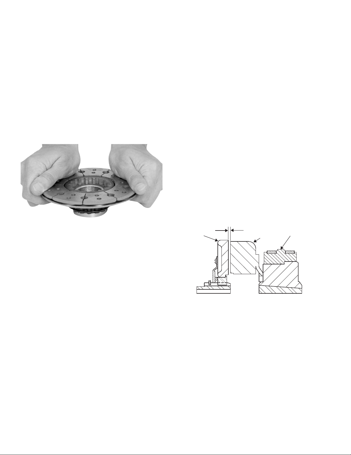
1. Determine which side of the magnet hub will be
mounted to the magnet. The hub is reversible.
The side to be used will depend on which side
the taperlock bushing is to enter.
Figure 2
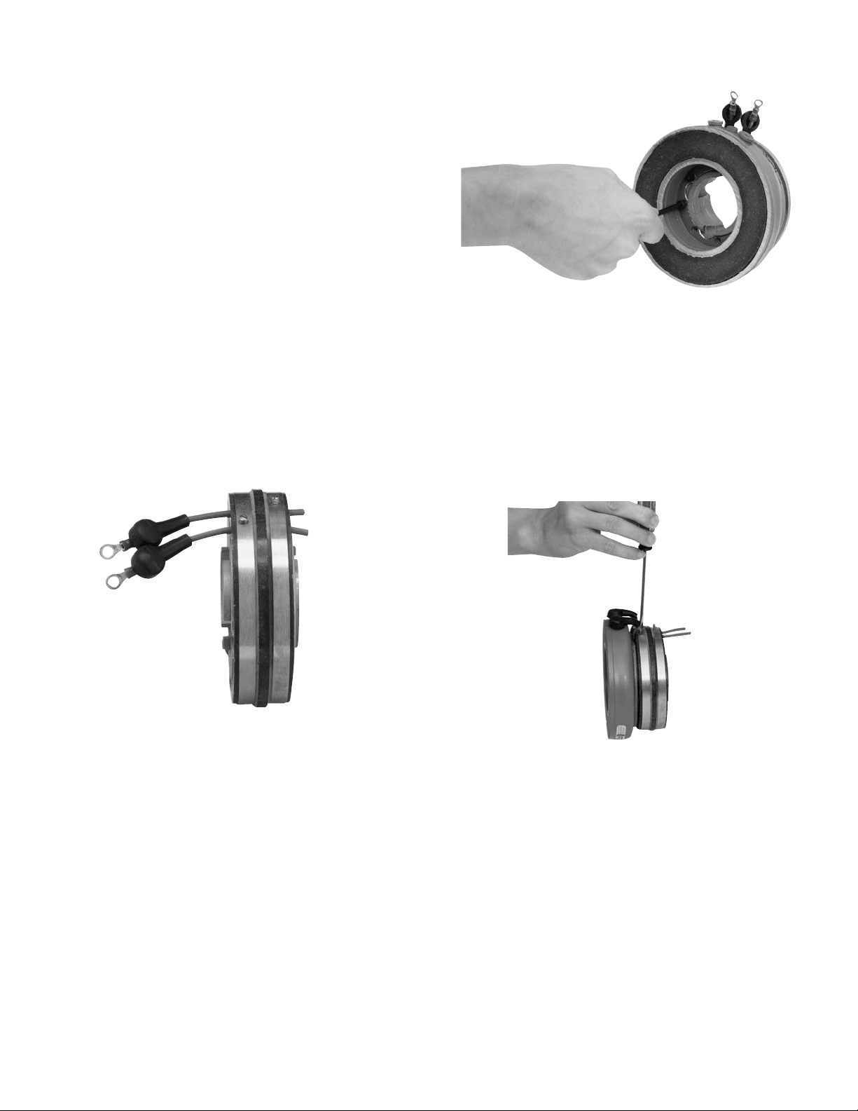
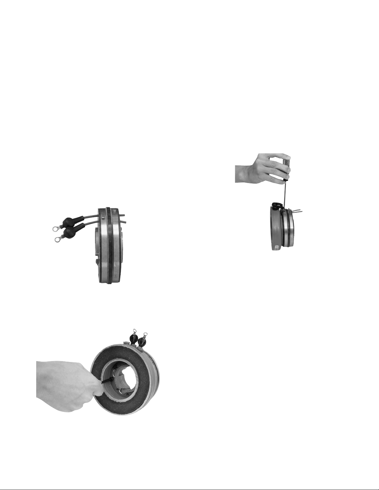
2. Insert the lead wires through the rubber
terminal caps and into the collector ring. The
wires should be inserted from the same side
of the ring that the magnet will be mounted on.
(Figure 1)
Figure 1
3. Mount the magnet to the magnet hub using
capscrews and lockwashers. (Figure 2)
7. Tighten down the screw in the collector ring.
The sharp cone point on the screw should
pierce the lead wire insulation to make a good
electrical contact. The head of the screw should
be below the surface of the collector ring.
(Figure 3)
8. Cut off the excess wire.
Figure 3
4. Secure the lead wires to the magnet terminals
with screws and lockwashers.
5. Pull the rubber terminal caps over the
terminals.
6. Pull the excess lead wire length from the
backside of the collector ring (away from the
magnet) until the wire is snug.
Warner Electric • 800-825-9050 819-0484
3
Page 4
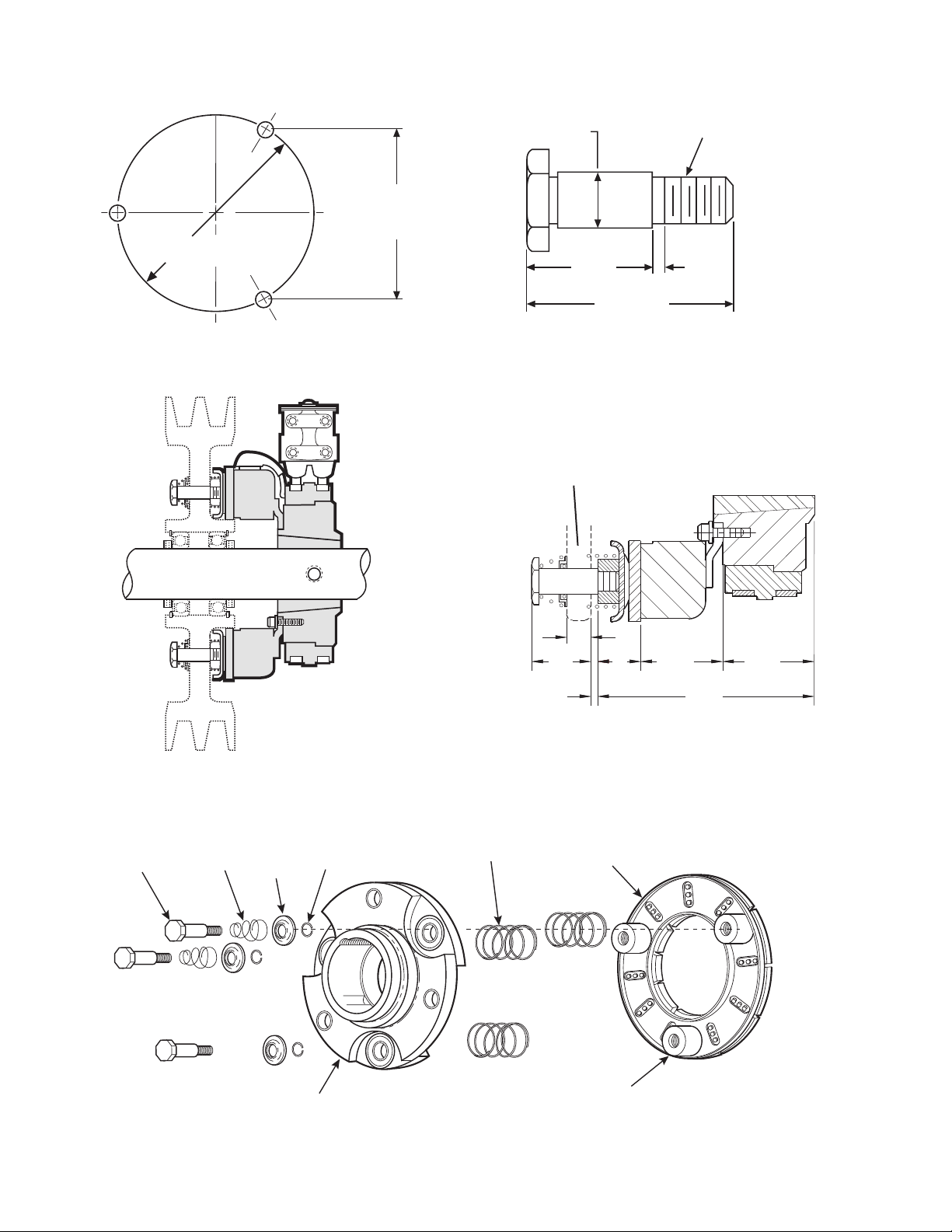
3.356 .001
Chordal
.3665 .0005 DIA.
3.875 .001
Bolt Circle
1/16
63/64
1-11/32
5/16 - 24 UNF - 3A
Threads
Mounting Instructions for Gear, Sprocket, or Pulley
Drive Pin
Conical
Spring
Retainer
Detent
Spring
Straight
Spring
Armature
Armature
Hub
Armature
Boss
Figure 4
Customer supplied
sheave or sprocket.
Figure 5 - PC Clutch
.062 When
.453
.968
New
.625
1.187
3.187
Figure 6
1.375
Warner Electric • 800-825-9050 819-0484
4
Figure 7
Page 5

B. Mounting the Magnet and Magnet Hub
C. Assembling the Armature
The magnet and magnet hub are mounted on the shaft
with a taperlock bushing. All parts must be
clean and free from burrs and chips before
assembling.
1. Place the bushing into the hub and insert the
key. The key is a side-to-side fit and should not
contact the top of the keyway.
2. Insert the locking setscrews loosely into the
bushing and slide the assembly onto the shaft.
3. If the armature has been secured to the shaft
first, then adjust the magnet's position to allow
approximately 1/32-inch between the two
faces. (Figure 12)
4. Secure the magnet's position on the shaft by
alternately tightening each setscrew with a
torque wrench to 175 in.lbs. torque. During the
tightening process the bushing should be
tapped lightly to make certain it seats-in
properly.
1. A customer may wish to use the autogap
accessory to mount a clutch armature to his
own pulley, hub, gear, etc. Follow the
illustrated dimensions (Figures 4, 8 and 9) to
properly adapt these parts to the armature.
a. The chordal dimension must be held for all
chords between pin holes.
b. Sleeve bearings (Oilite Bronze)
with an I.D. of .376 ±.001 must be
provided in the holes of pulley or hub at the
chordal and bolt circle dimensions shown in
Figure 4 and 6.
c. The drive pins must be square with plane of
mounting surface and magnet within .006
T.I.R.
2. Once the pulley, gear, etc., has been adapted
to the armature according to the above
directions, the ar ma ture may be mounted to
it using the autogap accessory.
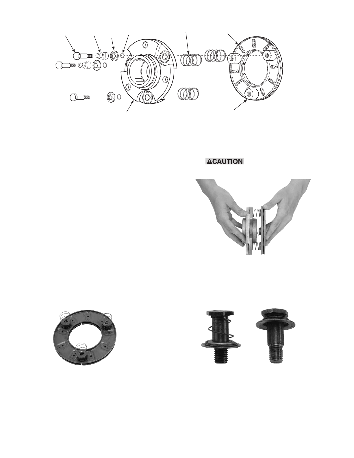
3. The autogap assembly is a double spring
device which allows for automatic armature
clearance and ad just ment for wear. The smaller
or conical spring pushes the armature from the
magnet face, leaving a gap of about 1/32 inch,
while the straight spring automatically follows
up for wear. This combination maintains
maximum performance efficiency throughout
the life of the unit. The assembly procedure for
the autogap accessory is as follows: (Figure 7)
Note: Autogap accessory is shipped
pre-assembled.
Warner Electric • 800-825-9050 819-0484
5
Page 6
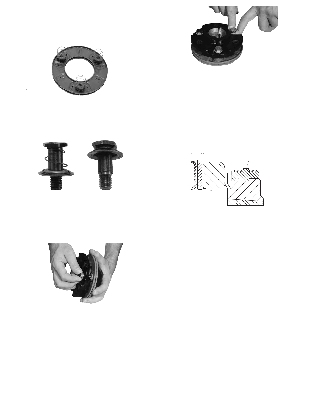
Step 1 Place straight springs over armature
1/32-inch
Armature
Magnet
Magnet Hub
bosses on back side of armature (Figure 8).
Figure 11
Note: This position must not be disturbed during
completion of as sem bly. (Figure 11)
Figure 8
Step 2 Compress conical spring against retainer ring
by sliding detent spring towards head of pin.
(All 3 pins.) (Figure 9)
Figure 9
Step 3 Insert assembled drive pins through
(customer-supplied part (Figure 5) through the
straight springs, and into the threaded armature bosses. Apply grade "AA" Loctite Sealant
on drive pin threads. (Figure 10)
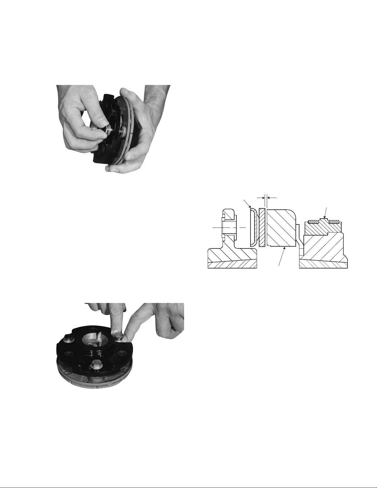
D. Mounting the Armature Assembly
1. Slide the armature assembly onto the shaft.
Keep adjustment in Step 5 (Figure 11) from
moving.
2. If the magnet and magnet hub assembly
Figure 12
has been secured to the shaft first, then adjust
the armature's position to allow approximately
1/32" between the two faces. (Figure 12)
Once this 1/32" gap has been set, it will be
automatically maintained throughout the life of
the unit.
3. Secure the assembly in this position on the
shaft.
E. Mounting the Brushholder
Figure 10
Step 4 Tighten drive pins until shoulders of pins are
against face of armature bosses. Since
threads are class No. 3 fit, pins may seem to
bind.
Step 5 Compress the retainer rings against the arma-
ture hub (or customer-supplied part), and
check to see that the part is held
tightly to the armature bosses.
Warner Electric • 800-825-9050 819-0484
6
1. The brushholder is mounted on a bracket which
must be furnished by the customer.
The bracket must be firmly secured to
prevent vibration which could cause
im proper contact between the brushes and collector ring.
2. The distance from the centerline of the shaft to
the top of the brushholder should be 4".
Maintaining this dis tance will assure proper
spring tension on the brushes and maximum
wear follow-up. A detailed dimensional
drawing is included with each brushholder.
Page 7
PCC-500 Clutch-Coupling
Heavy Duty Spline Drive Armature
The illustration drawings, parts list, and exploded view
for this unit can be found on pages 28 and 29.
Either the magnet half of the clutch unit or the
armature half of the unit may be mounted on the shaft
first, depending on the characteristics of each
application. (Figure 4)
A. Assembling the Magnet and Magnet
Hub
1. Determine which side of the magnet hub will be
mounted to the magnet. The hub is reversible.
The side to be used will depend on which side
the taperlock bushing is to enter.
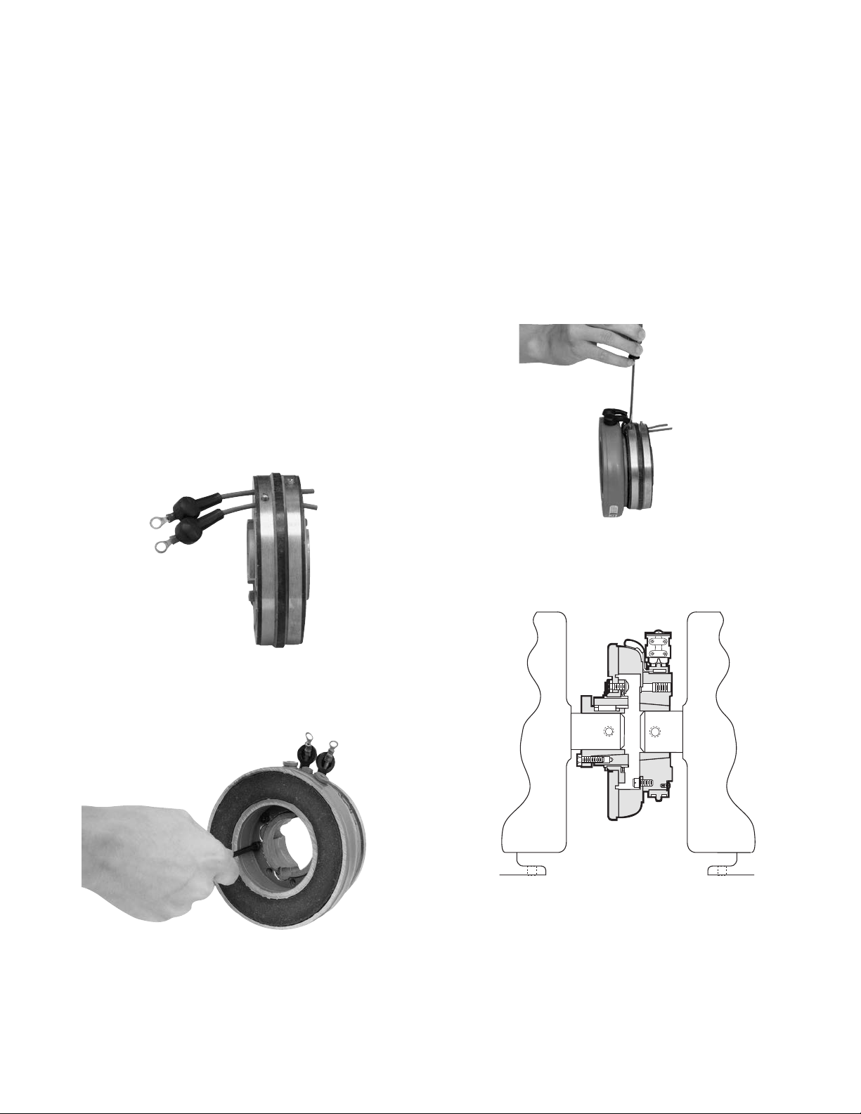
2. Insert the lead wires through the rubber
terminal caps and into the collector ring. The
wires should be inserted from the same side
of the ring that the magnet will be mounted on.
(Figure 1)
4. Secure the lead wires to the magnet
terminals with screws and lockwashers.
5. Pull the rubber terminal caps over the
terminals.
6. Pull the excess lead wire length from the backside of the collector ring (away from the magnet) until the wire is snug.
7. Tighten down the screw in the collector ring.
The sharp cone point on the screw should
pierce the lead wire insulation to make a good
electrical contact. The head of the screw should
be below the surface of the collector ring.
(Figure 3)
Figure 1
3. Mount the magnet to the magnet hub using
capscrews and lockwashers. (Figure 2)
Figure 3
8. Cut off the excess wire.
Figure 4 - PCC Clutch Coupling
Figure 2
Warner Electric • 800-825-9050 819-0484
7
Page 8
B. Mounting the Magnet and Magnet Hub
1/32-inch
Armature
Magnet
Magnet Hub
The magnet and magnet hub are mounted on the shaft
with a taperlock bushing. All parts must be clean and
free from burrs and chips before assembling.
1. Place the bushing into the hub and insert the
key. The key is a side-to-side fit and should not
contact the top of the keyway.
2. Insert the locking setscrews loosely into the
bushing and slide the assembly onto the shaft.
3. If the armature has been secured to the shaft
first, then adjust the magnets's position to allow
approximately 1/32-inch between the two faces.
(Figure 5)
Step 3 Holding the armature with the segmented side
up, press the armature onto the splined hub.
This is most easily done by applying firm
rocking back-and-forth pressure (Figure 5).
Step 4 Push the assembly against the retainer ring.
D. Mounting the Armature-Hub Assembly
1. Slide the armature-hub assembly onto the shaft
until the armature face touches the
magnet face.
2. Move the assembly back to allow a gap of
about 1/16-inch between the two faces.
3. Secure the armature-hub assembly in this
position by tightening the two setscrews in the
hub.
4. Check the assembly by pressing the
armature into contact with the magnet face and
then releasing it. The armature should spring
back about 1/32-inch. This gap will be
automatically maintained the life of the unit.
(Figure 6)
Figure 5
4. Secure the magnet's position on the shaft by
alternately tightening each setscrew with a
torque wrench to 175 in.lbs. torque. During
the tightening process the bushing should be
tapped lightly to make certain it seats-in
properly.
C. Assembling the Armature and Hub
The heavy duty units contain spline drive armatures and
hub. The armatures are shipped with a built-in autogap
spring accessory. This device automatically maintains a
gap of about 1/32-inch between the armature and
magnet faces for the life of the unit.
Follow these instructions to assemble the armature and
splined hub.
Step 1 Place the splined hub on a flat surface. The
extended portion of the hub, where the
setscrew holes are located, should be down.
Step 2 Check the detent ring in the armature
assembly to make sure it is centered evenly
around the spline. This ring moves freely, but it
should be centered for easier assembly of the
hub.
Figure 6
E. Mounting the Brushholder
1. The brushholder is mounted on a bracket which
must be furnished by the customer. The bracket
must be firmly secured to prevent vibration
which could cause im proper contact between
the brushes and collector ring.
2. The distance from the centerline of the shaft to
the top of the brushholder should be 4".
Maintaining this dis tance will assure proper
spring tension on the brushes and maximum
wear follow-up. A detailed dimensional
drawing is included with each brushholder.
Warner Electric • 800-825-9050 819-0484
8
Page 9
PCC-500 Clutch Coupling
Normal Duty Pin Drive Armature
4. Secure the lead wires to the magnet
terminals with screws and lockwashers.
The illustration drawing, parts list, and exploded view for
this unit can be found on pages 26 and 27.
Either the magnet half of the clutch unit or the
armature half of the unit may be mounted on the
shaft first, depending on the characteristics of each
application.
A. Assembling the Magnet and Magnet
Hub
1. Determine which side of the magnet hub will be
mounted to the magnet. The hub is
reversible. The side to be used will depend on
which side the taperlock bushing is to enter.
2. Insert the lead wires through the rubber
terminal caps and into the collector ring. The
wires should be inserted from the same side
of the ring that the magnet will be mounted on.
(Figure 1)
5. Pull the rubber terminal caps over the
terminals.
6. Pull the excess lead wire length from the backside of the collector ring (away from the magnet) until the wire is snug.
7. Tighten down the screw in the collector ring.
The shaft cone point on the screw should
pierce the lead wire insulation to make a good
electrical contact. The head of the screw should
be below the surface of the collector ring.
(Figure 3)
8. Cut off the excess wire.
Figure 1
3. Mount the magnet to the magnet hub using
capscrews and lockwashers. (Figure 2)
Figure 2
Figure 3
B. Mounting the Magnet and Magnet Hub
The magnet and magnet hub are mounted on the shaft
with a taperlock bushing. All parts must be clean and
free from burrs and chips before
assembling.
1. Place the bushing into the hub and insert the
key. The key is a side-to-side fit and should not
contact the top of the keyway.
2. Insert the locking setscrews loosely into the
bushing and slide the assembly onto the shaft.
3. If the armature has been secured to the shaft
first, then adjust the magnet's position to allow
approximately 1/32-inch between the two
faces. (Figure 10)
4. Secure the magnet's position on the shaft by
alternately tightening each setscrew with a
torque wrench to 175 in. lbs. torque. During the
tightening process the bushing should be
tapped lightly to make certain it seats-in
properly.
Warner Electric • 800-825-9050 819-0484
9
Page 10
Drive Pin
Conical
Spring
Retainer
Detent
Spring
Straight
Spring
Armature
Armature
Hub
Armature
Boss
Figure 4
C. Assembling the Armature and Hub
Assemble the armature to the armature hub with the
autogap mounting accessory. The hub is reversible. The
side on which the armature is mounted will depend on
the direction in which the taperlock
bushing must enter.
The autogap assembly is a double spring device which
allows for automatic armature clearance and adjustment
for wear. The smaller or conical spring pushes the
armature from the magnet face, leaving a gap of about
1/32-inch, while the straight spring automatically follows
up for wear. This combination maintains maximum
performance efficiency throughout the life of the unit.
The assembly procedure for the autogap accessory is as
follows: (Figure 4)
Note: Autogap accessory is shipped pre-assembled.
Step 1 Place straight springs over armature
bosses on backside of armature. (Figure 5)
Step 2 Place armature hub over straight springs.
Straight springs must fit into
grooves in ar ma ture hub. (Figure 6)
Figure 6
Step 3 Compress conical spring against retainer ring
by sliding detent spring towards head of pin.
(All 3 pins) (Figure 7)
10
Figure 5
Warner Electric • 800-825-9050 819-0484
Figure 7
Page 11
Step 4 Insert assembled drive pins through
1/32-inch
Magnet
Armature
Magnet Hub
armature hub and straight springs and into
the threaded armature bosses. Apply grade
"AA" Loctite Sealant on drive pin threads
(Figure 8)
Figure 8
Step 5 Tighten these (3) drive pins until shoulders of
pins are against face of armature bosses.
Since threads are class No. 3 fit, pins may
seem to bind.
Note: Alternately tighten each drive pin a
few turns at a time.
Step 6 Compress the retainers against the
armature hub and check to see that the
armature hub is held tightly to the armature
bosses.
Note: This position must not be disturbed
during completion of assembly.
(Figure 9)
Figure 9
Figure 10
Warner Electric • 800-825-9050 819-0484
11
Page 12

PCBC-500 Heavy Duty Spline Drive
Field
Pilot Diameter
Mounting Surface
Armature Clutch/Brake Coupling (Figure 2)
The illustration drawing, parts list, and exploded view for
this unit can be found on pages 32 and 33.
A. Installing the Conduit Box
Install the conduit box on the magnet. Instructions for
this procedure can be found on page 20.
B. Mounting the Magnet
The brake half of the clutch/brake unit is usually installed
first; however, in some cases it may be
necessary to start with the clutch portion of the unit
to assure a proper assembly when complete.
Figure 2 - PCBC Clutch/Brake Coupling
The brake magnet is mounted to a stationary machine
member by a flange. Extreme care must be taken in
se lect ing the location for the mounting of the magnet.
Proper positioning is very important for the unit to
function correctly.
1. A pilot diameter on the mounting surface is
essential to hold the magnet within the required
tolerances. (Figure 1) Also see “Customer Shall
Maintain” on page 32.
Figure 1
3. Once the mounting surface has been
prepared, the magnet is bolted in place with
capscrews and lock-washers. (Figure 3)
Figure 3
4. Use a dial indicator to check the unit for
concentricity and squareness to the shaft.
The unit should be concentric within .010 T.I.R.
and square within .006 T.I.R.
(Figure 4)
12
2. A machined pilot diameter is provided on the
magnet mounting flange (refer to illustration
drawings on page 32) to aid in the proper
positioning of the magnet.
Figure 4
Warner Electric • 800-825-9050 819-0484
Page 13

C. Assembling the Hub and Armatures
Magnet
1/32-inch
Armature
D. Mounting the Armature-Hub Assembly
The heavy duty units contain spline drive armatures and
hubs. The armatures are shipped with a built-in autogap
spring accessory. This device automatically maintains a
gap of about 1/32-inch between the
armature and magnet faces for the life of the unit.
Use the following method to assemble the armature and
splined hub:
1. Place the armature hub up on one end.
2. Check the detent ring in the armature
assembly to make sure it is evenly centered
around the spline. This ring moves freely, and it
should be centered for easier assembly of the
hub.
3. Holding one of the armatures with the
segmented side up, press the armature on
to the hub using firm rocking back-and-forth
pressure. (Figure 5)
1. Insert a key in the keyway of the hub and slide
the armature-hub assembly on to the shaft.
2. Position the assembly so that the face of the
armature is about 1/16-inch from the magnet
face.
3. Secure the armature-hub assembly in this
position by tightening the two setscrews in the
hub.
4. Check the assembly by pressing the armature
into contact with the magnet face and then
releasing it. The armature should spring
back about 1/32-inch. This gap will be
automatically maintained for the life of the unit.
(Figure 7)
Figure 5
4. Push the assembly up against the retainer ring.
5. Turn the hub over and repeat Steps 3 and 4
with the other armature. (Figure 6)
Figure 6
Figure 7
Warner Electric • 800-825-9050 819-0484
13
Page 14

E. Assembling the Magnet and Magnet
Hub
1. Determine which side of the magnet hub will be
mounted to the magnet. The hub is reversible.
The side to be used will depend on which side
the taperlock bushing is to enter.
2. Insert the lead wires through the rubber
terminal caps and into the collector ring. The
wires should be inserted from the same side of
the ring that the magnet will be mounted on.
(Figure 8)
Figure 8
7. Tighten down the screw in the collector ring.
The sharp cone point on the screw should
pierce the lead wire insulation to make a good
electrical contact. The head of the screw should
be below the surface of the collector ring.
(Figure 10)
Figure 10
8. Cut off the excess wire.
Figure 9
3. Mount the magnet to the magnet hub using
capscrews and lockwashers. (Figure 9)
4. Secure the lead wires to the magnet terminals
with screws and lockwashers.
5. Pull the rubber terminal caps over the
terminals.
6. Pull the excess lead wire length from the backside of the collector ring (away from the magnet) until the wire is snug.
Warner Electric • 800-825-9050 819-0484
14
Page 15

F. Mounting the Magnet and Magnet Hub
1/32-inch
Armature
Magnet Hub
Magnet
G. Mounting the Brushholder
The magnet and magnet hub are mounted on the shaft
with a taperlock bushing. All parts must be clean and
free from burrs and chips before assembling.
1. Place the bushing into the hub and insert the
key. The key is a side-to-side fit and should not
contact the top of the keyway.
2. Insert the locking setscrews loosely into the
bushing and slide the assembly onto the shaft.
3. Adjust the magnet's position to allow a gap of
about 1/16 inch between the magnet face and
the armature face.
4. Secure the magnet's position on the shaft by
alternately tightening each setscrew with a
torque wrench to 175 in. lbs. torque. During the
tightening process the bushing should be
tapped lightly to make certain it seats-in
properly.
5. Set the autogap by pressing the armature
into contact with the magnet face and then
releasing it. The armature should spring back
about 1/32 inch. (Figure 11)
1. The brushholder is mounted on a bracket which
must be furnished by the customer. The
bracket must be firmly secured to prevent
vibration which could cause im proper contact
between the brushes and collector ring.
2. The distance from the centerline of the shaft to
the top of the brushholder should be 4".
Maintaining this dis tance will assure proper
spring tension on the brushes and maximum
wear follow-up. A detailed dimensional
drawing is included with each brushholder.
This gap will be automatically maintained for the
life of the unit.
Figure 11
Warner Electric • 800-825-9050 819-0484
15
Page 16

PCBC-500 Clutch/Brake Coupling
Field
Pilot Diameter
Mounting Surface
Normal Duty Pin Drive Armature (Figure 2)
The illustration drawing, parts list, and exploded view for
this unit can be found on pages 30 and 31.
A. Installing the Conduit Box
Install the conduit box on the magnet. Instructions for
this procedure can be found on page 20.
B. Mounting the Magnet
The brake half of the clutch/brake unit is usually installed
first; however, in some cases it may be
necessary to start with the clutch portion of the unit
to assure a proper assembly when complete.
3. Once the mounting surface has been
prepared the magnet is bolted in place with
capscrews and lockwashers. (Figure 3)
Figure 3
The brake magnet is mounted to a stationary machine
member by a flange. Extreme care must be taken in
se lect ing the location for the mounting of the magnet.
Proper positioning is very important for the unit to
function correctly.
1. A pilot diameter on the mounting surface is
essential to hold the magnet within the required
tolerances. (Figure 1) Also see “Customer Shall
Maintain” on page 34.
Figure 1
2. A machined pilot diameter is provided on the
magnet mounting flange (refer to illustration
drawings pages 30 and 31) to aid in the proper
positioning of the magnet.
Figure 2 - PCBC Clutch/Brake Coupling
4. Use a dial indicator to check the unit for
concentricity and squareness to the shaft.
The unit should be concentric within .010 T.I.R.
and square within .006 T.I.R. (Figure 4)
Figure 4
C. Assembling the Hub and Armatures
Assemble the armatures to the armature hub with the
auto gap mounting accessory. The hub is reversible so
that the taperlock bushing may be inserted from either
side as required.
The autogap assembly is a double spring device which
allows for automatic armature clearance and adjustment
for wear. The smaller or conical spring pushes the
armature from the magnet face, leaving a gap of about
1/32 inch, while the straight spring automatically follows
up for wear. This combination maintains maximum performance efficiency throughout the life of the unit.
Warner Electric • 800-825-9050 819-0484
16
Page 17

Armature Boss
Armature Hub
Drive Pin
Conical
Spring
Retainer
Detent Spring
Straight
Spring
Armature
The assembly procedure for the autogap accessory is as
follows (refer to Figure 5):
Note: Autogap accessories are shipped
pre-assembled.
Step 1 Place straight springs over armature bosses
on back side of both armatures. (Figure 6)
Figure 6
Figure 5
Step 4 Insert the remaining (3) drive pins from the oppo-
site side of the armature hub through the remaining (3) holes.
Note: Apply Grade "AA" Loctite Sealant
on threads of all (6) drive pins. (Figure 8)
Step 5 Holding the pins in position, place the
armature hub over one armature. Make
Figure 8
sure the straight springs on the armature bosses
fit into the groove in the armature hub (Figure 9).
Step 2 Compress conical spring against retainer ring
Figure 7
by sliding detent spring toward head of pin.
(All 6 pins.) (Figure 7)
Step 3 Insert (3) of the compressed drive pins
through the armature hub. The threaded ends
of the pins must come through on the side of
the hub with grooves around the holes.
Figure 9
Warner Electric • 800-825-9050 819-0484
17
Page 18

1/32-inch
Magnet
Armature
Step 6 Tighten these (3) drive pins until shoulders of
pins are against face of armature bosses.
Since threads are class No. 3 fit, pins may
seem to bind.
Note: Alternately tighten each drive pin a
few turns at a time.
Step 7 Repeat Steps 5 and 6 for the second
armature. (Figures 10 & 11)
Figure 10
D. Mounting the Armature Assembly
The armature and armature hub are mounted on the
shaft with a taperlock bushing. All parts must be clean
and free from burrs and chips before assembling.
1. Place the bushing into the hub and insert the
key. The key is a side-to-side fit and should not
contact the top of the keyway.
2. Insert the locking setscrews loosely into the
bushing and slide the assembly onto the shaft.
3. Place the face of the armature approximately
1/32 inch from the face of the magnet. Once
this gap is set, it will be automatically
maintained throughout the life of the unit.
Figure 11
Step 8 Compress the armature hub and one of the
armatures together until the armature hub bottoms on the armature boss. Slide the retainer
on each pin down tightly against the armature
Figure 12
hub. (Figure 12)
Step 9 Turn the assembly over and repeat Step 8 for
the second armature.
Note: This position must not be dis turbed
during completion of the assembly.
Figure 13
(Figure 13)
4. Secure the armature's position on the shaft
by al ter nately tightening each setscrew. During
the tightening process, the bushing should be
tapped lightly to make certain it seats-in
properly.
E. Assembling the Magnet and Magnet
Hub
1. Determine which side of the magnet hub will be
mounted to the magnet. The hub is reversible.
The side to be used will depend on which side
the taperlock bushing is to enter.
2. Insert the lead wires through the rubber
terminal caps and into the collector ring. The
wires should be inserted from the same side
of the ring that the magnet will be mounted on.
(Figure 14)
Warner Electric • 800-825-9050 819-0484
18
Page 19

F. Mounting the Magnet and Magnet Hub
1/32-inch
Magnet Hub
Armature
Magnet
The magnet and magnet hub are mounted on the shaft
with a taperlock bushing. All parts must be clean and
free from burrs and chips before assembling.
1. Place the bushing into the hub and insert the
key. The key is a side-to-side fit and should not
contact the top of the keyway.
Figure 14
3. Mount the magnet to the magnet hub using
capscrews and lockwashers. (Figure 15)
Figure 15
4. Secure the lead wires to the magnet terminals
with screws and lockwashers.
5. Pull the rubber terminal caps over the
terminals.
6. Pull the excess lead wire length from the backside of the collector ring (away from the magnet)
until the wire is snug.
7. Tighten down the screw in the collector ring.
The sharp cone point on the screw should
pierce the lead wire insulation to make a good
electrical contact. The head of the screw should
be below the surface of the collector. (Figure 16)
2. Insert the locking setscrews loosely into the
bushing and slide the assembly onto the shaft.
3. Adjust the magnet's position to allow a gap of
1/32 inch between the magnet face and the
armature face. (Figure 17)
Figure 17
Once this gap is set, it will be automatically
maintained for the life of the unit.
4. Secure the magnet's position on the shaft by
alternately tightening each setscrew with a
torque wrench to 175 in. lbs. maximum torque.
During the tightening process the bushing
should be tapped lightly to make
certain it seats-in properly.
G. Mounting the Brushholder
1. The brushholder is mounted on a bracket which
must be furnished by the customer. The bracket
must be firmly secured to prevent vibration
which could cause im proper contact between
the brushes and collector ring.
2. The distance from the centerline of the shaft to
the top of the brushholder should be 4".
Maintaining this dis tance will assure proper
Figure 16
8. Cut off the excess wire.
Warner Electric • 800-825-9050 819-0484
spring tension on the brushes and maximum
wear follow-up. A detailed dimensional
drawing is included with each brushholder.
19
Page 20

Installation Instructions
4
10
8
11
12
7
3
6
5
9
9-1
2
1
4
Conduit Box Kit No. 5200-101-010
Description
This Warner Electric conduit box is designed to
provide a proper means for field wiring terminations. It
conforms to the requirements of Underwriters
Laboratories. Kit No. 5200-101-010, plus magnet
terminal accessory kit, contains all components
needed to assemble a conduit box for the above
mentioned units. Please follow these instructions
carefully when installing this conduit box. Failure to
comply with these instructions could result in unsafe
electrical con nec tions.
Parts List for Kit 5200-101-010
Item Quan. Part Name
11Bracket
21Screw, Hex, Washer Hd.
and Sems Conical Washer
31Box, Conduit
43Screw, Hex. Washer Hd.
51Plug, Protective
62Grommet, Wire
72Spacer, Terminal
82Cap, Terminal
91Screw, Hex. Washer Hd.
9-1 1 Terminal, Ring
10 1 Cover Assembly
*11 2 Screw No. 6 Brass
2 Screw No. 8 Brass
†12 2 Terminal, Ring
* The No. 6 screws are required on Sizes 375, 400, and 475. All
others use No. 8.
Warner Electric • 800-825-9050 819-0484
20
† Terminal Ring provided with terminal accessory kit 5311-101-003,
5311-101-001 respectively, supplied with magnets.
Note: All mounting screws are self-tapping.
Page 21

Step 1 Fasten bracket (1) to the clutch or brake with
one No. 10-32 hex. washer head screw and
washer (2). The square pro jec tion on the
clutch or brake between the terminals is to be
assembled into the square hole in the bracket.
The bracket flange is installed toward the back
of the unit. (Figure 1)
Figure 1
Step 2 Assemble a 1/2" flexible conduit fitting into the
desired end of the conduit box (3). If
the grounding nut on this conduit fitting is
tightened after the conduit box is installed on
the magnet or field, avoid using excessive
tapping force, which could damage the
mounting. (Step 6)
Step 3 Mount conduit box (3) to the bracket (1).
The conduit box flange must be toward the
back of the clutch or brake. Secure the box
with two No.10-32 hex. washer head screws
(4). (Figure 2)
Step 5 Push two terminal spacers (7) through the
grommets with the spacer flanged ends inside
the conduit box. (See Figure 3)
Figure 3
Step 6 Connect electric supply cable to the fitting
installed on the conduit box. Use D.C.
supply only.
Rigid conduit must not be
connected directly to the
box. A minimum of 12" of flexible cable
must be used. It is rec om mended that
flexible "UL" listed liquid-tight, metallic or
non-metallic conduit, meeting local
codes, be used with ap pro pri ate fittings.
Flexible cable is required to prevent side
loading of bearing on bearing mounted
clutches and brakes and possible
deformation of the conduit box or
components during assembly.
Step 7 Press protective plug (5) into the unused
conduit hole in the box.
Step 8 Slide one rubber cap (8) onto each of the two
supply conductors, small end first. Connect
the two supply con duc tors (with rubber caps)
to the magnet or field
terminals using two No. 6 or No. 8 screws
(11). Use wire retaining ring terminals
supplied with the clutch or brake terminal
ac ces sory. The stripped wires may be
wrapped around the screw between the wire
terminal ring and the screw head or other ring
type terminals such as "AMP" may be used.
Figure 2
Step 4 Snap the two rubber grommets (6) into two
square holes in the bottom of the conduit box.
The grommet crowns should be in the box
and the rubber flanges should be on both
sides of the metal floor. (Figure 3)
Warner Electric • 800-825-9050 819-0484
The screws are then assembled through the
terminal spacers (7) and threaded into the
clutch or brake terminals.
21
Page 22

Coil Data
Unit Size PB & PC-500
Voltage – DC 6 24 90
Resistance @ 20°C — Ohms 1.36 23.8 251.1
Current — Amperes 4.4 1.01 .36
Watts 26 24 32
Coil Build-up — Milliseconds 84 87 93
Coil Decay — Milliseconds 38 35 30
Note: Build-up time equals current to approximately 90% of steady state value and flux to 90%.
Decay time equals current to approximately 10% of steady state value and flux to 10%.
Note: Times are approximately because current leads or lags flux by a small amount.
Warner Electric • 800-825-9050 819-0484
22
Page 23

Burnishing and Maintenance
Burnishing
Intimate metal to metal contact is essential between the
armature and the metal rings (poles) of the magnet or
rotor. Warner Electric clutches and brakes leave the
factory with the friction material slightly undercut to
assure good initial contact.
Normally, the desired wearing-in process occurs
naturally as the surfaces slip upon engagement. The time
for wear-in, which is necessary to obtain the ultimate
torque of the unit, will vary depending on speed, load, or
cycle duty.
If maximum torque is required immediately after
installation, the unit should be burnished by slipping the
friction surfaces together at reduced voltage. It is
recommended that the burnishings be done right on
the application, if at all possible.
Burnishing at high speed will result in a smoother wear-in
pattern and reduce the time for burnishing. The voltage
should be set at approximately 30% or 40% of the rated
value.
The unit should be cycled on and off to allow sufficient
time between slip cycles to prevent overheating.
When a Warner Electric brake or clutch is properly
as sembled and installed, no further servicing,
lubrication, or maintenance should be required
throughout the life of the unit.
Foreign Materials: If units are used on machinery
where fine, abrasive dust, chips or grit are dispelled into
the atmosphere, shielding of the brake may be
necessary if maximum life is to be obtained.
Where units are used near gear boxes or transmissions
requiring frequent lubrication, means should be provided
to protect the friction surfaces from oil and grease to
prevent serious loss of torque.
Oil and grease accidently reaching the friction surfaces
may be removed by wiping with a rag dampened
with a suitable cleaner, which leaves no residue. In
performing this operation, do not drench the friction
material.
If the friction materials have been saturated with oil or
grease, no amount of cleaning will be completely
effective. Once such a unit has been placed back in
service, heat will cause the oil to boil to the surface,
resulting in further torque loss.
Torque Loss: If a brake or clutch slips or loses torque
completely, the initial check should be the input
voltage to the magnet as follows:
90-Volt Series: Connect a DC voltmeter with a range of
0-100 or more directly across the magnet terminals. With
the power on and the potentiometer turned up, a normal
reading is 90 volts, although 85 to 95 is satisfactory. The
reading should drop as the potentiometer control is
adjusted counter clock wise.
24-Volt Series: Use a DC voltmeter with a range of
0-30 volts or more. A normal reading is approximately
22-26 volts.
Maintenance
Wear Pattern: Wear grooves appear on the armature
and magnet surfaces. This is a normal wear condition,
and does not impair functioning of the unit. Normally, the
magnet and armature, as a mating pair, will wear at the
same rate. It is the usual recommendation that both
components be replaced at the same time.
Remachining the face of a worn armature is not
rec om mended. If a replacement armature is to be used
with a used magnet, it is necessary to remachine the
worn magnet face. In refacing a magnet: (1) machine
only enough material to clean up the complete face of
the magnet; (2) hold the face within .005" of parallel with
the mounting plate; and (3) undercut the molded facing
material .002" - .004" below the metal poles.
Heat: Excessive heat and high operating temperatures
are causes of rapid wear. Units, therefore, should be
ven ti lated as efficiently as possible, especially if the
application requires fast, repetitive cycle operation.
Warner Electric • 800-825-9050 819-0484
6-Volt Series: Use a DC voltmeter of approximately
0-15 volt range. A normal reading is from 5.5 to 6.5
volts.
The above checks are normally sufficient. Further checks
may be made as follows: a low range ammeter, when
connected in series with one magnet lead, will normally
indicate approximately .40 amperes for the 90 volt units,
1.0 ampere for the 24 volt, and 3.5 amperes for the 6
volt series. These readings are with the power on and
the potentiometer control in the maximum position.
Ohmmeter checks should be made with the power off
and the circuit open (to be certain, disconnect one lead
to the magnet). Average resistance for the 90 volt series
is 220 ohms; for the 24 volt, 20 ohms; and for the 6 volt
series, 1.5 ohms. A very high or infinite resistance
reading would indicate an open coil.
If the above checks indicate that the proper voltage and
current is being supplied to the magnet, mechanical
parts should be checked to assure that they are in good
operating condition and properly installed.
23
Page 24

PC-500 Clutch
See page 4 for details on drive
pin mountings.
1/2-14 NPSM Am. std.
straight pipe tap.
Armature View
5.937
Max.
Dia.
5.062
Dia.
.062 When
New
.968
.453
.625
3.468
1.187
3.187
.171 Max.
4
1.50
Max.
1.375
See page
34 for
details on
Bushings.
Collector Ring View
Customer Shall Maintain:
1. Armature mounting to be concentric with
magnet hub asasembly within .006 T.I.R.
Shaft Size .500 – 1.250
Static Torque 40 lb.ft.
Maximum Speed 5,400 RPM
Standard Voltage D.C. 6, 24, 90
Warner Electric • 800-825-9050 819-0484
24
Page 25

PC-500 Clutch Drawing I-25716
2
2-1
1-1
1-2
4-1
1 Shipped As sem bled
4
7
Item Description Part Number Qty.
1 Magnet Hub 5300-541-001 1
1-1 Collector Ring 5300-749-001 1
1-2 Collector Ring Mounting Acc. 5300-101-002 1
2 Brushholder 5300-178-001 1
2-1 Brush 176-0001 4
3 Bushing 1
1/2" to 1-1/4" Bore 180-0116 to 180-0128* 1
4 Magnet 1
6 Volt 5300-631-002
24 Volt 5300-631-003
90 Volt 5300-631-005
4-1 Terminal Accessory 5311-101-001 1
5 Armature 5300-111-002 1
6 Autogap Accessory 5200-101-009 3
7 Mounting Accessory 5102-101-0001 4
*See page 34 for specific part numbers.
3
6
5
How to Order:
1. Specify Bore Size for Item 3.
2. Specify Voltage for Item 4.
3. See P-1234 for Power Supplies.
Example:
PC-500 Clutch per I-25716 - 90 Volt 3/4" Bore
These units, when used in conjunction with the
correct Warner Electric conduit box, meet the
standards set of forth in UL508 and are listed under
guide card #NMTR2, file #59164.
These units are CSA certified under file #LR11543.
Warner Electric • 800-825-9050 819-0484
25
Page 26

PCC-500 Clutch Coupling Normal Duty
See page 38 for details on
Bush ings.
.171
3.578
4
5.937
Max.
1/2-14 NPSM Am. std.
straight pipe tap.
See page 34
for details on
Bush ings.
Armature View
5
Dia.
.062
Min. running
clearance
.453
1.50 Max.
.062 when new
1.343
1.187 1.375
4.406
1.50
Armature Shaft .500 – 1.250
Rotor Shaft .500 – 1.250
Static Torque 40 lb.in.
Maximum Speed 5,400 RPM
Standard Voltage D.C. 6, 24, 90
Collector Ring View
Customer Shall Maintain:
1. Armature mounting shaft concentric with
magnet mounting shaft within .006 T.I.R.
Warner Electric • 800-825-9050 819-0484
26
Page 27

PCC-500 Clutch Coupling Normal Duty Drawing I-25542
4
4-1
3-1
3-2
6-1
3 Shipped Assembled
6
8
7
Item Description Part Number Qty.
1 Armature Hub 5300-541-004 1
2 Armature 5300-111-002 1
3 Magnet Hub 5300-541-001 1
3-1 Collector Ring 5300-749-001 1
3-2 Collector Ring Mounting Acc. 5300-101-002 1
4 Brushholder 5300-178-001 1
4-1 Brush 176-0001 4
5 Bushing
1/2" to 1-1/4" Bore 180-0116 to 180-0128* 2
6 Magnet
6 Volt 5300-631-002
24 Volt 5300-631-003
90 Volt 5300-631-005
6-1 Terminal Accessory 5311-101-001 1
7 Autogap Accessory 5200-101-009 3
8 Mounting Accessory 5102-101-001 2
*See page 34 for specific part numbers.
5
5
1
2
How to Order:
1. Specify Bore Size for Item 5.
2. Specify Voltage for Item 6.
3. See P-1234 for Power Supplies.
Example:
PCC-500 Clutch Coupling per I-25542 - 90 Volt 3/4"
Bore
These units meet standards set forth in UL508 and are
listed under guide card #NMTR2, file #59164.
These units are CSA certified under file #LR11543.
Warner Electric • 800-825-9050 819-0484
27
Page 28

PCC-500 Clutch Coupling Heavy Duty
For Bore & Keyway sizes see
chart below.
Armature View
5.937
Max.
5.125
Dia.
1.500
1.203
Max.
.171
2.953
4
.171
See page 34 for
details on
Bushings.
1/2-14 NPSM Am. std. straight
Collector Ring View
Customer Shall Maintain:
1. Armature mounting shaft concentric with
magnet mounting shaft within .006 T.I.R.
pipe tap.
.062 when new
.375
1.187
3.703
1.375
Bore & Keyway Dimensions
Rotor
Bore Dia. Keyway
.751/.750 .187 x .093
.876/.875
.9385/.9375
1.001/1.000 .250 x .125
1.126/1.125
1.251/1.250
Armature Shaft .750 – 1.250
Rotor Shaft .500 – 1.250
Static Torque 40 lb.in.
Maximum Speed 5,400 RPM
Standard Voltage D.C. 6, 24, 90
Warner Electric • 800-825-9050 819-0484
28
Page 29

PCC-500 Clutch Coupling Heavy Duty Drawing I-25543
6-1
2-1
4
4-1
3-2
3-1
5
3
Shipped Assembled
2
2-3
2-4
2-5
2-2
1
7
Item Description Part Number Qty.
1 Armature Hub 1
3/4" Bore 5200-541-002
7/8" Bore 5200-541-003
15/16" Bore 5200-541-004
1" Bore 5200-541-005
1-1/8" Bore 5200-541-006
1-1/4" Bore 5200-541-007
2 Armature Assembly 5230-111-002 1
2-1 Armature 5230-111-001 2
2-2 Retainer Ring 748-0355 1
2-3 Autogap Spring 808-0412 1
2-4 Retainer Plate 748-0364 1
2-5 Screw 797-0028 3
3 Magnet Hub 5300-541-001 1
3-1 Collector Ring 5300-749-001 1
3-2 Collector Ring Mounting Acc. 5300-101-002 1
4 Brushholder 5300-178-001 1
4-1 Brush 176-0001 4
5 Bushing
1/2" to 1-1/4" Bore 180-0116 to 180-0128* 2
6
Item Description Part Number Qty.
6 Magnet 1
6 Volt 5300-631-002
24 Volt 5300-631-003
90 Volt 5300-631-005
6-1 Terminal Accessory 5311-101-001 1
7 Mounting Accessory 5102-101-001 2
*See page 34 for specific part numbers.
How to Order:
1. Specify Bore Size for Item 1 and Item 5.
2. Specify Voltage for Item 6.
3. See P-1234 for Power Supplies.
Example:
PCC-500 Clutch Coupling per I-25543 - 90 Volt
3/4" Armature Hub Bore 1" Bushing Bore
These units meet standards set forth in UL508 and are
listed under guide card #NMTR2, file #59164.
These units are CSA certified under file #LR11543.
Warner Electric • 800-825-9050 819-0484
29
Page 30

PCBC-500 Clutch/Brake Coupling Normal Duty
1/2-14 NPSM
Am. std. straight
pipe tap.
See page 34 for
details on
Bushings.
Collector Ring View
3.750
Removable plug in
ends for 1/2" con-
duit.
.171
4
5.937
Running
Dia. Max.
1.500
1.343
5.859
5.125
5.031
2.031
.062
When
New
1.500
1.546
1.093
1.031
1.187
1.468
1.546
.390
8-32 UNC-3A
5.062
2.687
2.065
2.063
Pilot
Dia.
3.953
5.062 Max.
.208/.201 dia. (8) holes
equally spaced on 2.375
45°
6.500/6.498 Pilot Dia.
dia.*
5
.399/.389 dia. (4) holes
equally spaced on 5.875
dia.**
Magnet View
(Inside & Outside Mounted)
* Mounting holes are within .010 of true position relative to pilot
diameter.
** Mounting holes are within .008 of true position relative to pilot
diameter.
Customer Shall Maintain:
1. Squareness of brake mounting face with
armature hub shaft within .006 T.I.R.
.062
When
New
1.375
5.937
1.281
Outside Mounted Offset Backing Plate
1.390
.468
Max.
4.968
5.781 Max.
.953
Outside Mounted Flush Backing Plate
Armature Shaft .500 – 1.250
Magnet Shaft .500 – 1.250
Static Torque 40 lb.ft.
Maximum Speed 5,400 RPM
Standard Voltage D.C. 6, 24, 90
3/8-16
UNC-2A
.515
1.125
2. Concentricity of brake mounting pilot
di am e ter with ar ma ture hub shaft within
.010 T.I.R.
3. Concentricity of clutch magnet hub assembly
shaft with armature hub shaft within .006 T.I.R.
Warner Electric • 800-825-9050 819-0484
30
Page 31

PCBC-500 Clutch/Brake Coupling Normal Duty Drawing I-25547
1
Shipped
As sem bled
1-1
6
2
2-1
1-2
4-1
4
5
10A
3
9A
7
6
8
11
10A-1
3
11
10B-1
10C-1
10B
10C
Item Description Part Number Qty.
1 Magnet Hub 5300-541-001 1
1-1 Collector Ring 5300-749-001 1
1-2 Collector Ring Mounting Access. 5300-101-002 1
2 Brushholder 5300-178-001 1
2-1 Brush 176-0001 4
3 Bushing
1/2" - 1/4" Bore 180-0116 to 180-0128* 2
4 Magnet, Clutch 1
6 Volt 5300-631-002
24 Volt 5300-631-003
90 Volt 5300-631-005
4-1 Terminal Accessory 5311-101-001 1
5 Mounting Accessory 5102-101-001 2
6 Armature 5300-111-002 2
7 Autogap Accessory 5200-101-009 6
8 Armature Hub 5300-541-004 1
9A Mounting Accessory - I.M. 5102-101-001 2
9B Mounting Accessory - O.M. 5300-101-008 1
10A Magnet - I.M. 1
6 Volt 5300-631-002
24 Volt 5300-631-003
90 Volt 5300-631-005
10A-1 Terminal Accessory 5311-101-001 1
10B Magnet - O.M. - Offset 1
90 Volt 5300-631-014
10B-1 Terminal Accessory 5311-101-001 1
9B
Item Description Part Number Qty.
10C Magnet - O.M. - Flush 1
6 Volt 5300-631-009
24 Volt 5300-631-010
90 Volt 5300-631-011
10C-1 Terminal Accessory 5311-101-001 1
11 Conduit Box 5200-101-010 1
*See page 34 for specific part numbers.
How to Order:
1. Specify Bore Size for Item 3.
2. Specify Voltage for Item 4 and Item 10A, 10B
or 10C.
3. Specify Inside Mount ed for Item 10A and
Outside Mounted (Offset) for Item 10B or
Outside Mounted (Flush) for Item 10C.
4. See P-1234 for Power Supplies.
Example:
PCBC-500 Clutch Brake Coupling per I-25547 - 90
Volt, Inside Mount ed, 1" Bore
These units meet the standards of UL508 and are listed
under guide card #NMTR2, file #59164. These units are
CSA certified under file #LR11543.
Warner Electric • 800-825-9050 819-0484
31
Page 32

PCBC-500 Clutch/Brake Coupling Heavy Duty
1/2-14 NPSM Am. std.
straight pipe tap.
See page 34 for
details on Bushings.
.171
.062
When
New
5.812
5.031
4.953
1.937
1.546
1.093
1.031
1.187
Collector Ring View
3.750
Removable plug in ends for
For Bore
& Keyway sizes see
chart below. .208/.201 dia. (8) holes
6.500/6.498 Pilot Dia.
5.062
45°
.399/.389 dia. (4) holes equally spaced
1/2" conduit.
equally spaced on 2.375
dia.*
5
on 5.875 dia.**
Magnet View
(Inside & Outside Mounted)
* Mounting holes are within .010 of true position relative to pilot
diameter.
** Mounting holes are within .008 of true position relative to pilot
diameter.
Bore and Keyway Dimensions
Armature
Bore Dia. Keyway
.751/.750 .187 x .093
.876/.875
.9385/.9375
1.001/1.000
1.126/1.125 .250 x .125
1.251/1.250
Customer Shall Maintain:
1. Squareness of brake mounting face with
armature hub shaft within .006 T.I.R.
2. Concentricity of brake mounting pilot
diameter with ar ma ture hub shaft within
.010 T.I.R.
4
5.937
Running
Dia. Max.
5.125
1.500
1.375
.062
When
New
5.890
2.375
.984
1.062
1.281
.390
8-32
UNC-
2.065
2.063
2.062
Outside Mounted Offset Backing Plate
.906
.953
4.875
5.734 Max.
1.125
1.468 Max.
Outside Mounted Flush Backing Plate
Armature Shaft .500 – 1.250
Magnet Shaft .750 – 1.250
Static Torque 40 lb.ft.
Maximum Speed 5,400 RPM
Standard Voltage D.C. 6, 24, 90
3.953
Pilot
3A
Dia.
3/8-16
UNC-2A
.515
3. Concentricity of clutch magnet hub assembly
shaft with armature hub shaft within .006 T.I.R.
Warner Electric • 800-825-9050 819-0484
32
Page 33

PCBC-500 Clutch/Brake Coupling Heavy Duty Drawing I-25553
10
1
Shipped
As sem bled
2
2-1
1-2
1-1
4-1
4
9A-1
9A
5
8A
3
10
6
9B-1
9C-1
7
9B
9C
6
Item Description Part Number Qty.
1 Magnet Hub 5300-541-001 1
1-1 Collector Ring 5300-749-001 1
1-2 Collector Ring Mounting Access. 5300-101-002 1
2 Brushholder 5300-178-001 1
2-1 Brush 176-0001 4
3 Bushing
1/2" - 1-1/4" Bore 180-0116 to 180-0128 1
4 Magnet, Clutch 1
6 Volt 5300-631-002
24 Volt 5300-631-003
90 Volt 5300-531-005
4-1 Terminal Accessory 5311-101-001 1
5 Mounting Accessory 5102-101-001 2
6 Armature 5300-111-002 2
7 Armature Hub 1
Bore Keyway
3/4" 3/16 x 3/32 5300-541-006
7/8" 3/16 x 3/32 5300-541-007
15/16" 1/4 x 1/8 5300-541-008
1" 1/4 x 1/8 5300-541-009
1-1/8" 1/4 x 1/8 5300-541-010
1-1/4" 1/4 x 1/8 5300-541-011
8A Mounting Accessory - I.M. 5102-101-001 2
8B Mounting Accessory - O.M. 5300-101-008 1
9A Magnet - I.M. 1
6 Volt 5300-631-002
24 Volt 5300-631-003
90 Volt 5300-631-005
9A-1 Terminal Accessory 5311-101-001 1
8B
Item Description Part Number Qty.
9B Magnet - O.M. - Offset 1
90 Volt 5300-631-014
9B-1 Terminal Accessory 5311-101-001 1
9C Magnet - O.M. - Flush 1
6 Volt 5300-631-009
24 Volt 5300-631-010
90 Volt 5300-631-011
9C-1 Terminal Accessory 5311-101-001 1
10 Conduit Box 5200-101-010 1
*See page 34 for specific part numbers.
How to Order:
1. Specify Bore Size for Item 3.
2. Specify Voltage for Item 4 and Item 9A, 9B or
9C.
3. Specify Inside Mounted for Item 9A and
Outside Mounted (Offset) for Item 9B or Outside
Mounted (Flush) for Item 9C.
4. See P-1234 for Power Supplies.
Example:
PCBC-500 Clutch Brake Coupling per I-25553 - 90 Volt,
Outside Mounted Flush, 1" Bore
These units meet the standards of UL508 and are
listed under guide card #NMTR2, file #59164. These
units are CSA certified under file #LR11543.
Warner Electric • 800-825-9050 819-0484
33
Page 34

Bushing Part Numbers
Browning Bushing
Dodge Bushing
Bushing Number
Shaft Size Keyway Size Warner Electric Browning
1/2 1/8 x 1/16 180-0002 H-1
9/16 1/8 x 1/6 180-0003
5/8 3/16 x 3/32 180-0004
11/16 3/16 x 3/32 180-0005
3/4 3/16 x 3/32 180-0006
13/16 3/16 x 3/32 180-0007
7/8 3/16 x 3/32 180-0008
15/16 1/4 x 1/8 180-0009
1 1/4 x 1/8 180-0010
1-1/6 1/4 x 1/8 180-0011
1-1/8 1/4 x 1/8 180-0012
1-3/16 1/4 x 1/8 180-0013
1-1/4 1/4 x 3/16 180-0014
1-5/16 5/16 x 7/32 180-0015
1-3/8 5/16 x 7/32 180-0016
1-7/16 3/8 x 1/4 180-0017 H-2
1-1/2 3/8 x 7/32 180-0018
3/4 1/2 x 3/8 180-0026 QI-1
13/16 1/2 x 3/8 180-0027
7/8 1/2 x 3/8 180-0028
15/16 1/2 x 3/8 180-0029
1 1/2 x 3/8 180-0030
1-1/16 1/2 x 3/8 180-0031
1-1/8 1/2 x 3/8 180-0032
1-3/16 1/2 x 3/8 180-0033
1-1/4 1/2 x 3/8 180-0034
1-5/16 1/2 x 3/8 180-0035
1-3/8 1/2 x 3/8 180-0036
1-7/16 1/2 x 3/8 180-0037
1-1/2 1/2 x 3/8 180-0038
1-9/16 1/2 x 3/8 180-0039
1-5/8 1/2 x 3/8 180-0040
1-11/16 1/2 x 3/8 180-0041
1-3/4 1/2 x 3/8 180-0042
1-13/16 1/2 x 3/8 180-0043
1-7/8 1/2 x 3/8 180-0044
1-15/16 1/2 x 3/8 180-0045
2 1/2 x 3/8 180-0046 QI-2
2-1/16 1/2 x 3/8 180-0047
2-1/8 1/2 x 3/4 180-0048
2-3/16 1/2 x 23/32 180-0049
2-1/4 1/2 x 11/16 180-0050
2-5/16 5/8 x 5/16 180-0051
2-3/8 5/8 x 5/16 180-0052
2-7/16 5/8 x 5/16 180-0053
2-1/2 5/8 x 5/16 180-0054
2-9/16 5/8 x 5/16 180-0055
2-5/8 5/8 x 5/16 180-0056
2-11/16 5/8 x 5/16 180-0057
Bushing Number
Shaft Size Keyway Size Warner Electric Dodge
1/2 1/8 x 1/16 180-0101 1210
9/16 1/8 x 1/16 180-0102
5/8 3/16 x 3/32 180-0103
11/16 3/16 x 3/32 180-0104
3/4 3/16 x 3/32 180-0105
13/16 3/16 x 3/32 180-0106
7/8 3/16 x 3/32 180-0107
5/16 1/4 x 1/8 180-0108
1 1/4 x 1/8 180-0109
1-1/16 1/4 x 1/8 180-0110
1-1/8 1/4 x 1/8 180-0111
1-3/16 1/4 x 1/8 180-0112
1-1/4 1/4 x 1/8 180-0113
1/2 1/8 x 1/16 180-0116 1215
9/16 1/8 x 1/16 180-0117
5/8 3/16 x 3/32 180-0118
11/16 3/16 x 3/32 180-0119
3/4 3/16 x 3/32 180-0120
13/16 3/16 x 3/32 180-0121
7/8 3/16 x 3/32 180-0122
15/16 1/4 x 1/8 180-0123
1 1/4 x 1/8 180-0124
1-1/16 1/4 x 1/8 180-0125
1-1/8 1/4 x 1/8 180-0126
1-3/16 1/4 x 1/8 180-0127
1-1/4 1/4 x 1/8 180-0128
1/2 1/8 x 1/16 180-0131 1615
9/16 1/8 x 1/16 180-0132
5/8 3/16 x 3/32 180-0133
11/16 3/16 x 3/32 180-0134
3/4 3/16 x 3/32 180-0135
13/16 3/16 x 3/32 180-0136
7/8 3/16 x 3/32 180-0137
15/16 1/4 x 1/8 180-0138
1 1/4 x 1/8 180-0139
1-1/16 1/4 x 1/8 180-0140
1-1/8 1/4 x 1/8 180-0141
1-3/16 1/4 x 1/8 180-0142
1-1/4 1/4 x 1/8 180-0143
1-5/16 5/16 x 5/32 180-0144
1-3/8 5/16 x 5/32 180-0145
1-7/16 3/8 x 3/16 180-0146
1-1/2 3/8 x 3/16 180-0147
1-9/16 3/8 x 3/16 180-0148
1-5/8 3/8 x 3/16 180-0149
1/2 1/8 x 1/16 180-0155 2012
9/16 1/8 x 1/16 180-0156
5/8 3/16 x 3/32 180-0157
11/16 3/16 x 3/32 180-0158
3/4 3/16 x 3/32 180-0159
13/16 3/16 x 3/32 180-0160
7/8 3/16 x 3/32 180-0161
15/16 1/4 x 1/8 180-0162
1 1/4 x 1/8 180-0163
1-1/16 1/4 x 1/8 180-0164
1-1/8 1/4 x 1/8 180-0165
1-3/16 1/4 x 1/8 180-0166
1-1/4 1/4 x 1/8 180-0167
Warner Electric • 800-825-9050 819-0484
34
Page 35

Warranty
Warner Electric LLC warrants that it will repair or replace (whichever it deems advisable) any
product manufactured and sold by it which proves to be defective in material or workmanship
within a period of one (1) year from the date of original purchase for consumer, commercial or
industrial use.
This warranty extends only to the original purchaser and is not transferable or assignable without
Warner Electric LLC’s prior consent.
Warranty service can be obtained in the U.S.A. by returning any defective product, transportation
charges prepaid, to the appropriate Warner Electric LLC factory. Additional warranty information
may be obtained by writing the Customer Satisfaction Department, Warner Electric LLC, 449
Gardner Street, South Beloit, Illinois 61080, or by calling 815-389-3771.
A purchase receipt or other proof of original purchase will be required before warranty service is
rendered. If found defective under the terms of this warranty, repair or replacement will be made,
without charge, together with a refund for transportation costs. If found not to be defective, you
will be notified and, with your consent, the item will be repaired or replaced and returned to you
at your expense.
This warranty covers normal use and does not cover damage or defect which results from
alteration, accident, neglect, or improper installation, operation, or maintenance.
Some states do not allow limitation on how long an implied warranty lasts, so the above limitation
may not apply to you.
Warner Electric LLC’s obligation under this warranty is limited to the repair or replacement of the
defective product and in no event shall Warner Electric LLC be liable for consequential, indirect,
or incidental damages of any kind incurred by reason of the manufacture, sale or use of any
defective product. Warner Electric LLC neither assumes nor authorizes any other person
to give any other warranty or to assume any other obligation or liability on its behalf.
WITH RESPECT TO CONSUMER USE OF THE PRODUCT, ANY IMPLIED WARRANTIES WHICH
THE CONSUMER MAY HAVE ARE LIMITED IN DURATION TO ONE YEAR FROM THE DATE OF
ORIGINAL CONSUMER PURCHASE. WITH RESPECT TO COMMERCIAL AND INDUSTRIAL
USES OF THE PRODUCT, THE FOREGOING WARRANTY IS IN LIEU OF AND EXCLUDES ALL
OTHER WARRANTIES, WHETHER EXPRESSED OR IMPLIED BY OPERATION OF LAW OR
OTHERWISE, INCLUDING, BUT NOT LIMITED TO, ANY IMPLIED WARRANTIES OF
MERCHANTABILITY OR FITNESS.
Some states do not allow the exclusion or limitation of incidental or consequential damages, so
the above limitation or exclusion may not apply to you. This warranty gives you specific legal rights
and you may also have other rights which vary from state to state.
Changes in Dimensions and Specifications
All dimensions and specifications shown in Warner Electric catalogs are subject to change without
notice. Weights do not include weight of boxing for shipment. Certified prints will be furnished
without charge on request to Warner Electric.
Warner Electric LLC
31 Industrial Park Road
815-389-3771
www.warnerelectric.com
An Altra Industrial Motion Company
P-203 819-0484 06/11 Printed in USA
• Fax: 815-389-2582
• New Hartford, CT 06057
35
 Loading...