

Page 1
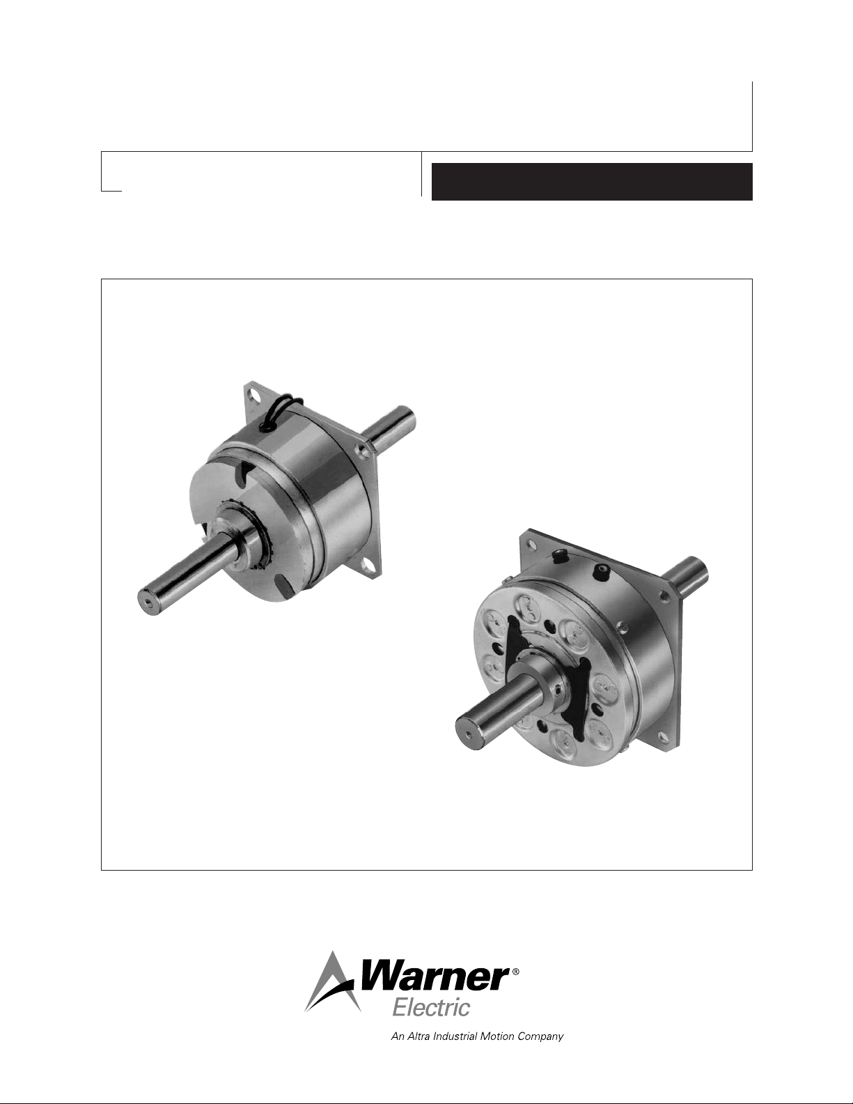
Primary Brakes
PB-120, PB-170, PB-250, PB-400
P-201
819-0480
Installation Instructions
Page 2
Contents
Mounting
Surface
Magnet
Pilot
Diameters
Installation Instructions
PB-120 PB-170 PB-250 PB-400 . . . . .2-9
Electrical Specifications . . . . . . . . . . . . . . . . . . . .5
Drawings and Parts Breakdown or Exploded Views
PB-120 . . . . . . . . . . . . . . . . . . . . . . . . . .10-11
PB-170 . . . . . . . . . . . . . . . . . . . . . . . . . .12-13
PB-250 . . . . . . . . . . . . . . . . . . . . . . . . . .14-15
PB-400 . . . . . . . . . . . . . . . . . . . . . . . . . .16-17
Warranty . . . . . . . . . . . . . . . . . . . . . . .Back Cover
Follow the installation instructions in this
manual carefully to ensure safe, reliable
operation. All stated or implied manufacturer
warranties are void if this product is not
installed in accordance with these
instructions.
Failure to follow these
instructions may result in product damage,
equipment damage, and serious or fatal injury
to personnel.
Primary Brake
PB-120 PB-170 PB-250 PB-400
The illustration drawings, parts lists, and
exploded views for these units can be found
beginning on page 10.
A. Installing the Conduit Box
To install the conduit box on the size 400 unit,
refer to the instructions supplied with conduit
box.
PB-170
PB-400
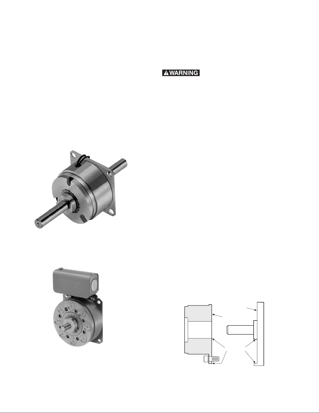
B. Mounting the Magnet
The brake magnet is mounted to a stationary
machine member by a flange. Extreme care
must be taken in selecting the location for the
mounting of the magnet. Proper positioning is
very important for the unit to function correctly.
1. A pilot diameter on the mounting surface is
essential to hold the magnet within the
required tolerances (Figure 1).
Figure 1
Warner Electric • 800-825-9050 P-201 • 819-0485
2
Page 3

Figure 2
2. A machined pilot diameter is provided on the
magnet mounting flange (refer to illustration
drawings page 10-17) to aid in the proper
positioning of the magnet.
Figure 3
3. An optional release spring may be used
with the standard armatures and hubs. The
release spring forces the armature back
against the hub retainer ring when the magnet
coil is de-energized.
3. Once the mounting surface has been
prepared, the magnet is bolted in place with
capscrews and lockwashers. (Figure 2.)
4. After assembly, the magnet must be
concentric and square within the required
tolerances listed on the illustration drawing.
C. Assembling the Armature and Hub
1. The antibacklash armatures are shipped
assembled and ready to be installed. See
Step D.
2. The standard armature and hub must be
assembled before it can be installed.
Assemble the armatures so that the shiny
surfaces (120 and 170) or backing plate sides
(250 and 400) are against the hub retainer
ring (Figure 3).
Follow these instructions to assemble the
armature and hub when the optional release
springs are being used.
Warner Electric • 800-825-9050 P-201 • 819-0485
3
Page 4
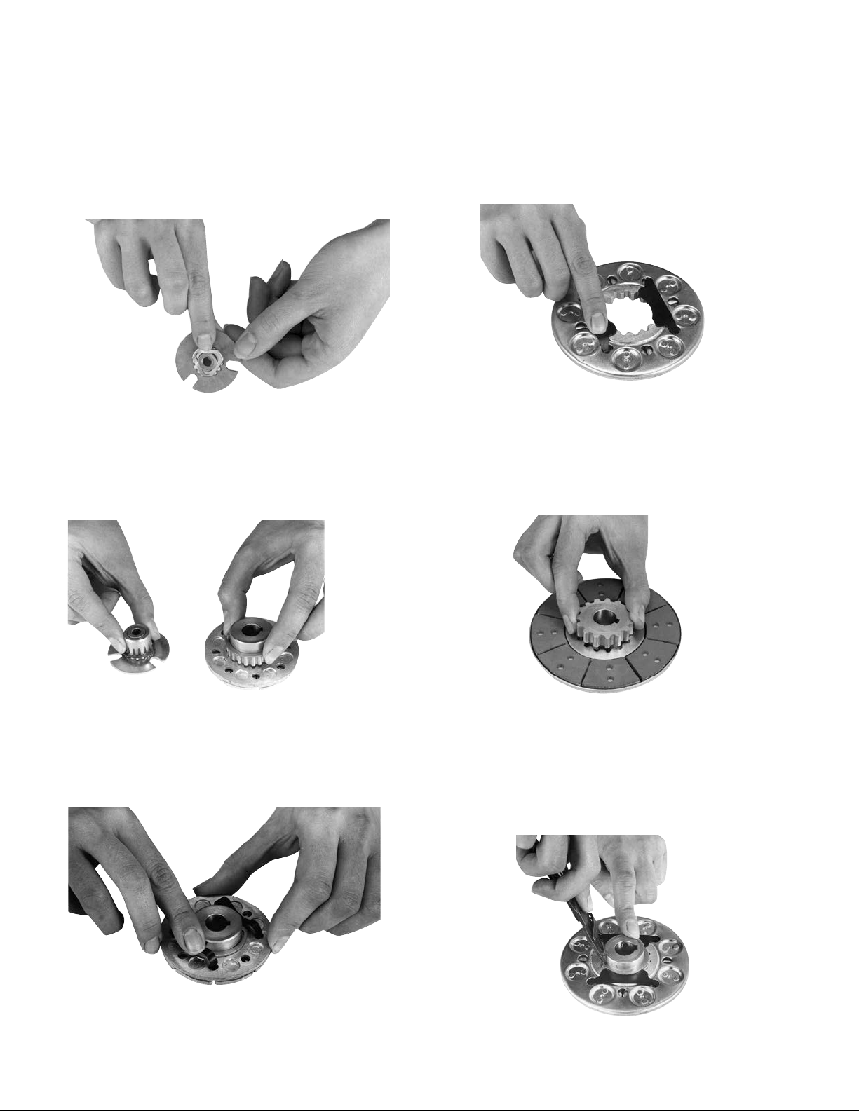
PB-170
Assemble the splined armature to the hub. The
shiny side of the armature should be against the
hub retainer ring.
Assemble the release spring into the groove in the
hub spline. The curved portion of the spring should
be against the armature. (Figure 4)
Figure 4
PB-250
Insert the hub, with snap ring intact, into the armature from the backing plate side. (Figure 5)
PB-400
Insert the release springs into the backing plate
holes of the armature. Bow the springs as
necessary to insert them into the armature.
(Figure 7)
Figure 7
Remove the snap ring from the hub.
Insert the hub, with the setscrew end first, into the
armature from the segmented side. Slide the hub
Figure 5
Insert both release springs into the holes of the
backing plate. Bow the springs as necessary to
into the armature until the release springs engage
the snap ring groove. (Figure 8)
Figure 8
insert them into the armature. (Figure 6)
Figure 6
Figure 9
Warner Electric • 800-825-9050 P-201 • 819-0485
4
Page 5

Assemble the snap ring into the groove in the
hub, clamping the release spring against the end
of the spline. (Figure 9)
4. Secure the assembly in this position by
alternately tightening the two setscrews in the
hub.
D. Mounting the Armature Assembly
5. The hub will need to be repositioned as wear
1. (250 and 400 units only) Insert a key in the
occurs with time.
keyway of the shaft.
2. Slide the armature assembly onto the shaft.
3. Position the assembly in accordance with
the overall axial dimensions given on the
illustration drawings. For air gap (.015'').
Electrical Specifications
Unit Size PB 120 PB 170
Voltage – DC 6 24 90 6 24 90
Resistance @ 20°C — Ohms 6.32 104 1386 6.96 111.2 1506
Current — Amperes .949 .230 .065 .861 .215 .060
Watts 5.69 5.52 5.85 5.85 5.16 5.37
Coil Build-up — Milliseconds 12 12 11 17 17 16
Coil Decay — Milliseconds 88 78 76
Unit Size PB 250 PB 400
Voltage – DC 6 24 90 6 24 90
Resistance @ 20°C — Ohms 5 76.4 1079 4.88 73 1087
Current — Amperes 1.2 .314 .084 1.23 .322 .083
Watts 7.2 7.5 7.51 7.39 7.96 7.45
Coil Build-up — Milliseconds 48 48 44 154 154 154
Coil Decay — Milliseconds 15 15 13 62 60 55
Notes: Build-up time equals current to approximately 90% of steady state value and flux to 90%.
Decay time equals current to approximately 10% of steady state value and flux to 10%.
Warner Electric • 800-825-9050 P-201 • 819-0485
5
Page 6
4
10
8
11
9-1
*7
3
6
5
9
9-1
12
2
1
4
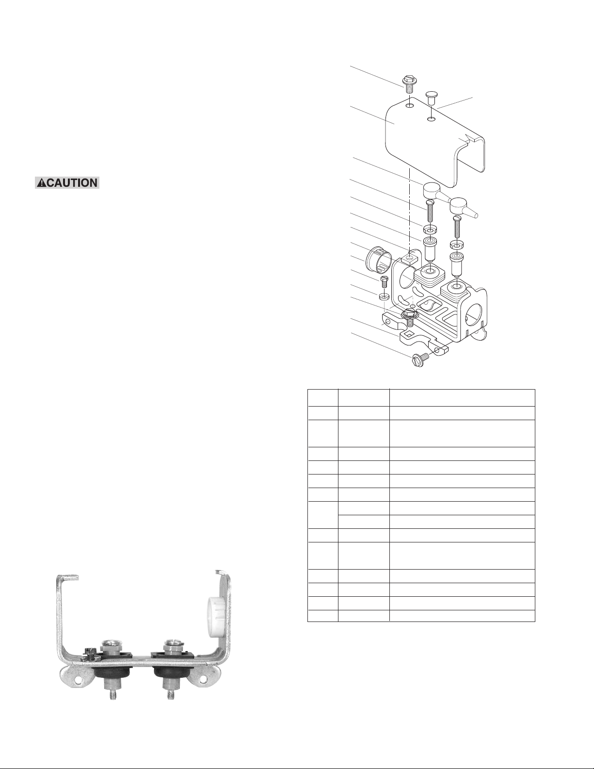
Installation Instructions
Conduit box kit No. 5200-101-010 contains all
components needed to assemble a conduit box for
PB400 brake.
When properly installed, this conduit box is
designed to provide a proper means for field wiring
terminations. It conforms to the requirements of
Underwriters Laboratories.
Do not connect rigid conduit
directly to the conduit box. A minimum of 12”
of flexible liquid tight conduit or other suitable
flexible wiring with appropriate fittings is
required. Flexible wiring is required to
prevent side loading of bearing on bearing
mounted clutches and possible deformation
or breakage of the conduit box or
clutch/brake components during assembly.
Step 1
Assemble a customer supplied flexible wiring
connector into desired end of conduit box (3).
Press protective plug (5) into unused conduit hole.
Components
Thread green washer head hex screw (9) into
round hole in base of conduit box. Place terminal
ring (9-1) over screw before inserting.
Snap two wire grommets (6) into square holes in
conduit box base. The grommet crowns should
be toward the outside of the box and the rubber
flanges should be on both sides of the conduit
box.
Push two terminal spacers (7) through rubber
grommets. Number 6 spacers fit in PB400. (See
Figure 10)
Parts List for kit 5200-101-010
Item Quantity Part Name
11Bracket
-21
31Box, Conduit
43Screw, Hex, Washer Head
51Plug, Protective
62Grommet, Wire
*7
2 Spacer No. 8 Thd.
2 Spacer No. 6 Thd.
82Cap terminal
91
Screw, Hex, Washer Head
and Sems Conical Washer
Screw, Hex, Washer Head,
Green
9-1 3 Terminal, Ring
10 1 Cover
11 2 Screw, No. 8 Brass
12 1 Plug, Protective
*The No. 6 spacers are required on Sizes 375, 400 and 475. All
others use No. 8.
Warner Electric • 800-825-9050 P-201 • 819-0485
6
Figure 10
Page 7
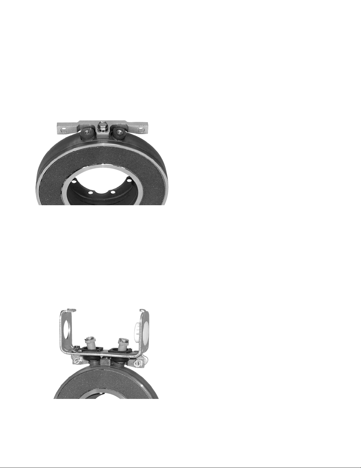
Step 2
Fasten bracket (1) to clutch field/brake magnet
with one No. 10-32 hex washer head screw (2).
The screw is self-tapping, threads are not
provided in the magnet bracket adapter. The
square projection on the magnet fits into the
square hole in the bracket. The curved side of
the bracket mounts toward the magnet. The
bracket flange is toward the flange side of the
magnet. (See Figure 11)
Step 4
Connect electric supply cable to the fitting
installed on the conduit box. If an external power
supply is furnishing DC current to the clutch or
brake, proceed to Step 5 and skip Step 6. If a
Warner Electric CBC-100 power supply is being
installed in the conduit box, skip Step 5 and
proceed to Step 6.
Step 5 - DC Connection
Slide one terminal cap (8) onto each of the two
supply conductors, small end first. Connect the
two supply conductors (with rubber caps) to the
magnet or field terminals using two No. 8 brass
screws (11) and ring terminals (9-1). The
stripped wires can wrap around the screw
between the terminal ring and the screw head
or other ring type terminals may be used.
Electrical supply connections must confirm to
local electrical codes. Install plug (12) into cover
hole.
Figure 11
Step 3
Mount conduit box to bracket. The conduit box
flange must be toward flange side or the magnet
(rear of bracket). Thread terminal spacers into
field/magnet before fastening conduit box to
bracket. Do not over tighten, excessive torque
will pull thread insert out of magnet/field. Secure
conduit box to bracket with two No. 10-32 hex
washer head screws (4). (See Figure 12)
Figure 12
Step 6 - AC Connection
When a CBC-100 power supply is used, refer
to installation sheet P-266 provided with the
CBC-100, following instructions carefully. To
mount the CBC-100 to the conduit box, place
the control into the cover so the curved surfaces
conform, line up the cover hole with the control
mounting hole and fasten with screw provided in
the mounting kit. Connections to the magnet or
field terminals are as outlined in Step 5.
Step 7
A ground wire is recommended for grounding of
the conduit box and brake magnet or clutch
field. Connect this wire with the green ground
screw (9) to the hole in the bottom of the box.
Consult electrical local codes regarding
grounding requirements.
Step 8
Install cover (10) by sliding the slot in the cover
over the tab on one end of the conduit box and
secure the cover on the opposite end with one
No. 10-32 hex washer head screw (11).
Warner Electric • 800-825-9050 P-201 • 819-0485
7
Page 8

Burnishing and Maintenance
Burnishing
Intimate metal to metal contact is essential
between the armature and the metal rings (poles)
of the magnet or rotor. Warner Electric clutches
and brakes leave the factory with the friction
material slightly undercut to assure good initial
contact.
Normally, the desired wearing-in process occurs
naturally as the surfaces slip upon engagement.
The time for wear-in, which is necessary to
obtain the ultimate torque of the unit, will vary
depending on speed, load, or cycle duty.
If maximum torque is required immediately after
installation, the unit should be burnished by
slipping the friction surfaces together at reduced
voltage. It is recommended that the burnishings
be done right on the application, if at all possible.
Maintenance
Wear Pattern: Wear grooves appear on the
armature and magnet surfaces. This is a normal
wear condition, and does not impair functioning
of the unit. Normally, the magnet and armature,
as a mating pair, will wear at the same rate. It is
the usual recommendation that both components be replaced at the same time.
Remachining the face of a worn armature is not
recommended. If a replacement armature is to
be used with a used magnet, it is necessary to
remachine the worn magnet face. In refacing a
magnet: (1) machine only enough material to
clean up the complete face of the magnet; (2)
hold the face within .005" of parallel with the
mounting plate; and (3) undercut the molded
facing material .001" - .003" below the metal
poles.
Burnishing at high speed will result in a
smoother wear-in pattern and reduce the time
for burnishing. The voltage should be set at
approximately 30% or 40% of the rated value.
The unit should be cycled on and off to allow
sufficient time between slip cycles to prevent
overheating.
When a Warner Electric brake or clutch is
properly assembled and installed, no further
servicing, lubrication, or maintenance should be
required throughout the life of the unit.
Heat: Excessive heat and high operating
temperatures are causes of rapid wear. Units,
therefore, should be ventilated as efficiently as
possible, especially if the application requires
fast, repetitive cycle operation.
Foreign Materials: If units are used on
machinery where fine, abrasive dust, chips or
grit are dispelled into the atmosphere, shielding
of the brake may be necessary if maximum life
is to be obtained.
Where units are used near gear boxes or
transmissions requiring frequent lubrication,
means should be provided to protect the friction
surfaces from oil and grease to prevent serious
loss of torque.
Oil and grease accidentally reaching the friction
surfaces may be removed by wiping with a rag
dampened with a suitable cleaner, which leaves
no residue. In performing this operation, do not
drench the friction material.
Warner Electric • 800-825-9050 P-201 • 819-0485
8
Page 9

If the friction materials have been saturated
with oil or grease, no amount of cleaning will be
completely effective. Once such a unit has been
placed back in service, heat will cause the oil to
boil to the surface, resulting in further torque
loss.
Torque Loss: If a brake or clutch slips or loses
torque completely, the initial check should be
the input voltage to the magnet as follows:
90-Volt Series: Connect a DC voltmeter with
a range of 0-100 or more directly across the
magnet terminals. With the power on and the
potentiometer turned up, a normal reading is 90
volts, although 85 to 95 is satisfactory. The
reading should drop as the potentiometer
control is adjusted counterclockwise.
24-Volt Series: Use a DC voltmeter with a
range of 0-30 volts or more. A normal reading
is approximately 22-26 volts.
this manual. A very high or infinite resistance
reading would indicate an open coil.
If the above checks indicate that the proper
voltage and current is being supplied to the
magnet, mechanical parts should be checked to
assure that they are in good operating condition
and properly installed.
6-Volt Series: Use a DC voltmeter of
approximately 0-15 volt range. A normal reading
is from 5.5 to 6.5 volts.
The above checks normally are sufficient.
Further checks may be made as follows:
Connect a low range ammeter in series with
one magnet lead. Correct amperage readings
for each coil voltage and unit size are found on
page 5 of this manual.
These readings are with the power on and
condition control in the maximum output voltage.
Ohmmeter checks should be made with the
power off and the circuit open (to be certain,
disconnect one lead to the magnet). Average
resistance readings are also listed on page 5 of
Warner Electric • 800-825-9050 P-201 • 819-0485
9
Page 10

PB-120 Brake
For Bore sizes
see chart below.
Std. Armature
Antibacklash
Armature
Armature View
1.499/1.497 Pilot Diameter
.015 When New
.072 (Std.)
.072 (Anti.)
.109 (Std.)
.140 (Anti.)
.500
1.234
Max.
Dia.
.562
Std. Arm.
Anti Arm.
.343
12
.072 (Std.)
.072 (Anti.)
.015
.625
.312
.062
.375 Dia.
#4-40
UNC-3A
.187
Max.
45°
.130/.123 dia. (4)
holes equally spaced
on 1.312 diameter*
1.125 Max. Sq.
Magnet View
*Mounting holes are within .006 of true position relative to pilot diameter.
Customer Shall Maintain:
1. Concentricity of brake mounting pilot diameter
with armature shaft within .003 T.I.R.
2. Squareness of brake mounting face with
armature shaft within .003 T.I.R.
.968 Max.
Bore Dimensions
Armature
Bore Dia.
.188/.187
.251/.250
(.313/.312)*
*(Antibacklash Armatures)
Shaft Sizes .187 – .250
Static Torque 5 lb. in.
Maximum Speed 10,000 rpm
Standard Voltage D.C. 6, 24, 90
Warner Electric • 800-825-9050 P-201 • 819-0485
10
Page 11

1B
3
2
1A
1A-1
1A-2
PB-120 Brake Drawing I-25507
Item Description Part Number Qty.
1A Armature and Hub
1A-1 Armature Hub 1
3/16" Bore 5622-541-009
1/4" Bore 5622-541-008
1A-2 Armature 110-0110 1
1B Antibacklash Armature 1
3/16" Bore 5622-111-004
1/4" Bore 5622-111-002
5/16" Bore 5622-111-003
2 Mounting Accessory 5101-101-001 1
3 Magnet 1
6 Volt 5373-631-003
24 Volt 5373-631-005
90 Volt 5373-631-007
How to Order:
1. Specify Type of Armature Desired.
2. Specify Bore Size for Item 1A-1 or 1B.
3. Specify Voltage for Item 3.
Example:
PB-120 Brake per I-25507 - 90 Volt, Standard
Armature 3/16" Hub Bore
These units meet the standards of UL508 and are
listed under guide card #NMTR, file #59164.
These units are CSA certified under file #LR11543.
Warner Electric • 800-825-9050 P-201 • 819-0485
11
Page 12

PB-170 Brake
For Bore sizes
see chart below.
Std. Armature
Antibacklash
Armature
Armature View
2.437/2.435 Pilot Diameter
1.718
Max.
Dia.
.015 When New
.086 (Std.)
.094 (Anti.)
.125 (Std.)
.109 (Anti.)
.625
Std.
Arm.
.843
Anti.
Arm.
12
Min.
.390
.062
.752/.750
Pilot Dia.
#8-32
UNC-3A
45°
.204/.187 dia. (4)
holes equally spaced
on 2.125 diameter*
1.812 Max. Sq.
Magnet View
*Mounting holes are within .010 of true position relative to pilot
diameter.
Customer Shall Maintain:
1. Squareness of brake mounting face with
armature shaft within .006 T.I.R.
2. Concentricity of brake mounting pilot diameter
with armature shaft within .010 T.I.R.
.015
.086 (Std.)
.515
.094 (Anti.)
.812
1.375 Max.
Bore Dimensions
Armature
Bore Dia.
.251/.250
.313/.312
.376/.375
Shaft Sizes .250 – .375
Static Torque 15 lb. in.
Maximum Speed 10,000 rpm
Standard Voltage D.C. 6, 24, 90
.437
Max.
Warner Electric • 800-825-9050 P-201 • 819-0485
12
Page 13

PB-170 Brake Drawing I-25753
3
1A-3
2
1B
1A-1
1A-2
1A
Item Description Part Number Qty.
1A Armature and Hub
1A-1 Armature Hub 1
1A-2 Armature 110-0111 1
1A-3 Release Spring 808-0019 1
1B Antibacklash Armature 1
2 Mounting Accessory 5102-101-001 1
3 Magnet 1
1/4" Bore 5102-541-002
5/16" Bore 5102-541-003
3/8" Bore 5102-541-004
1/4" Bore 5623-111-008
5/16" Bore 5623-111-009
3/8" Bore 5623-111-010
6 Volt 5375-631-003
24 Volt 5375-631-005
90 Volt 5375-631-007
Warner Electric • 800-825-9050 P-201 • 819-0485
How to Order:
1. Specify Type of Armature Desired.
2. Specify Bore Size for Item 1A-1 or 1B.
3. Specify Voltage for Item 3.
Example:
PB-170 Brake per I-25753 - 90 Volt, Antibacklash
Armature, 1/4" Armature Hub Bore
These units meet the standards of UL508 and are
listed under guide card #NMTR2, file #59164.
These units are CSA certified under file #LR11543.
13
Page 14

PB-250 Flange Mounted Brake
For Bore & Keyway
sizes see chart below.
Std. Armature
Antibacklash
Armature
.437
Max.
Armature View
24°
12°
.437 Max.
2.625
Max.
Dia.
.343 Max.
.015 When New
.171 (Std.)
.187 (Anti.)
1.187
Std. Arm.
1.390
Anti. Arm.
.203 Min.
.687 (Std.)
.718 (Anti.)
1.250
1.078
.718
K
.015
.062
1.968 (Std.)
1.984 (Anti.)
1.063
1.061
Pilot Dia.
#8-32
UNC-3A
.437
Max.
2.625 Sq.
45°
3.500/3.498 Pilot
Diameter
.204/1.87 diameter (4) holes equally
spaced on 3.125 diameter
Field View
*Mounting holes are within .010 of true position relative to pilot
diameter.
Customer Shall Maintain:
1. Squareness of brake mounting face with
armature hub shaft within .006 T.I.R.
2. Concentricity of brake mounting pilot
diameter with armature shaft within .010 T.I.R.
Bore and Keyway Dimensions
Armature
Bore Dia. Keyway
.376/.375 .093 x .046
*.438/.437
.501/.500 .125 x .062
*.563/.562
.626/.625
*.688/.687 .187 x .093
.751/.750
* Available on special order only.
Shaft Sizes .375 – .750
Static Torque 70 lb. in.
Maximum Speed 7,500 rpm
Standard Voltage D.C. 6, 24, 90
Warner Electric • 800-825-9050 P-201 • 819-0485
14
Page 15

PB-250 Flange Mounted Brake Drawing I-25519
1A
1A-3
1A-2
1A-1
2
3
1B
2-1
Item Description Part Number Qty.
1A Armature and Hub
1A-1 Armature Hub 1
1A-2 Release Spring 5103-101-003 1
1A-3 Armature 5124-111-001 1
1B Antibacklash Armature 1
2 Magnet 1
2-1 Terminal Accessory 5103-101-002 1
3 Mounting Accessory 5102-101-001 1
3/8" Bore 5103-541-002
1/2" Bore 5103-541-004
5/8" Bore 5103-541-006
3/4" Bore 5103-541-008
3/8" Bore 5365-111-003
1/2" Bore 5365-111-005
5/8" Bore 5365-111-007
3/4" Bore 5365-111-009
6 Volt 5319-631-002
24 Volt 5319-631-003
90 Volt 5319-631-005
How to Order:
1. Specify Type of Armature Desired.
2. Specify Bore Size for Item 1A-1 and 1B.
3. Specify Voltage for Item 2.
Example:
PB-250 Brake per I-25519 – 90 volt, Standard
Armature, 1/2'' Armature Hub Bore.
These units meet the standards of UL508 and are
listed under guide card #NMTR2, file #59164.
These units are CSA certified under file #LR11543.
Warner Electric • 800-825-9050 P-201 • 819-0485
15
Page 16

PB-400 Flange Mounted Brake
For Bore & Keyway sizes
see chart below.
Std. Armature
Antibacklash
Armature
Removable plug in
ends for 1/2" con-
duit.
Armature View
3.750
Std. Arm.
Anti. Arm.
.015 When New
.328 Max.
1.250
4.234
Max.
Dia.
1.640
1.546
.953
3.562
Pilot Dia.
1/4-20
UNC-3A
1.875
1.873
4.687 Max.
45°
5.625/5.623
Pilot diameter
.296/.280 diameter (4) holes equally
spaced on 5.000 diameter
Field View
*Mounting holes are within .010 of true position relative to pilot diameter.
Customer Shall Maintain:
1. Squareness of brake mounting face with
armature hub shaft within .006 T.I.R.
2. Concentricity of brake mounting pilot
diameter with armature shaft within .010 T.I.R.
4.250
Sq.
.187 (Std.)
.218 (Anti.)
.343
.875 (Std.)
.843 (Anti.)
.015
.093
1.312
1.500
2.328 (Std.)
2.359 (Anti.)
Bore and Keyway Dimensions
Armature
Bore Dia. Keyway
.501/.500 .125 x .062
*.563/.562
.626/.625
*.688/.687
.751/.750 .187 x .093
.876/.875
* Available on special order only.
Shaft Sizes .500 – .875
Static Torque 270 lb. in.
Maximum Speed 4,500 rpm
Standard Voltage D.C. 6, 24, 90
.609 Max.
Warner Electric • 800-825-9050 P-201 • 819-0485
16
Page 17

PB-400 Flange Mounted Brake Drawing I-25694
3
2
4
2-1
1A-2
1A-3
1A
1B
1A-1
Item Description Part Number Qty.
1A Armature and Hub
1A-1 Armature Hub 1
1/2" Bore 5104-541-002
5/8" Bore 5104-541-004
3/4" Bore 5104-541-006
7/8" Bore 5104-541-007
1A-2 Armature 5125-111-001 1
1A-3 Release Spring 5104-101-003 1
1B Antibacklash Armature 1
1/2" Bore 5367-111-003
5/8" Bore 5367-111-005
3/4" Bore 5367-111-007
7/8" Bore 5367-111-008
2 Magnet 1
2-1 Terminal Accessory 5103-101-002 1
3 Conduit Box 5200-101-010 1
4 Mounting Accessory 5104-101-002 1
6 Volt 5115-631-002
24 Volt 5115-631-003
90 Volt 5115-631-004
How to Order:
1. Specify Type of Armature Desired.
2. Specify Bore Size for Item 1A-1 or 1B.
3. Specify Voltage for Item 2.
Example:
PB-400 Brake per I-25694 - 90 Volt, Antibacklash
Armature, 3/4" Armature Hub Bore
These units meet standards set forth in UL508 and
are listed under guide card #NMTR, file #59164.
These units are CSA certified under file #LR11543.
Warner Electric • 800-825-9050 P-201 • 819-0485
17
Page 18

Warranty
Warner Electric LLC warrants that it will repair or replace (whichever it deems advisable) any
product manufactured and sold by it which proves to be defective in material or workmanship within a
period of one (1) year from the date of original purchase for consumer, commercial or industrial use.
This warranty extends only to the original purchaser and is not transferable or assignable without
Warner Electric LLC’s prior consent.
Warranty service can be obtained in the U.S.A. by returning any defective product, transportation
charges prepaid, to the appropriate Warner Electric LLC factory. Additional warranty information may
be obtained by writing the Customer Satisfaction Department, Warner Electric LLC, 449 Gardner
Street, South Beloit, Illinois 61080, or by calling 815-389-3771.
A purchase receipt or other proof of original purchase will be required before warranty service is
rendered. If found defective under the terms of this warranty, repair or replacement will be made,
without charge, together with a refund for transportation costs. If found not to be defective, you will be
notified and, with your consent, the item will be repaired or replaced and returned to you at your
expense.
This warranty covers normal use and does not cover damage or defect which results from
alteration, accident, neglect, or improper installation, operation, or maintenance.
Some states do not allow limitation on how long an implied warranty lasts, so the above limitation may
not apply to you.
Warner Electric LLC’s obligation under this warranty is limited to the repair or replacement of the
defective product and in no event shall Warner Electric LLC be liable for consequential, indirect,
or incidental damages of any kind incurred by reason of the manufacture, sale or use of any defective
product. Warner Electric LLC neither assumes nor authorizes any other person to give any other
warranty or to assume any other obligation or liability on its behalf.
WITH RESPECT TO CONSUMER USE OF THE PRODUCT, ANY IMPLIED WARRANTIES WHICH THE
CONSUMER MAY HAVE ARE LIMITED IN DURATION TO ONE YEAR FROM THE DATE OF ORIGINAL
CONSUMER PURCHASE. WITH RESPECT TO COMMERCIAL AND INDUSTRIAL USES OF THE
PRODUCT, THE FOREGOING WARRANTY IS IN LIEU OF AND EXCLUDES ALL OTHER
WARRANTIES, WHETHER EXPRESSED OR IMPLIED BY OPERATION OF LAW OR
OTHERWISE, INCLUDING, BUT NOT LIMITED TO, ANY IMPLIED WARRANTIES OF
MERCHANTABILITY OR FITNESS.
Some states do not allow the exclusion or limitation of incidental or consequential damages, so the
above limitation or exclusion may not apply to you. This warranty gives you specific legal rights and
you may also have other rights which vary from state to state.
Changes in Dimensions and Specifications
All dimensions and specifications shown in Warner Electric catalogs are subject to change without
notice. Weights do not include weight of boxing for shipment. Certified prints will be furnished without
charge on request to Warner Electric.
Warner Electric LLC
31 Industrial Park Road
815-389-3771
www.warnerelectric.com
An Altra Industrial Motion Company
P-201 819-0485 06/11 Printed in USA
• Fax: 815-389-2582
• New Hartford, CT 06057
 Loading...