

Page 1
P-2085-WE
SM318-gb-02/09
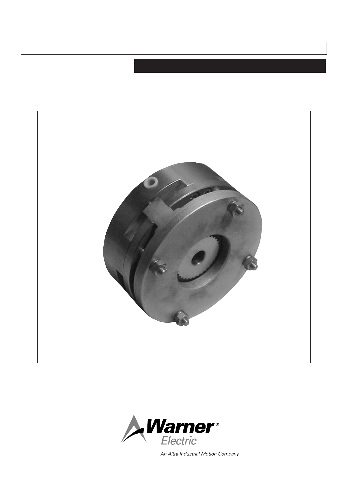
Pneumatic Single Disc
and Dual Disc Brakes
P250 and P620
Service Manual
Page 2
We, WARNER ELECTRIC EUROPE, 7, rue Champfleur, B.P. 20095, F-49182 St Barthélemy d’Anjou Cedex
declare that the brakes made in our factories from St Barthélemy d’Anjou,
and hereafter designated : P520 and P620
are exclusively designed for incorporation into a machine and to be assembled with other equipments to create a machine. The operation of
the product is submitted to the conformity of the complete equipment, following the provisions of the machinery directive 98/37/EC.
Drawn up in St Barthélemy d’Anjou, July 2002
E. PRAT, General Managing Director
CONTENTS
1 Technical specifications 2
2 Precautions and restrictions on use 2
2.1 Restrictions on use 2
2.2 Precautions and safety measures 3
3 Installation 3
3.1 Transport - storage 3
3.2 Handling 3
3.3 Installing 3
1 Technical specifications
P520 VAR00 - single disc brakes 10 20 50 100 200 400 800 1600
Size
Max. Speed min -1
P brake release bar
P max. bar
Nominal travel “T” mm
Tolerance on travel mm
Max. Travel mm
Tightening Torque (909) (±10%)
Nm
Weight kg
10
6800
6
7
0,2
+0,1/0
0,8
6
2,1
P620 VAR00 - dual disc brakes 50 100 200 400 800 1600 3200
Size
Max. Speed min -1
P brake release bar
P max. bar
Nominal travel “T” mm
Tolerance on travel mm
Max. Travel mm
Tightening Torque (909) (±10%)
Nm
Weight kg
50
5000
6
7
0,3
+0,2/0
1,2
6
4,9
4 Maintenance 4
4.1 Adjusting travel 4
4.2 Maintenance 4
4.3 Spare parts 4
5 Pneumatic connection 4
5.1 Recommendations 4
5.2 Connection diagram 4
6 Appendix 5
20
5000
6
7
0,2
+0,1/0
1,2
6
4,2
100
4150
0,4
+0,2/0
1,2
13
9,7
6
7
50
4150
6
7
0,3
+0,1/0
1,2
13
8,5
200
3200
+0,2/0
17,5
6
7
0,4
1,5
13
100
3200
6
7
0,3
+0,1/0
1,5
13
15,5
+0,2/0
400
2600
6
7
0,4
1,5
26
26,0
200
2600
6
7
0,3
+0,1/0
1,5
26
22,5
400
2200
5
6
0,4
+0,2/0
1,8
48
36,0
800
2200
5
6
0,5
+0,2/0
1,8
48
41,0
800
1700
5
6
0,4
+0,2/0
1,8
76
58
1600
1700
5
6
0,5
+0,3/0
1,8
76
68,0
1600
1500
5
6
0,5
+0,2/0
2
189
110
3200
1500
5
6
0,6
+0,3/0
2
189
130,0
Table 1
NB: Data for catalogue equipment.
2 Precautions and restrictions on use
2.1 Restrictions on use
Exceeding the maximum rotation speeds stated
in the catalogue invalidates the warranty.
The equipment is designed to operate dry. Any
oily material will alter its performance.
Theses brakes are designed solely for horizontal
axis operation..
2 Warner Electric Europe • +33 (0)2 41 21 24 24 P-2085-WE • 11/12
Page 3

Symbol designating an action that
might damage the apparatus
Symbol designating an action that
might be dangerous to human safety
2.2 Precautions in use and safety measures
During maintenance, ensure that the machine’s
moving parts are stationary and that there is no
risk of accidental start-up. All intervention have
to be made by qualified personnel, owning this
manual.
Any modification made to the brake without
the express authorisation of a representative of
Warner Electric, in the same way than any use
out of the contrac tual specifications accepted by
“Warner Electric”, will result in the warranty being
invalidated and Warner Electric will no longer be
liable in any way with regard to conformity.
3 Installation
3.1 Transport / storage
Our brakes are supplied in packaging
guaranteeing a preservation period of 6 months
with land or air transport, or after transport by
ship to neighbouring continents (without crossing
the tropics).
3.2 Handling
Avoid any impacts on the equipment so as not to
alter their performance.
Never carry the equipment by the electrical
supply cable.
3.3 Installing
For installation on the support or frame, it is
essen tial to proceed as follows, (see appendix).
• Compress the springs by putting the chamber
under pressure (see chapter 5), the moving
armature (330) should be in contact with the
cylinder (401)
Disc with collar
(Size 400)
Disc with collar
(Size 800)
P520 P620
Fig. 1
Fig. 2
The hub is normally supplied to tolerance H7
on the bore and P9 on the width of the key-way
(In accordance with NF E 22-175/ DIN6885/BS
4235/ISO R773).
• Locate the friction plate (348) on the support.
Then fit the friction disc (312) and in the case
of a dual disc brake (P620), the intermediate
disc (320) then the second friction disc (312)
NB: The collar on friction discs must face the
friction plate (See figure 1).
• Put the moving armature assembly (330) /
cylinder / piston (401/402) between the lugs of
the friction plate (312) then fix the assembly by
means of the bolts (909) and washers carefully
tightening to the correct torque (see table1)
• Put the equipment under pressure (see chapter
5) and check that the disc rotates freely
• Remove the fixing bolts (909), the friction plate
(348), the friction disc(s) (312) and the interme
diate disc (320) in the case of dual disc brakes
• Slide the hub (515) onto the shaft to be braked,
adjust the drive key and stop it axially by the
• Make several movements, motor stopped, and
check the value of the nominal airgap (see table
1) near the friction plate lugs (348)
• In the event of insufficient travel, refer to
chapter 4 (maintenance)
means provided
Do not oil the guide splines (friction disc / hub) or
performance will be affected.
WARNING: It is essential that the hub is assem-
bled in the right way round (See fig 1 above)
Warner Electric Europe • +33 (0)2 41 21 24 24 P-2085-WE • 11/12 3
Page 4

4 Maintenance
12534
5 Pneumatic connection
4.1 Adjusting travel
To modify the travel “T” (see appendix), undo
the fixing bolt (909) about one turn, then set the
adjustment bolt (902) to the value necessary.
Lock the fixing bolts (909) to the correct torque
(see table 1). Check the value of the travel at
several points near the friction plate legs (348).
4.2 Maintenance
Wear in the linings causes an increase in the
travel. Before reaching maximum value (see
table 1), it is necessary to make an adjustment
(See above). Make several movements, motor
stopped, check the new value for the travel at
several points as described above.
4.3 Spare parts
After a number of adjustments, variable
depending on the size of the machinery and its
use, replacement of the fric tion disc or discs is
necessary when the value “ Y” for the interval
between the friction plate lugs (312) and the
cylin der (401) reaches the value in the table
below. To replace them, refer to paragraph 3-3.
A new adjustment of the travel is necessary
(see paragraph 4.1).
5.1 Recommendations
The equipment must be supplied with filtered,
oiled compressed air.
Comply with the specified control pressure
(table 1) so as to ensure correct brake release
on the equipment.
5.2 Connection diagram
This functional diagram is given as an indication:
12534
Key:
1. Pressure source
2. Treatment unit consisting of: filter, pressure relief
and oiler simplified symbol)
3. Manual, mechanical, electrical or pneumatic control
3/2 distributor
4. Flexi pipe
5. Equipment to be controlled
Y
Fig. 3
P520 10 20 50 100 200 400 800 1600
Y min. mm
P620 50 100 200 400 800 1600 3200
Y min. mm
Important: Before refitting the cylinder onto the piston,
lightly lubricate the seals and contact surfaces with a
film of Molykote 55M or equivalent grease.
Take care not to damage the seals while re-
assem bling.
0 0 0 0 0 2
0 0 0 0 3
4 Warner Electric Europe • +33 (0)2 41 21 24 24 P-2085-WE • 11/12
Page 5

6 Appendix
51
34
P520
P620
312 701
5
8
T
740330902
909
702
901
402
401
515
312
320 701 401
T
330348 740
909
402
901
702
902
Nr Appendix
312
320
330
348
401
402
515
701
702
740
901
902
909
Friction disc
Intermediate disc
Moving armature
Friction plate
Cylinder
Piston
Hub
Piston O-ring
Cylinder O-ring
Spring
Screw
Adjustment screw
Fixating screw
Warner Electric Europe • +33 (0)2 41 21 24 24 P-2085-WE • 11/12 5
Page 6

Warranty
Warner Electric LLC warrants that it will repair or replace (whichever it deems advisable) any product manufactured and
sold by it which proves to be defective in material or workmanship within a period of one (1) year from the date of original
purchase for consumer, commercial or industrial use.
This warranty extends only to the original purchaser and is not transferable or assignable without Warner Electric LLC’s
prior consent.
Warranty service can be obtained in the U.S.A. by returning any defective product, transportation charges prepaid, to
the appropriate Warner Electric LLC factory. Additional warranty information may be obtained by writing the Customer
Satisfaction Department, Warner Electric LLC, 449 Gardner Street, South Beloit, Illinois 61080, or by calling 815-389-
3771.
A purchase receipt or other proof of original purchase will be required before warranty service is rendered. If found
defective under the terms of this warranty, repair or replacement will be made, without charge, together with a refund for
transportation costs. If found not to be defective, you will be notified and, with your consent, the item will be repaired or
replaced and returned to you at your expense.
This warranty covers normal use and does not cover damage or defect which results from alteration, accident, neglect, or
improper installation, operation, or maintenance.
Some states do not allow limitation on how long an implied warranty lasts, so the above limitation may not apply to you.
Warner Electric LLC’s obligation under this warranty is limited to the repair or replacement of the defective product and
in no event shall Warner Electric LLC be liable for consequential, indirect, or incidental damages of any kind incurred by
reason of the manufacture, sale or use of any defective product. Warner Electric LLC neither assumes nor authorizes any
other person to give any other warranty or to assume any other obligation or liability on its behalf.
WITH RESPECT TO CONSUMER USE OF THE PRODUCT, ANY IMPLIED WARRANTIES WHICH THE CONSUMER MAY
HAVE ARE LIMITED IN DURATION TO ONE YEAR FROM THE DATE OF ORIGINAL CONSUMER PURCHASE. WITH
RESPECT TO COMMERCIAL AND INDUSTRIAL USES OF THE PRODUCT, THE FOREGOING WARRANTY IS IN LIEU
OF AND EXCLUDES ALL OTHER WARRANTIES, WHETHER EXPRESSED OR IMPLIED BY OPERATION OF LAW OR
OTHERWISE, INCLUDING, BUT NOT LIMITED TO, ANY IMPLIED WARRANTIES OF MERCHANTABILITY OR FITNESS.
Some states do not allow the exclusion or limitation of incidental or consequential damages, so the above limitation or
exclusion may not apply to you. This warranty gives you specific legal rights and you may also have other rights which
vary from state to state.
Changes in Dimensions and Specications
All dimensions and specifications shown in Warner Electric catalogs are subject to change without notice. Weights do not
include weight of boxing for shipment. Certified prints will be furnished without charge on request to Warner Electric.
Warner Electric Europe
7 rue Champfleur, B.P. 20095, St Barthelemy d’Anjou - France
+33 (0)2 41 21 24 24 • Fax: +33 (0)2 41 21 24 70
www.warnerelectric.com
Printed in USAP-2085-WE • 11/12
 Loading...