

Page 1
Advanced Technology Tension
Clutches
P-220
819-0339
Installation Instructions
Page 2
Contents
Clutch Installation
Installation . . . . . . . . . . . . . . . . . . . . . . . . . . . . . . . . . 2
Clutch Repair – On the Shaft . . . . . . . . . . . . . . . . . . 4
Clutch Service – Major . . . . . . . . . . . . . . . . . . . . . . . 7
Troubleshooting. . . . . . . . . . . . . . . . . . . . . . . . . . . . 15
Dimensions . . . . . . . . . . . . . . . . . . . . . . . . . . . . . . . 16
Specifications . . . . . . . . . . . . . . . . . . . . . . . . . . . . . 16
Exploded View and Parts List. . . . . . . . . . . . . . . . . 18
Warranty . . . . . . . . . . . . . . . . . . . . . . . . . . Back Page
Failure to follow these
instructions may result in product damage, equipment damage, and serious or fatal injury to personnel.
The Warner Electric Advanced Technology Tension
(ATT) clutch you have purchased has been designed
to provide long and trouble-free service. It is a
rugged and durable unit that is rebuildable with both
friction face replacement and complete clutch rebuild
kits discussed in this service manual. The friction
face replacement kit renews the friction surfaces,
while the complete clutch rebuild kit includes new
bearings, components and hardware in addition to
the friction faces.
1. Remove your ATT Clutch from its shipping carton
and inspect it thoroughly to ensure that it has
arrived in good condition.
An accessory kit included with your clutch contains a key, retaining ring, and coil wire retainer.
In addition, you may have ordered the optional
sheave or timing belt pulley and field restraining
strap.
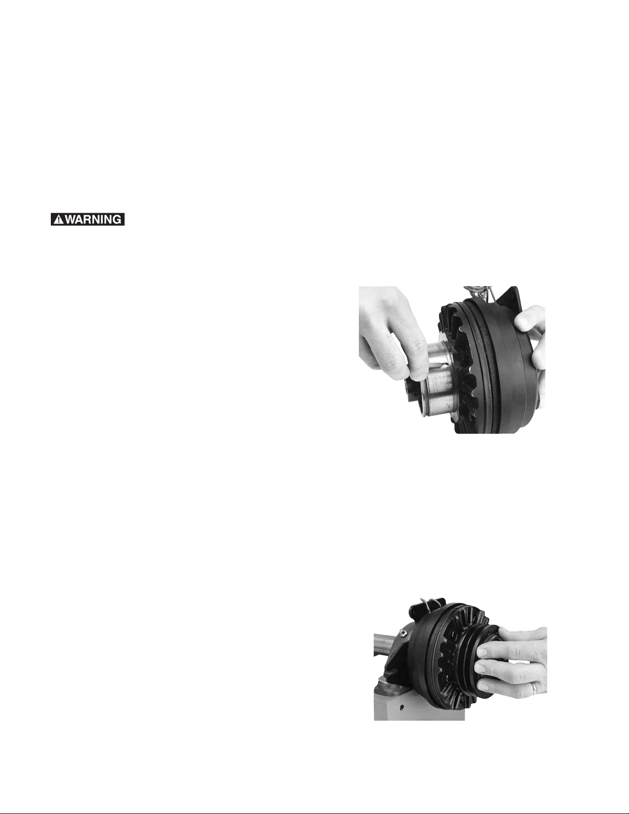
2. Install the factory-ordered sheave or pulley by
first inserting the key in its keyway. Place the
sheave or pulley so it will fit onto the hub, aligning the keyway with the key and keeping the
sheave tapped holes facing away from the
clutch. (See Figure 1)
This service manual includes instructions required for
installation, repair on the shaft, and major rebuilding,
as well as troubleshooting information, specifications,
dimensions, an exploded view and parts list. Please
refer to the Table of Contents above for the section
page numbers.
All installation and repair involving clutches must be
carried out in accordance with the procedures specified in the service manual. All stated or implied manufacturer warranties are voided if this product is not
installed and serviced in accordance with these
instructions.
Figure 1
Gently tap the sheave or pulley until it seats
against the hub shoulder.
Note: Do not force the pulley or sheave onto the
hub if it will not go. Check alignment to assure it
is going on evenly. Customer furnished sheaves,
pulleys and sprockets must be machined per
instructions found on page 16 of this manual
prior to installation. After machining, install per
Figure 2
Warner Electric • 800-234-3369 819-0339
2
Page 3
the above instructions. (See Figure 2)
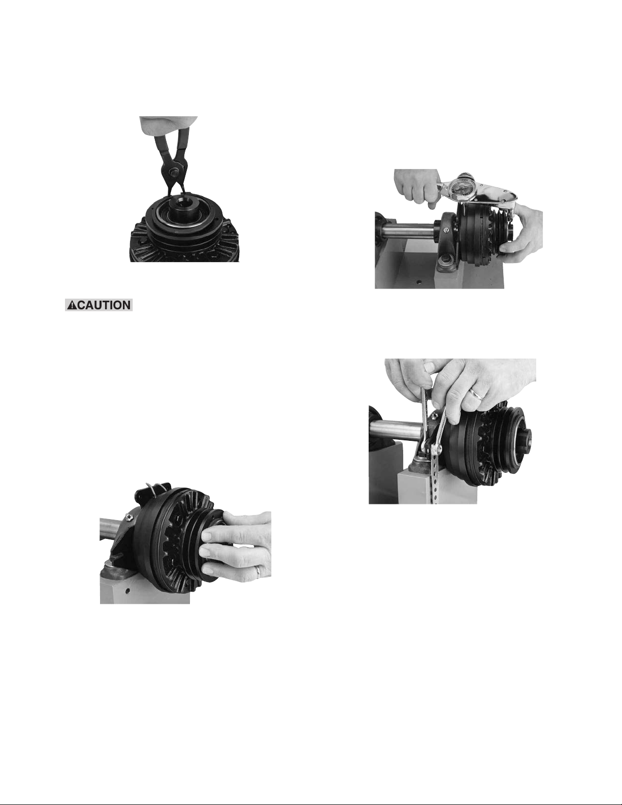
3. Install the furnished sheave or pulley retaining
ring with retaining ring pliers.
(See Figure 3)
Figure 3
6. Tighten the hub setscrews into the shaft (See
Figure 5) to the appropriate torque for your size
unit:
Size Torque
25 80 in.lbs.
55 160 in.lbs.
When installing this or other
retaining rings, be sure to hold the ring with
one hand so it will not spring away, endangering personnel and property, should the pliers
lose their grip on the ring. Safety glasses
should always be worn when installing or
removing retaining rings.
4. If used, install the Warner Electric conduit box in
accordance with its furnished instructions.
5. Place the ATT clutch onto its shaft, making sure
it is properly positioned over the shaft key. (See
Figure 4)
Figure 5
115 275 in.lbs.
Figure 6
Assure proper alignment of driving and driven
sheave, pulley or sprocket before tightening the
setscrews.
Figure 4
Note: The Warner Electric special furnished key
must be used with ATTC-25-7/8” bore units.
Warner Electric • 800-234-3369 819-0339
3
Page 4
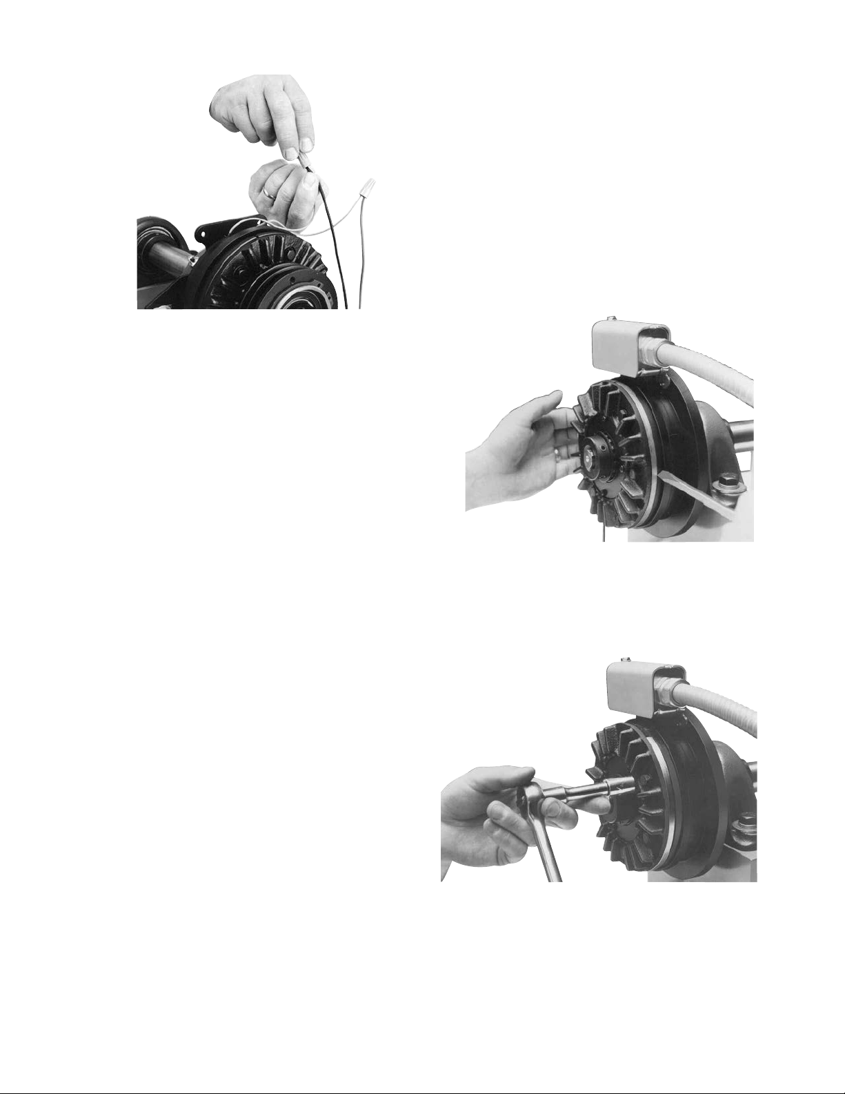
Figure 7
7. Install the field restraining arm. (See Figure 6)
Note: The field must retain a degree of movement freedom to compensate for bearing and
shaft alignment tolerances.
8. When using a Warner Electric tension control, follow the connection diagram supplied
with the control. (See Figure 7)
Complete Clutch Repair - On the Shaft
The new ATT design incorporates the latest in
advanced technology providing a rugged, durable,
patented design for long life, and maximum heat dissipation. Patented, easy to replace, friction surfaces
extend the design life for continued like-new performance. The ATT offers complete repair on the
shaft following ten easy steps. The repair can be
completed utilizing the parts in the friction face
replacement kit.
1. Move the clutch rotor towards the field for disassembly and reassembly. (See Figure 8)
Note: If a Warner Electric TCS-210, -220, -310,
or – 320 control is used, add a 68 ohm, 25 watt
resister or a dummy coil (part no. 275-3843)
across the current sense circuit. Although the
TCS series controls are recommended, a MCS
control can be used with normal hook-up.
9. Your ATT clutch is now ready for its static test.
Apply DC voltage to the clutch coil through the
clutch control. The armature should pull against
the friction material face.
10. Install the drive belt or chain.
11. Run the clutch under its operating load.
12. Your ATT clutch may not achieve its full torque
until after a short “break-in” period. To break in
the clutch, cycle it on and off under full load at
operating speed a minimum of ten times in quick
Figure 8
2. Remove hex head capscrews, washers and lockwashers to loosen the armature segments from
the cast iron carrier.
(See Figure 9)
Figure 9
Warner Electric • 800-234-3369 819-0339
4
Page 5
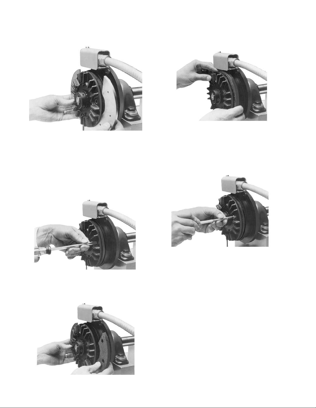
3. Lift out the two worn armature segments.
(See Figure 10)
Figure 10
Note: Although an AT brake is shown in these
instructions, identical procedures apply to a
clutch.
4. Remove the screws that attach the friction material segments to the clutch rotor through the
appropriate access holes. (See Figure 11)
6. Insert two new friction material segments. The
recessed holes should be facing away from the
magnet body. (See Figure 13)
Figure 13
7. Attach the new friction material segments to the
clutch rotor or brake magnet with screws through
the appropriate access holes. Apply one drop of
Loctite®(grade AA or equivalent) to each screw.
(See Figure 14)
Figure 14
Note: Use only the screws included with the
Figure 11
5. Lift out the worn friction material segments. (See
Figure 12)
repair kit since any other screws may damage
the unit. Tighten screws to 18 to 22 inch pounds
torque.
Figure 12
Warner Electric • 800-234-3369 819-0339
5
Page 6
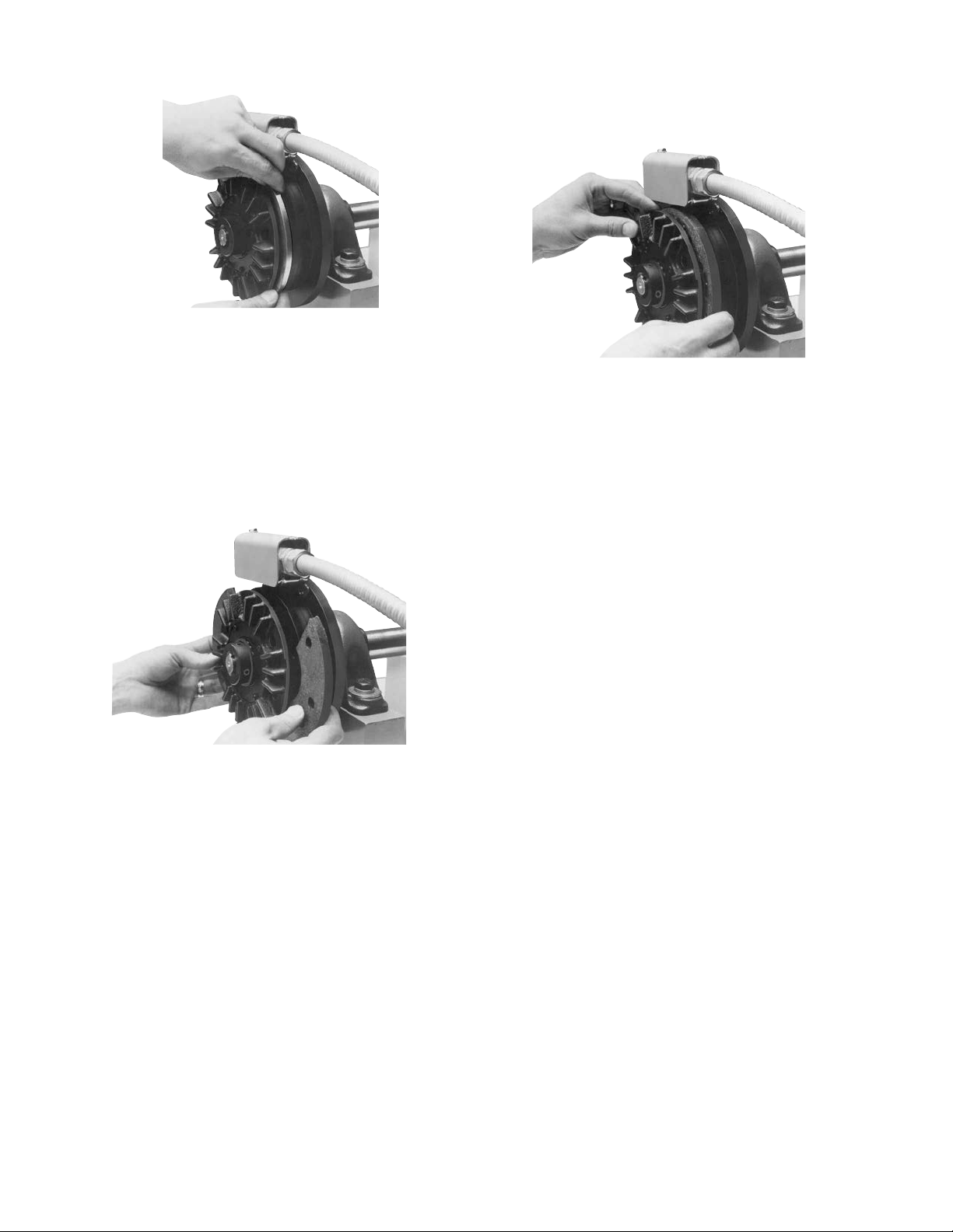
Figure 15
8. Insert the two new armature segments. (See
Figure 15)
10. Reset the gap by moving the clutch rotor away
from the field or brake armature toward the magnet. (See Figure 17)
Figure 17
9. Attach the new armature segments to the cast
iron carrier with hex head capscrews, lockwashers and washers. Apply one drop of Loctite
(grade AA or equivalent) to each screw. (See
Figure 16) Tighten to the appropriate torque for
your size unit.
Figure 16
Size Torque
ATT 25 29-35 in.-lbs.
ATT 55 60-84 in.-lbs.
ATT 115 60-84 in.-lbs.
11. Your ATT clutch is now ready for its static test.
Apply DC voltage to the clutch coil through the
clutch control. The armature should pull against
the friction material face.
12. Install the drive belt or chain.
13. Run the clutch under its operating load.
14. Your ATT clutch many not achieve its full torque
until after a short “break-in” period. To break in
the clutch, cycle it on and off under full load at
operating speed a minimum of ten times in quick
succession.
Your ATT clutch is now ready to run.
Warner Electric • 800-234-3369 819-0339
6
Page 7

Clutch Service – Major
A major rebuild of an ATT clutch can be accomplished by following these instructions to replace the
parts furnished in the appropriate Warner Electric
clutch rebuild kit. Part numbers and component
descriptions for these kits are found on page 19 of
this manual. Item numbers in these instructions refer
to clutch components shown on page 18, exploded
view. Proceed as follows:
1. Turn off all power to the clutch.
2. Disconnect the coil wires from the incoming control unit wires. (See Figure 18)
4. Loosen the setscrews (Item 8) which hold the
clutch to its shaft. (See Figure 20)
Figure 20
5. Remove the clutch from its shaft by pulling
and/or gently tapping the hub with a hammer
and drift. (See Figure 21)
Figure 18
3. Disconnect the field anti-rotation pin or field
restraining arm (Item 19). (See Figure 19)
Figure 19
Figure 21
Note: Do not hit the outer portion of the clutch
outboard of the hub as this may severely damage
it.
Warner Electric • 800-234-3369 819-0339
7
Page 8

6. Remove the retainer ring (Item 13). (See Figure
22)
Figure 24
Figure 22
When removing this or other
retaining rings, be sure to hold the retaining
ring with on hand so it will not spring away
and endanger personnel and property should
the pliers lose their grip on the ring. Safety
glasses should always be worn when
installing or removing rings.
7. Remove the field assembly (Item 12) and bearing
(Item 11) by locating and supporting on the rotor
outer diameter (Item 10) and pressing on the hub
(Item 7). (See Figure 23)
Note: Use caution to avoid damaging the epoxy
covering the coil.
9. Press the new bearing (Item 11) into the field
assembly by pressing on the bearing outer race.
Do not press on the bearing inner race or
damage to the bearing will result, making it
unusable. (See Figure 25)
Figure 25
10. Remove the rotor assembly (Item 10) from the
hub (Item 7). (See Figure 26)
Figure 23
8. Remove the bearing (Item 11) from the field
assembly (Item 12) by pressing on the inner race
while supporting the field assembly on its face.
(See Figure 24)
Figure 26
Warner Electric • 800-234-3369 819-0339
8
Page 9

11. Remove the screws which retain the friction disc
segments. (See Figure 27)
Apply a drop of Loctite grade AA or equivalent to
each screw prior to installation. Tighten each
screw to 18-22 in. lb. torque. (See Figure 30)
Figure 30
Figure 27
12. Lift the friction disc segments off the rotor. (Item
10) (See Figure 28)
Figure 28
13. Clean all foreign matter from rotor mounting surface. Install the new friction disc segments (Item
10-1) with new screws included with the kit. (See
Figure 29)
Note: Use only the screws included with the kit
as any others may damage the clutch.
14. Remove the snap ring (Item 1) from the armature
hub assembly. (See Figure 31)
Figure 31
When installing or removing
this or other retaining rings, be sure to hold
the ring with one hand so it will not spring
away, endangering personnel and property
should the pliers lose their grip on the ring.
Safety glasses should always be worn when
installing or removing retaining rings.
Figure 29
Warner Electric • 800-234-3369 819-0339
9
Page 10

Remove the pulley, sheave, or sprocket if it interferes with removing the capscrews (Item 9-2).
(See Figure 32)
Figure 35
Figure 32
15. Disassemble the armature hub assembly by
removing capscrews (Item 9-2), lock washers and
armature segment (Item 9-1). (See Figure 33)
Figure 33
Remove the setscrews (Item 8). (See Figure 34)
Locate and support on the sheave end of the
assembly near the fins and press on the field end
of the splined hub (Item 7). (See Figure 36)
Figure 36
To remove the hub and bearing assembly,
remove the bearings (Item 5) and spacer (Item 6)
from the hub (Item 7) by pressing them off. (See
Figure 37)
Figure 34
Remove the external and internal retaining rings
(Items 3 and 4) from the splined hub (Item 7) and
the armature hub (Item 2). (See Figure 35)
Warner Electric • 800-234-3369 819-0339
10
Proceed with reassembly per the following
instructions:
Figure 37
Page 11

Note: It is imperative that all bearings be
Support
Support
Press
Force
Bearing
Hub
Shoulder
Hub
Press
Force
Armature
Assembly
Support
Support
Adapter
Shoulder
Press Force
Press Force
Armature
Assembly
Support
Support
Adapter
Shoulder
Spacer
Spacer
installed exactly as instructed to avoid damage
to the bearings.
Apply one drop of Loctite grade AA or equivalent
to each capscrew prior to installation.
(See Figure 38)
Figure 38
Install the new armature segments (Item 9-1)
supplied in the kit onto the armature hub, (Item 2)
using capscrews and washers (Items 9-2, and 9-
3). (See Figure 39)
16. Install the inner adapter bearing (Item 5) onto the
hub, (Item 7) by pressing on the inner race of
the bearing. With the end of the hub supported
as shown in Figure 41, press the bearing until its
inner race locates against the hub shoulder.
Figure 41
17. Press the hub and bearing into the Adapter
Assembly until the outer race of the bearing
locates against the shoulder of the adapter hub.
Note that the force is to be exerted on the
outer race. Support the armature face as shown
in Figure 42.
Figure 42
Figure 39
Tighten the capscrews (See Figure 40) to the
appropriate torque for your size unit:
Size Torque
25 29-35 in.-lbs.
55-115 60-84 in.-lbs.
Figure 40
Warner Electric • 800-234-3369 819-0339
18. Install the spacer (Item 6) as shown in Figure 43.
Figure 43
11
Page 12

19. Press the outer bearing (Item 5) into place by
Spacer
Support
Support
Press Force
Evenly A pplied
Press Force
Eve nly Appl ied
Support
Support
Press
Force
Bearing
Hub
Shoulder
Hub
Press
Force
Support
Maximum
.05 0 Air gap
All Arou nd
Push
Push
Spline
Detent
Ring
Support
Press
Force
Shell
Assembly
Press
Force
Support Support
applying force evenly against the bearing
outer and inner races simultaneously while
supporting the armature face. Continue pressing
until the outer race firmly locates against the
spacer. (See Figure 44)
Figure 44
20. Install the external and internal retaining rings
(Items 3 and 4) adjacent to the outer bearing.
(See Figure 45)
21. Install the rotor assembly onto the hub (Item 7)
making sure that the spline teeth are aligned.
(See Figure 46)
Figure 46
22. Press the field assembly onto the hub by pushing the inner race of the bearing while support-
ing on the hub. Apply force until the inner race of
the bearing is located flush against the shoulder
adjacent to the spline. (See Figure 47)
Figure 47
Figure 45
Install the retaining ring (Item 13) on the hub with
Note: The Armature Assembly must rotate freely
on the hub. Inspect to insure that the inner bearing is still firmly located against the adapter
snap ring pliers. (See Figure 48)
Rotate the hub. No interference between the
shell and rotor is allowable.
shoulder as previously shown in Figure 42. When
inspecting, place unit firmly on flat surface with
exposed hub end up.
this or other retaining rings, be sure to
When installing or removing
hold the ring with one hand so it will not
spring away, endangering personnel and
property, should the pliers lose their grip
on the ring. Safety glasses should always
be worn when installing or removing
Warner Electric • 800-234-3369 819-0339
12
Figure 41
retaining rings.
Page 13

Figure 48
23. Reinstall the sheave, pulley, or sprocket, and key.
(See Figure 49)
24. Reinstall the clutch assembly on the shaft, placing the key in its keyway. (See Figure 51)
Figure 51
25. Tighten the hub setscrews onto the key (See
Figure 52) to the appropriate torque for your size
unit:
Size Torque
25 80 in.-lbs.
55 160 in.-lbs.
115 275 in.-lbs.
Figure 49
Reinstall the sheave retainer ring (Item 1) (See
Figure 50) and conduit box, if used. Refer to the
conduit box installation instructions.
Figure 50
Assure proper alignment of driving and driven
sheave, pulley, or sprocket before tightening set
screws.
Figure 52
26. Secure the field by its pin or restraining arm
accessory to avoid rotation. (See Figure 53)
Figure 53
Warner Electric • 800-234-3369 819-0339
13
Page 14

27. Reconnect the wires. (See Figure 54)
Figure 54
28. Your ATT clutch is now ready for its static test.
Apply DC voltage to the clutch coil through the
clutch control. The armature should pull against
the friction material face.
29. Install the drive belt or chain.
30. Run the clutch under its operating load.
31. Your ATT clutch may not achieve its full torque
until after a short “break-in” period. To break-in
the clutch, cycle it on and off under full load at
operating speed a minimum of ten times in quick
succession.
Your ATT clutch is now ready to run.
Warner Electric • 800-234-3369 819-0339
14
Page 15

ATT Clutch Troubleshooting Guide
If performance problems are present after carefully following the instructions in this manual, use the
following checklist.
Symptom Check
Problem Possible Cause
Clutch Rotor will not move or engage when • Coil Resistance
power is applied to the coil Coil may be open. See Chart 1.
• Power Supply
Assure proper DC voltage is being delivered to the clutch.
• Airgap
If greater than .050” around entire periphery, reset gap.
Vibration • Runout
Assure that shaft on which the clutch is mounted doesn’t have
excessive runout.
• Shaft Engagement
Assure adequate shaft length and diameter engagement in the hub.
Excessive Start or Stop Times • Power Supply
Assure proper DC voltage is being delivered to the clutch.
• Adequate Burnishing
Unit must be run and cycled a few times to achieve full rated torque.
• Friction Surfaces
Replacement may be required.
• Friction Surfaces
Installation of replacement friction material or armature segments
may be incorrect and not allow full contact.
Clutch/Brake Size Coil Voltage Approx. Coil Resistance (Ohms)
25 24 20.6
90 290
55 24 19.6
90 230
115 24 16.5
90 182
Chart 1
Warner Electric • 800-234-3369 819-0339
15
Page 16

Dimensions
Clearance
for 1/4" bolts
O
T
Optional
Restraining Strap
G
N
H
.750
Typ
S
R
Optional
Conduit
Box
F
0.875
Wire Protector
included with
Clutch
Key and Retaining Ring
included with Clutch
1.544
See
Detail
View
A
C
M
L
K
P
B
D
J
E
Q
W
U
V
90°
1/4-20 UNC thru.
(2) Jackscrew Holes
on X dia.
Detail View
Bore-to-size Requirements
Bore-to-size data
drawing for pulley,
sheaves, and
sprockets. See Boreto-size data on page
16.
Specifications
Model Size Voltage DC Unit Inertia*-WR2(lb.ft.2) Max. RPM Weight (lbs.) Static Torque (lb.ft.) @ 1800 RPM
25 6 Clutch .048 3600 8 25 12 lb. ft.
55 6 Clutch .173 3600 18 55 20 lb. ft.
115 6 Clutch .483 3600 28 115 30 lb. ft.
Warner Electric • 800-234-3369 819-0339
16
24 .048 3600 8 25 12 lb. ft.
90 .048 3600 8 25 12 lb. ft.
24 .173 3600 18 55 20 lb. ft.
90 .173 3600 18 55 20 lb. ft.
24 .483 3600 28 115 30 lb. ft.
90 .483 3600 28 115 30 lb. ft.
Dynamic Torque
Page 17

( ) denotes millimeters
ABCDEFGHJK L MT
Model Dia. Max. Nom. Dia. Max. Max. Max. Max. Dia. Max. Nom. Max. Nom.
25 3.60 4.39 2.375 1.080 4.748 3.767 3.282 5.11 4.822 1.68 1.003/.991 .715/.703 .375
55 3.95 4.935 2.925 1.40 5.182 3.767 4.032 5.11 6.275 1.817 1.113/1.101 – .375
115 5.254 5.977 3.102 1.86 6.089 3.767 4.246 10.11 7.906 2.467 1.539/1.523 – .375
Max. Nom. Max.
(91.44) (111.51) (60.33) (27.43) (120.60) (95.68) (83.36) (129.79) (122.49) (42.67) (25.48/25.17) (18.16/17.86) (9.53)
(100.33) (125.35) (74.30) (35.56) (131.62) (95.682) (102.412) (129.792) (159.39) (46.152) (28.27/27.97) (9.53)
(133.452) (151.822) (78.792) (47.242) (154.662) (95.682) (107.852) (256.792) (200.812) (62.662) (39.09/38.68) (9.53)
Model Holes Thread Size Depth Circle Nom. Nom. Nom. Min. Min.
25 3 1/4-20 .500 3.00 .500 .036 3.586 .752 .279
55 4 1/4-20 .635 3.50 .500 .081 4.156 .722 .265
115 4 5/16-18 .830 4.75 .500 .237 4.927 .504 .265
No. of N Max. Bolt OP Q RS
(12.7) (0.91) (91.10) (19.08 (7.09)
(12.7) (2.06) (105.56) (18.34) (6.73)
(12.7) (6.02) (125.15) (12.80) (6.73)
Bore to Size Data
Model Bore Dia. Keyway Height Keyway Width Bolt Circle
25 2.502/2.500 2.601/2.591 .1905/.1855 3.00
55 3.002/3.000 3.099/3.089 .1905/.1885 3.50
115 4.002/4.000 4.127/4.117 .378/.376 4.50
UV WX
(63.55/63.50) (66.06/65.81) (4.84/4.79) (76.20)
(76.25/76.20) (78.71/78.46) (4.84/4.79) (88.90)
(101.65/101.60) (104.83/104.57) (9.60.9.55) (114.30)
Bore Size and Keyways
Size Unit Bore Key
ATC-25 .5025 12.76 1/8 Sq.
.5005 12.71
.6275 15.94 3/16 Sq.
.6255 15.89
ATC-25 .7525 19.11 3/16 Sq.
ATC-55 .7505 19.06
ATC-25 .8775 22.29 3/16 Sq.
ATC-55 .8755 22.24
ATC-55 1.0025 25.46 1/4 Sq.
1.0005 25.41
ATC-55 1.1275 28.64 1/4 Sq.
ATC-115 1.1255 28.59
ATC-115 1.2525 31.81 1/4 Sq.
1.2505 31.76
1.3775 34.99 5/16 Sq.
1.3755 34.94
1.5025 38.16 3/8 Sq.
1.5005 38.11
Warner Electric • 800-234-3369 819-0339
17
Page 18

Parts List
3
4
1
11
14
16
18
17
15
13
19
9-1
7
12
8
10-1
10
20
Optional
Optional
Optional
Optional
6
5
9-3
9-2
9-2
9-3
9-4
2
Warner Electric • 800-234-3369 819-0339
18
Page 19

Component Parts
ATC-25 ATC-55 ATC-115
Item Description Part No. Qty. Part No. Qty. Part No. Qty.
1 Retaining Ring 748-0734 1 748-0725 1 748-0738 1
2 Armature Hub 540-0907 1 540-0852 1 540-0863 1
3 Retaining Ring 748-0732 1 748-0726 1 748-0737 1
4 Retaining Ring 748-0731 1 748-0728 1 748-0736 1
5 Bearing 166-0278 2 166-0277 2 166-0279 2
6 Spacer 807-0119 1 807-1061 1 807-1063 1
7 Splined Hub 111
1/2” Bore 540-0910
5/8” Bore 540-0911
3/4” Bore 540-0912 540-1501
7/8” Bore 540-0913 540-1502
1” Bore 540-1503
1-1/8” Bore 540-1504 540-0857
1-1/4” Bore 540-0858
1-3/8” Bore 540-0859
1-1/2” Bore 540-0860
8 Setscrew 797-1393 2 797-1386 2 797-1395 2
*9-1 Armature 110-0220 1 110-0218 1 110-0223 1
*9-2 Screw 797-1519 4 797-1462 6 797-1463 6
*9-3 Lockwasher 950-0355 6 950-0355 6
*9-4 Flatwasher 950-0023 2 950-0023 2
*10 Rotor 5161-751-001 1 5162-751-001 1 5163-751-001 1
10-1 Facing Assembly 5161-445-003 1 5162-445-003 1 5163-445-003 1
*11 Bearing 166-0283 1 166-0284 1 166-0279 1
12 Field Assembly 111
6 volts DC 5161-451-002 5162-451-002 5163-451-002
90 volts DC 5161-451-003 5162-451-003 5163-451-003
24 volts DC 5161-451-004 5162-451-004 5163-451-004
*13 Retainer Ring 748-0018 1 748-0727 1 748-0737 1
14 Adapter 104-0300 2
15 Screw 797-1396 4
16 Lockwasher 950-0102 4
Optional Accessory Items
17 Conduit box 5162-101-002 1 5162-101-002 1 5162-101-002 1
18 CBC-100 Control 6003-101-001 1 6003-101-001 1 6003-101-001 1
19 Restraining Arm Assembly 5162-101-004 1 5162-101-004 1 5163-101-004 1
20 Timing Belt and V Belt Pulleys; See “Standard Sheaves and Pulleys” Chart, P-1234 page 69.
Kit Items
Clutch Rebuild Kit 5161-101-011 1 5162-101-011 1 5163-101-011 1
(includes items 9-1, 9-2, 9-3, 9-4, 10, 11, 13)
Note: In some versions of this product, item 10 consists of a rotor and a replaceable face.
Friction Face Replacement Kit 5161-101-007 5162-101-007 5163-101-007
For Clutches with Replaceable Friction Face Only
Refer to Service Manual P-217-1
Warner Electric • 800-234-3369 819-0339
19
Page 20

Warranty
Warner Electric LLC warrants that it will repair or replace (whichever it deems advisable) any
product manufactured and sold by it which proves to be defective in material or workmanship
within a period of one (1) year from the date of original purchase for consumer, commercial or
industrial use.
This warranty extends only to the original purchaser and is not transferable or assignable without
Warner Electric LLC’s prior consent.
Warranty service can be obtained in the U.S.A. by returning any defective product, transportation
charges prepaid, to the appropriate Warner Electric LLC factory. Additional warranty information
may be obtained by writing the Customer Satisfaction Department, Warner Electric LLC, 449
Gardner Street, South Beloit, Illinois 61080, or by calling 815-389-3771.
A purchase receipt or other proof of original purchase will be required before warranty service is
rendered. If found defective under the terms of this warranty, repair or replacement will be made,
without charge, together with a refund for transportation costs. If found not to be defective, you
will be notified and, with your consent, the item will be repaired or replaced and returned to you
at your expense.
This warranty covers normal use and does not cover damage or defect which results from
alteration, accident, neglect, or improper installation, operation, or maintenance.
Some states do not allow limitation on how long an implied warranty lasts, so the above limitation
may not apply to you.
Warner Electric LLC’s obligation under this warranty is limited to the repair or replacement of the
defective product and in no event shall Warner Electric LLC be liable for consequential, indirect,
or incidental damages of any kind incurred by reason of the manufacture, sale or use of any
defective product. Warner Electric LLC neither assumes nor authorizes any other person to give
any other warranty or to assume any other obligation or liability on its behalf.
WITH RESPECT TO CONSUMER USE OF THE PRODUCT, ANY IMPLIED WARRANTIES WHICH
THE CONSUMER MAY HAVE ARE LIMITED IN DURATION TO ONE YEAR FROM THE DATE OF
ORIGINAL CONSUMER PURCHASE. WITH RESPECT TO COMMERCIAL AND INDUSTRIAL
USES OF THE PRODUCT, THE FOREGOING WARRANTY IS IN LIEU OF AND EXCLUDES ALL
OTHER WARRANTIES, WHETHER EXPRESSED OR IMPLIED BY OPERATION OF LAW OR
OTHERWISE, INCLUDING, BUT NOT LIMITED TO, ANY IMPLIED WARRANTIES OF
MERCHANTABILITY OR FITNESS.
Some states do not allow the exclusion or limitation of incidental or consequential damages, so
the above limitation or exclusion may not apply to you. This warranty gives you specific legal
rights and you may also have other rights which vary from state to state.
Changes in Dimensions and Specifications
All dimensions and specifications shown in Warner Electric catalogs are subject to change without
notice. Weights do not include weight of boxing for shipment. Certified prints will be furnished
without charge on request to Warner Electric.
Warner Electric LLC
31 Industrial Park Road • New Hartford, CT 06057
815-389-3771 • Fax: 815-389-2582
www.warnerelectric.com
P-220 819-0339 6/12 Printed in USA
 Loading...