

Page 1
AC10 Measuring System
P-2012-2
819-0402
Installation Instructions
Page 2

Contents
Introduction . . . . . . . . . . . . . . . . . . . . . . . . . . . . 2
System Overview. . . . . . . . . . . . . . . . . . . . . . . 3
AC10 Tensioncells . . . . . . . . . . . . . . . . . . . . . . 4
AC10 Electronics . . . . . . . . . . . . . . . . . . . . . . . 5
AC10 Specifications . . . . . . . . . . . . . . . . . . . . 6
Pushbutton Key Functions . . . . . . . . . . . . . . . 7
Installation
Pre-Installation Inspection. . . . . . . . . . . . . . . . 8
Mechanical Installation . . . . . . . . . . . . . . . . . . 8
Electrical Installation . . . . . . . . . . . . . . . . . . . 10
Electrical Connections. . . . . . . . . . . . . . . . . . 10
Initial Electrical Checks . . . . . . . . . . . . . . . . . 12
AC10 Setup Procedure . . . . . . . . . . . . . . . . . 13
Programmable Threshold Relay . . . . . . . . . . 15
Reset Tare to Zero . . . . . . . . . . . . . . . . . . . . . 15
Troubleshooting . . . . . . . . . . . . . . . . . . . . . . . 16
Failure to follow these instructions may result in product damage, equipment damage, and serious or fatal injury to
personnel.
Introduction
This manual is intended for use by qualified personnel to assist them in the safe setup and
operation of the Warner Electric AC10 Tension
Measuring System. Warner Electric has made
every effort to insure the accuracy and completeness of the information and recommends
that all procedures be read and understood
before performing them. Please contact Warner
Electric with any questions regarding any information contained in this manual.
Dimension Drawings
AC10 Tensioncells . . . . . . . . . . . . . . . . . . . . . 18
Model Number Designation. . . . . . . . . . . . . . 18
PSAC10 . . . . . . . . . . . . . . . . . . . . . . . . . . . . . 19
Warranty . . . . . . . . . . . . . . . . . . . . . Back Page
Warner Electric • 800-825-9050 P-2012-2
2
Page 3
System Overview
J
3
J4
J6
J5
W
arner
Part# 80-165 Rev
Serial#
Setup
Rapid
E
xit
Setup
E
nter
J7
J8
J9
J
1
J2
PSAC10 Board
Power
Switch
Output #1
Output #2
Control
Analog or Digital
Meter
Drive
Cell #1/Total/Cell #2
Switch
AC-10 Tensioncells
Threshold
Alarm
RS-422
Interface
MCS2000-CTDA
MCS2000-CTDA
Control
Analog or Digital
Meter
Drive
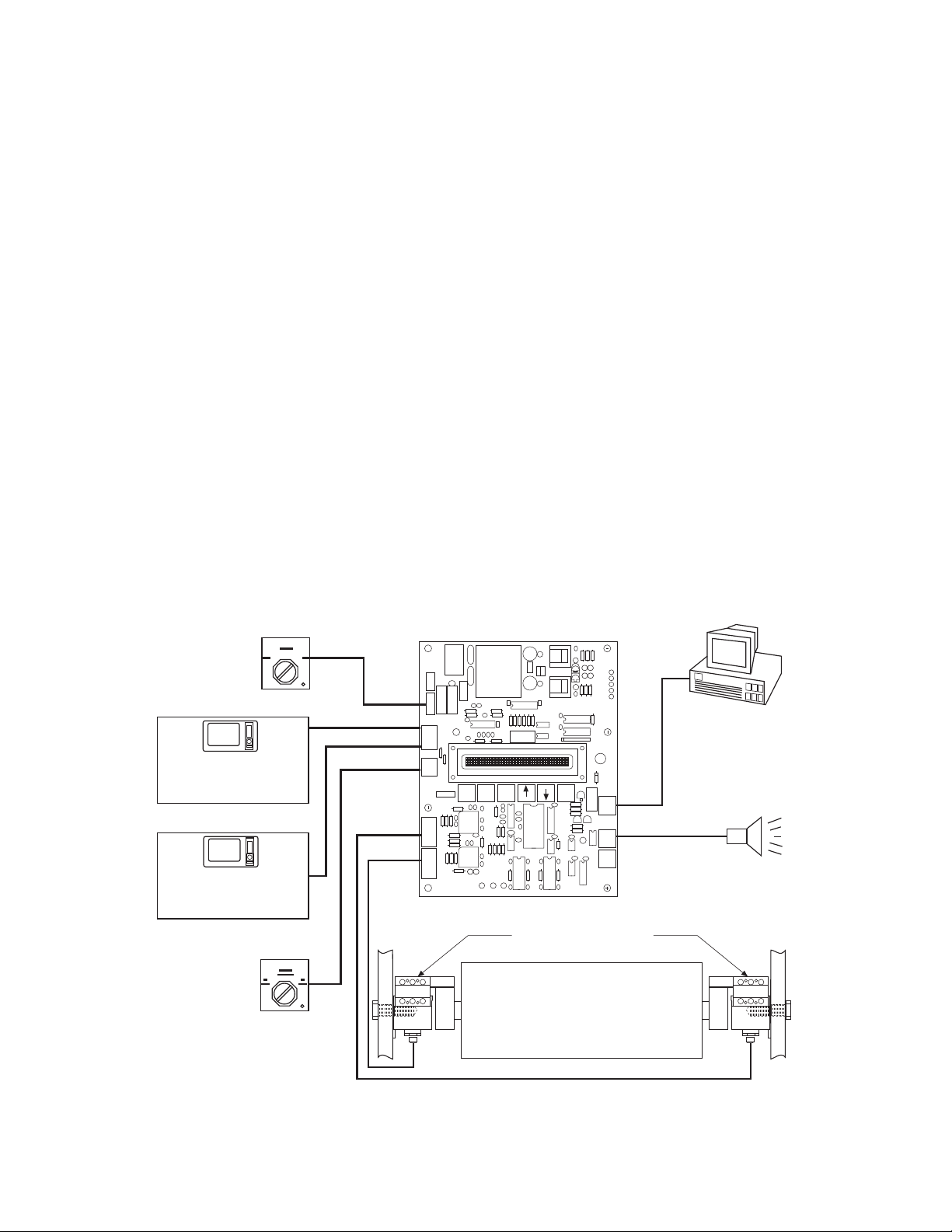
The AC10 Tension Measuring System is designed
to measure tension on continuous strip processing lines and equipment. The system consists of
two AC10 Tensioncells, the PSAC10 power supply
amplifier board, and two cables for connecting the
Tensioncells to the board.
AC10 Tensioncells are mounted in pairs, one at
each end of the measuring roll. During operation
the Tensioncells continuously measure the
mechanical tension force applied to the measuring
roll. When the force is applied, the load plate
deflects toward or away from the base block
depending on the resultant force acting upon the
Tensioncell. Deflection toward the base block is
defined as the "Compression Mode.” Deflection
away from the base block is defined as the
"Tension Mode." AC10 Tensioncells work equally
well in either mode.
The mechanical deflection of the load plate is
converted into an electrical output signal by the
AC Linear Variable Differential Transformer
(LVDT). Displacement of the LVDT core caused
by variations in web tension results in an output
signal to the PSAC10 board directly proportional
to the applied tension.
The analog outputs from the Tensioncells are converted into digital signals by the microprocessorbased electronics. The signals are conditioned,
processed, and summed to produce two individually scaleable, -10 to +10 volt DC analog outputs
to a tension indicator, drive or a MCS2000 CTDA
control which can be used to monitor or control
tension. The percent tension applied to each
Tensioncell and the total tension are displayed on
the board mounted 16-character liquid crystal
display (LCD).
Terminals are also provided for connecting a user
supplied On/Off power switch, 1-only 2-only
switch, and RS-422 PC interface. A threshold
alarm relay connection is also provided.
Note: When using the PSAC10 board, connect the outputs to the MCS2000 CTDA. There is no
need to use the MCS2000 CTLC, because the signal is amplified and summed in the PSAC10.
Warner Electric • 800-825-9050 P-2012-2
3
Page 4
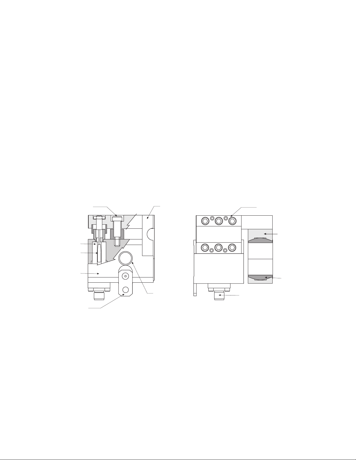
AC10 Tensioncells
Shaft Support
Block
Self-Aligning
Shaft Support
Bushing
Electrical
Connector
5/8-1 1 UNC
Mounting
Hole
Load Plate
C-Flexure
Mechanical Stop
LVDT
LVDT Core
Base Block
Locating Tab
AC10 Tensioncells are available in three capacity ranges for non-rotating shaft applications
with maximum resultant force plus tare load of
60, 170, or 500 pounds respectively.
The rugged, all-steel construction of the AC10
Tensioncell includes four basic components: the
one-piece base block, the patented C-Flexure,
the load plate, and the shaft support block. The
factory-set mechanical stop provides overload
protection up to ten times the maximum rated
load capacity of the unit.
Each unit is wall mounted by means of a single
bolt located in line with the integral self-aligning,
stainless steel shaft support bushing and the
centerline of the roll shaft. This permits the
Tensioncell to be rotated and mounted at the
required angle around the axis of the measuring
roll. The locating tab at the bottom of the unit
locks it in position.
The primary conversion element between the
mechanical tension force and the electrical output signal is an AC Linear Variable Differential
Transformer (LVDT). The LVDT electrical elements are encapsulated and sealed against
shock, vibration, or tampering. Input and output
circuits are isolated from each other and from
the Tensioncell body. This permits the
Tensioncells to be used in floating ground electrical systems.
Warner Electric • 800-825-9050 P-2012-2
4
Page 5
AC10 Electronics
J3
J4
J6
J5
Warner
Part# PSAC10
Serial#
Setup
Rapid
Exit
Setup
Enter
J7
J8
J9
J1
J2
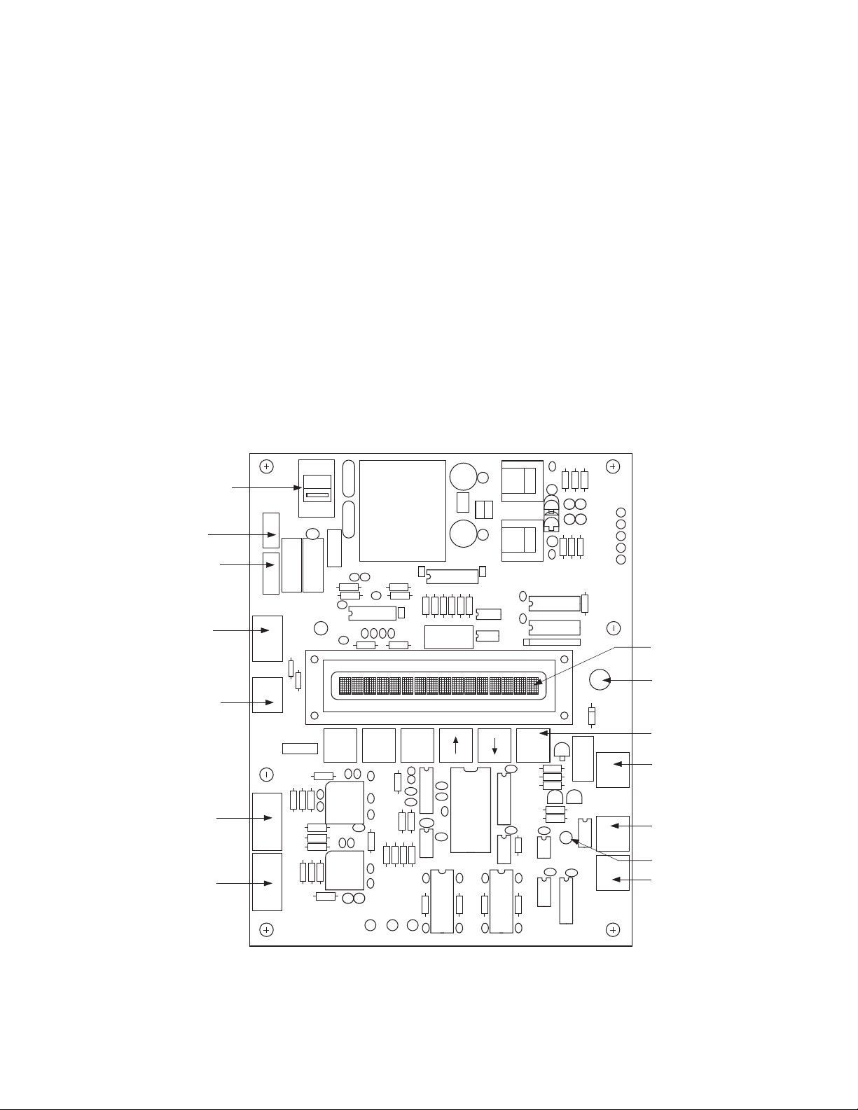
Input Power
Selector Switch
Input Power
Terminal
Power On
Switch Terminal
Output #1
Output #2
Terminal
Cell #1/T otal/Cell#2
Switch Terminal
Tensioncell #1
Terminal
Tensioncell #2
Terminal
16-Character LCD
LCD Brightness
Adjustment
Pushbutton Keys
Threshold Relay
Terminal
RS-422 Output
Terminal
Run Mode LED
Spare
230V
The AC10 microprocessor-based electronics
adds ease of setup, versatility, and accuracy of
the overall system by eliminating the need for
potentiometers to adjust or setup the system.
All adjustments and system settings are performed by using the pushbutton keys on the
board. During setup, alphanumeric prompts are
displayed on the 16-character LCD to guide the
user through the setup procedure.
Other features of the PSAC10 board include:
Two individually scaleable -10 to +10 volt DC
outputs
Run Mode LED
Programmable threshold relay
Cell#1/Total/Cell#2 switch connection
LCD Brightness Adjustment
Switch selectable 115/230 volt AC input
power
An RS422 Serial Output terminal is also provided for interfacing the AC10 system with a PC to
monitor and/or record the percent tension
applied to each Tensioncell. Data is transferred
in ASCII text format. The RS422 output can be
converted to RS-232.
Warner Electric • 800-825-9050 P-2012-2
5
Page 6

Specifications
AC10 Tensioncells
Dimensions (I x w x h) . . . . . . . . . . . . . . . . . . . . . . . . . . . . . . . . . . . . . . . . . . . . . . . .3.00" x 3.44" x 3.90"
Maximum Load Capacity (tension plus tare)
AC10A . . . . . . . . . . . . . . . . . . . . . . . . . . . . . . . . . . . . . . . . . . . . . . . . . . . . . . . . . . . . . . . . . . .60 pounds
AC10B . . . . . . . . . . . . . . . . . . . . . . . . . . . . . . . . . . . . . . . . . . . . . . . . . . . . . . . . . . . . . . . . . .170 pounds
AC10C . . . . . . . . . . . . . . . . . . . . . . . . . . . . . . . . . . . . . . . . . . . . . . . . . . . . . . . . . . . . . . . . . .500 pounds
Minimum Tension Load Required for Setup
AC10A . . . . . . . . . . . . . . . . . . . . . . . . . . . . . . . . . . . . . . . . . . . . . . . . . . . . . . . . . . . . . . . . . . . . .4 pounds
AC10B . . . . . . . . . . . . . . . . . . . . . . . . . . . . . . . . . . . . . . . . . . . . . . . . . . . . . . . . . . . . . . . . . . .10 pounds
AC10C . . . . . . . . . . . . . . . . . . . . . . . . . . . . . . . . . . . . . . . . . . . . . . . . . . . . . . . . . . . . . . . . . . .30 pounds
Standard Shaft Diameters (1/16" increments) . . . . . . . . . . . . . . . . . . . . . . . . . . . . . . . . . . . .1/2" to 1-1/2"
Overload Protection . . . . . . . . . . . . . . . . . . . . . . . . . . . . . . . . . . . . .10 times maximum rated load of unit
Maximum Deflection at Full Load . . . . . . . . . . . . . . . . . . . . . . . . . . . . . . . . . . . . . . . . . . . . . . . . . .0.010"
LVDT
Operating Temperature . . . . . . . . . . . . . . . . . . . . . . . . . . . . . . . . . . . . . . . . . . . . . . . . .250°F maximum
Excitation Voltage . . . . . . . . . . . . . . . . . . . . . . . . . . . . . . . . . . . . . . . . . . . . . . . . . . . . . .15 Vrms @5KHz
Output . . . . . . . . . . . . . . . . . . . . . . . . . . . . . . . . . . . . . .3.2 volts AC/inch displacement / volt excitation
Excitation Resistance . . . . . . . . . . . . . . . . . . . . . . . . . . . . . . . . . . . . . . . . . . . . . . . . . . .335 Ohms ±5%
Output Signal Resistance . . . . . . . . . . . . . . . . . . . . . . . . . . . . . . . . . . . . . . . . . . . . . . . .100 Ohms ±5%
Linearity . . . . . . . . . . . . . . . . . . . . . . . . . . . . . . . . . . . . . . . . . . . . . . . . . . . . . . . . . . . . . .0.1% of full scale
Hysteresis . . . . . . . . . . . . . . . . . . . . . . . . . . . . . . . . . . . . . . . . . . . . . . . . . . . . . . . . . . . .0.1% of full scale
Repeatability . . . . . . . . . . . . . . . . . . . . . . . . . . . . . . . . . . . . . . . . . . . . . . . . . . . . . . . . . .0.1% of full scale
Temperature Drift . . . . . . . . . . . . . . . . . . . . . . . . . . . . . . . . . . . . . . . . . . . . . . . . . . . . . . . . . .0.02% per °C
PSAC10 Power Supply/Amplifier Board
Dimension (I x w) . . . . . . . . . . . . . . . . . . . . . . . . . . . . . . . . . . . . . . . . . . . . . . . . . . . . . . . . . .8.75" x 6.88"
Maximum height of components above board . . . . . . . . . . . . . . . . . . . . . . . . . . . . . . . . . . . . . . . . . . .1.5"
Operating Temperature Range . . . . . . . . . . . . . . . . . . . . . . . . . . . . . . . . .32°F to +160°F (0°C to +70°C)
Input Voltage (switch selectable) . . . . . . . . . . . . . . . . . . . . . . . . . .115/230 VAC, 50-60 Hz, <1.0 Ampere
Output Voltage (two individually scaleable)
Maximum cable distance between Tensioncell and board . . . . . . . . . . . . . . . . . . . . . . . . . . . . . .100 feet
(The output load to the board must be 2 kΩ or greater)
Threshold Relay Contact . . . . . . . . . . . . . . . . . . .1A @ 24 VDC, 500mA@ 120 VAC, 250 mA @ 220 VAC
RS-422 Data Rate . . . . . . . . . . . . . . . . . . . . . . . . . . . . . . . . . . . . . . . . . . . . . . . .300bps, NP, 8, 1 stop bit
. . . . . . . . . . . . . . . . . . . . . . . . . . . . . . . . . . . .-10 to +10 VDC
Warner Electric • 800-825-9050 P-2012-2
6
Page 7

Pushbutton Key Functions
The six pushbutton keys on the PSAC10 board are used to enter and exit the Setup Mode and to
make adjustments during the procedure. This section describes the various key functions and combinations that are used while setting up the system.
The UP arrow key is used to toggle between selections. It is also used to incremental-
RAPID
ly increase the output voltage each time the key is pressed. When the UP arrow and
RAPID keys are pressed simultaneously, the voltage value will change continuously
until the keys are released or the upper limit is reached. (See note below.)
ENTER
SETUP
EXIT
SETUP
RAPID
ENTERSETUP
RAPID
The DOWN arrow key is used to toggle between selections and to incrementally
decrease the output voltage each time the key is pressed. When the DOWN arrow and
RAPID keys are pressed simultaneously, the voltage value will change continuously
until the keys are released or the lower limit is reached. (See note below.)
The ENTER key is used to make selections and store values before proceeding to the
next Setup step.
Pressing and releasing these keys simultaneously accesses the Setup Mode. An asterisk (*) will display next to the right tension value.
Press and release these keys simultaneously to start the Setup procedure when in the
Setup Mode.
Press and release this key to exit the Setup Mode at any time. The system will return
the settings entered during the last completed setup procedure.
Press and release these keys simultaneously to enter the settings for the
Programmable Alarm Output.
SETUP
EXIT
Press and release these keys simultaneously to zero the system.
Note: During setup, the output voltage value will change approximately 5 millivolts each time the
Up or Down arrow key is pressed and released. Pressing and releasing the RAPID key and the
Up or Down arrow key simultaneously will change the value approximately 200 millivolts.
Holding the Rapid key and an arrow key in, will continuously change the value until the keys are
released.
Warner Electric • 800-825-9050 P-2012-2
7
Page 8
Installation
T
E
B
TW
T
RF
L
O
Tensioncell Model Number Designation
AC10B 18 W1
Code
A
B
C
Max. Load
Capacity
(pounds)
60
170
500
Min. Tension
Load for Setup
(pounds)
4
10
30
Example: AC10B18W1
AC10 = Side Mount Tensioncell
B = 170 pound capacity
18 = 1-1/8 inch shaft diameter
W1 = AC10 with split brushing
Support Bushing (AC10 only)
W1 = Split bushing for clamping
W2 = Solid bushing for expansion
08 1/2
09 9/16
10 5/8
11 11/16
12 3/4
13 13/16
14 7/8
15 15/16
16 1
17 1-1/16
18 1-1/8
19 1-3/16
20 1-1/4
21 1-5/16
22 1-3/8
23 1-7/16
24 1-1/2
Shaft Diameter
Pre-Installation Inspection
Before installing the AC10 system:
1. Insure all components are present. A typical
system consists of two AC10 Tensioncells,
one PSAC10 board, and two 30 foot lengths
of cable for connecting the Tensioncells to
the board. Refer to Model Number
Designation (Chart 1) below to verify load
capacity and shaft diameter.
2. Inspect all electrical and mechanical components for physical damage.
3. Promptly report any damage to the carrier
and Warner Electric.
Mechanical Installation – Tensioncells
The maximum rated load capacity must be
g
reater than or equal to (RF + TW) where W =
Tare Weight. The Web Resultant Force (RF) and
Tare Weight are always summed. Refer to the
Model Number Designation (Chart 1) below to
verify the shaft diameter, and that the maximum
rated load capacity of each unit.
Warner Electric also recommends the Resultant
Force (RF) be greater than 1/3 the maximum
load capacity of the Tensioncells.
Warner Electric side mount AC10 Tensioncells
are shipped in pairs designated W1 and W2.
The W1 unit has a split stainless steel, selfaligning bushing for clamping the measuring
roll. The bushing in the W2 unit is not split to
allow for shaft expansion.
AC10 Tensioncells are available in three capacity ranges. The rated load capacity should
always be larger than the maximum calculated
Tare Weight (W) plus the Resultant Force (RF).
To calculate the Resultant Force:
B
1. E = (180°-
/2) where B = Wrap Angle
2. RF = T x CosineE where T = Web Tension
Warner Electric • 800-825-9050 P-2012-2
8
Chart 1
Page 9

B
T
E
B
TW
T
RF
L
O
5/8-11 UNC
Mounting
Bolt
Machine
Frame
W1
Locating Tab
Centerline
Shaft Support
Block & Screws
W2
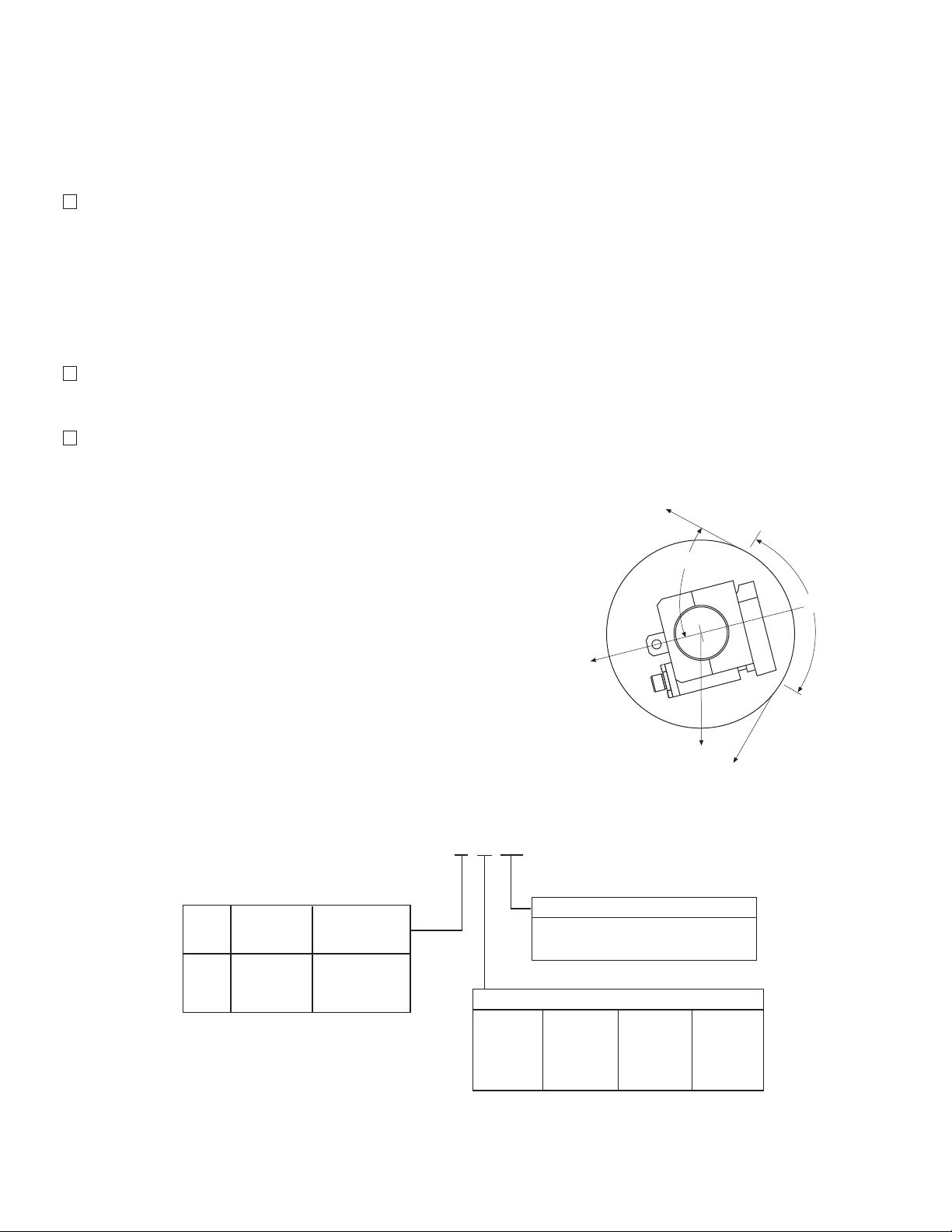
efore installing the Tensioncells, refer to
machine drawings, or other documentation
to determine the mounting angle. If the
mounting angle is not specified, mount the
Tensioncells so that the Tensioncell load line
(OL) bisects the wrap angle and aligns with
the Resultant Force (RF).
The Tensioncells are mounted to the machine
frame with a 5/8-11 UNC bolt. The bolt is in line
with the centerline of the shaft support bushing.
This allows the Tensioncells to be rotated
around the centerline of the roll so that the
Tensioncell load line (OX) aligns with the
Resultant Force (RF).
To install the Tensioncells:
1. Drill a 5/8" diameter hole through each side
of the machine frame at the measuring roll
location. The holes must be in line with each
other and roll centerline to insure that the roll
is level.
2. Fasten the Tensioncell to the machine frame
with the 5/8-11 UNC mounting bolt.
3. Rotate the Tensioncell to the proper mount-
ing angle and tighten the mounting bolt.
4. Drill a #6 (.204) hole concentric with the 1/4"
h
ole in the locating tab.
5. Remove the Tensioncell to provide clearance
to tap the hole for a 1/4-20 thread.
6. Repeat steps 2 through 5 for the Tensioncell
for the other end of measuring roll shaft.
7. Loosen, but do not remove, the four screws
in the bottom of the shaft support block
enough to slide the Tensioncells on the roll
shaft.
Note: The mounting angle must be the
same for both Tensioncells and the Load
Plate for both units must face in the same
direction.
8. Position the roll with the Tensioncells in the
machine and fasten them to the machine
frame with the mounting bolts. Tighten the
bolts enough to allow the Tensioncells to be
rotated to the desired mounting angle.
9. Rotate the Tensioncells to align the locating
tab with the 1/4-20 threaded hole. Lock the
Tensioncells in position against the machine
frame using a 1/4-20 x 1/2 socket head cap
screw.
10. Tighten the mounting bolt on each unit.
11. Align the measuring roll so that there is no
mechanical binding or friction.
12. Tighten the four screws in the bottom of
each shaft support block.
Note: The mechanical stops are factory set
to provide 1000% overload protection.
Warner Electric • 800-825-9050 P-2012-2
9
Page 10

Electrical Installation
Oscillator
Demodulator
Shield to Pin H
Shield to Pin H
White to Pin G
Brown to Pin A
Pink to Pin E
Yellow to Pin C
Input
Output
P1
S1
S2
A
GH E C
A
H
G
C
D
E
FB
Sig
Sig
Exc
Exc
Gnd
Yellow
Pink
Brown
White
Shield
Yellow
Pink
Brown
White
Shield
Sig
Sig
Exc
Exc
Gnd
J2
J1
1
1
2
2
3
3
4
4
5
5
Electrical Connections
(Read the entire electrical installation procedure before proceeding.)
The PSAC10 Power Supply/Amplifier board
should be securely mounted in a cabinet or
enclosure using the mounting holes and standoffs
INPUT provided. Refer to the dimension drawing
on Page 19 for mounting hole locations.
Two 30 foot cables are provided for connecting
the AC10 Tensioncells with the PSAC10 board. A
screw-on connector is provided at one end of
each cable for connecting to the AC10
Tensioncells.
Note: If the board must be located more than
30 feet away from the Tensioncells, the cable
can be extended up to a total of 100 feet using
Belden #8723 (or equivalent) in a grounded steel
conduit.
Although either Tensioncell in the system can be
designated as Tensioncell #1 or #2, the following
electrical connections assume the AC10
Tensioncell marked W1 is Tensioncell #1 and the
Tensioncell marked W2 is Tensioncell #2.
Notes:
1. The wire color connections listed for J1 and
J2 will differ if Belden #8723 (or equivalent)
cable is required. lnsure the correct wiring
connections are made with respect to the
connection made with the Warner Electric
supplied cable.
2. The Warner Electric supplied cable/connector assembly is an eight conductor cable.
However, only the yellow, pink, brown, and
white and shield wires used.
J1 to W1 Tensioncell Terminal Connection
with Warner Electric supplied cable
Terminal Label Description Wire Color
J1-1 Sig AC signal from LVDT Yellow
J1-2 Sig AC signal from LVDT Pink
J1-3 Exc Excitation to LVDT Brown
J1-4 Exc Excitation to LVDT White
J1-5 Gnd Shield Shield
Note: Pins B, D & F are not used
Warner Electric • 800-825-9050 P-2012-2
10
Tension signal from transducer 0-700mVAC, 5KHz
Tension signal from transducer 0-700mVAC, 5KHz
Warner Electric Supplied Cable to Transducers
15 V
AC, 5KHz excitation to the transducer
15 VAC, 5KHz excitation to the transducer
Page 11

J2 to W2 Tensioncell Connection with Warner
Gnd
L1
L2
J3
230V
1
2
3
X
X
2-Only
1-Only
Gnd
J5
Cell #2Cell #1
Total
1
2
3
2L1
1L1
2L2
1L2
J4
1
2
3
4
E
lectric supplied cable
Terminal Label Description Wire Color
2-1 Sig AC signal from LVDT Yellow
J
J2-2 Sig AC signal from LVDT Pink
J2-3 Exc Excitation to LVDT Brown
J2-4 Exc Excitation to LVDT White
J2-5 Gnd Shield Shield
J3 Input Power (115/230 VAC, 1-PH, 50/60 Hz)
Terminal Label Description Wire Color
J3-1 Gnd Ground Green
J3-2 L1 L1 (230V) or Hot (115V) Black
J3-3 L2 L2 (230V) or Neutral (115V) White
Terminal Label Description
J4-1 2L1 (Switched) Line 1
J4-2 1L1 (Hot) Line 1
J4-3 2L2 (Switched) Line 2
J4-4 1L2 (Hot) Line 2
J5 Cell#1/Total/Cell#2 Switch Terminal (For
Output #2 only)
Make sure voltage select
switch is in proper position
Input Power single phase
115 or 230 VAC
The input voltage selector switch must correspond to the voltage of the input power
source.
J4 AC Power Switch and/or Power Indicator
Terminal
J4 provides the terminal connection for an external AC Power Switch and/or power indicator. The
indicator should not draw more than 40 milliamps
of current. J4 may also be used to supply AC
power to a digital voltmeter by connecting the
meter between J4-2L1 and J4-2L2.
J5 provides the connections for an external
three-position switch with two normally open
contacts. When used in conjunction with a
remote meter, the switch allows the user to
monitor total tension or the tension applied to
either Tensioncell. The meter should be connected to Output #2 at J6, terminals Out2 and Gnd.
With the switch in the normally closed position,
Output #2 will indicate the total tension. In the
Cell#1 position, Output #2 switches to indicate
the tension measured by the W1 Tensioncell.
Changing to the Cell#2 position switches Output
#2 to indicate the tension applied to the W2
Tensioncell.
Terminal Label Description
J5-1 2-Only (Switched) tension W1
J5-2 1-Only (Switched) tension W2
J5-3 Gnd Ground
Note: If an ON-OFF switch is not used,
jumpers must be installed from J4-2L1 to
J4-1L1 and from J4-2L2 to J4-1L2 for
proper operation.
Warner Electric • 800-825-9050 P-2012-2
11
Page 12

J6 Analog Outputs Terminal
Out 2
Gnd
Out 1
Gnd
J6
Output #2 ( -10 to +10 VDC)
Common
Output #1 ( -10 to + VDC)
Common
1
2
3
4
Normally Closed
Common
Normally Open
J7
NC
COM
NO
1
2
3
Ground
Data Line -
Data Line +
J8
Gnd
Tx-
Tx+
1
2
3
The J6 terminal provides the connections for the
two 10 volt DC outputs. Each output can provide
up to 30 milliamp current.
During setup, each output is individually
scaleable to meet the requirements needed to
calibrate the indicator, drive, or control connected to the board. The board circuitry is designed
to allow a switch to be connected at Terminal J5.
This switch allows the user to monitor the Output
#2 signal with respect to total tension, or the tension applied to either Tensioncell.
The contact may be wired to function in either
t
he normally open or normally closed state.
Terminal Label Description
7-1 NC Normally Closed Contact
J
7-2 COM Common
J
J7-3 NO Normally Open Contact
Terminal Label Description
J6-1 Out2 Scaleable -10 to +10 VDC Output
J6-2 Gnd Common
J6-3 Out1 Scaleable -10 to +10 VDC Output
J64 Gnd Common
J7 Threshold Relay Terminal
J7 provides the connections for utilizing the
AC10 Threshold Relay which is a form "C" dry
relay contact, rated at 1 Amp. During setup, the
threshold (percentage of total tension) is programmed to operate when the total tension is
either above or below the threshold value.
J8 RS232 Output T
erminal
J8 provides the cable connections for interfacing the PSAC 10 board with a PC to monitor
total tension and tension applied to each
Tensioncell. Data is transferred in ASCII text format.
Terminal Label Description
J8-1 Gnd Ground
J8-2 Tx- Data Line +
J8-3
Tx+ Data Line-
J9 (Spare)
Initial Electrical Checks
Before applying power:
Note: Make sure that the Input Power Selector Switch matches the available input voltage.
Switch 1 2 3 4 5 6 7 8
Position ON ON ON ON OFF ON ON ON
Apply power.
The red Run Mode LED in the lower right hand corner of the board should be flashing.
Warner Electric • 800-825-9050 P-2012-2
12
Verify that the 8-position dip switch is set as follows:
Page 13

AC10 Setup Procedure
Compression
Te nsion
Important: The input to any external device
wired to J6-3 Out1 or J6-1 Out 2 must be 10
VDC or less.
4. Press ENTER when the desired mode is disp
layed.
Steps 5 through 8 are performed with only
the tare load applied on the Tensioncells.
The following procedure assumes a digital voltmeter will be used when measuring and setting
the desired output voltages. If the outputs are
connected to a digital or analog indicating
device, which will be used during normal operation, these devices may be used during the setup
procedure.
Note: The voltage setting for Output #1 at
100% load must be more positive than the
voltage setting at 0% load. The same
applies to the voltage settings for Output #2.
With power applied to the PSAC10 board, allow
the system to "warmup" for 20 minutes or
longer before proceeding with the setup procedure.
1. Press and release the SETUP and UPARROW keys simultaneously. An asterisk (*)
will display next to the right tension value.
Note:
To exit the SETUP mode at anytime during the following procedure, press and release
the EXIT key. The system will return to the settings entered during the last completed setup
Apply Load 0%
5.
Insure that the Tensioncells are properly
installed and the material is removed from
the measuring roll.
6. Press ENTER.
.
0% 0% *0%
2. Press and release SETUP & ENTER simultaneously to start the SETUP procedure.
Note: The Run Mode LED should stop flashing.
Compression Mode
3. Select either the COMPRESSION MODE or
TENSION MODE using the UP or DOWN
arrow key to toggle between the two choices.
a. Select the COMPRESSION MODE if the
direction of the tension force is toward the
base block.
b. Select TENSION MODE the direction on
the tension force is away from the base
block.
Warner Electric • 800-825-9050 P-2012-2
13
Page 14

7. Adjust Out 1 0%
Out 2
Gnd
Out 1
Gnd
J6
Output #2 ( -10 to +10 VDC)
Common
Output #1 ( -10 to + VDC)
Common
1
2
3
4
Scale
W eb Path
Roll
Rope
W eb Path
Roll
Rope
W eights for
Max. Tension
a. Connect a digital voltmeter between J6-3
Out 1 and J6-4 Gnd.
b. Press the UP or DOWN arrow key (and
RAPID key if necessary) until the desired
no load output voltage is attained.
c. Press ENTER.
8.
Adjust Out 2 0%
a. Connect a digital voltmeter between J6-1
Out 2 and J6-2 Gnd.
b. Press the UP or DOWN arrow key (and
RAPID key if necessary) until the desired
no load output voltage is attained.
c. Press ENTER.
Note: All rolls used in the pull test
s
hould be free running rolls.
c. With one end of the rope secured, hang a
weight equal to the full load tension. (50%
if selected)
A crane scale may be used to apply the
required load.
d. Press ENTER.
10.
Adjust Out 1 100%
a. Connect a digital voltmeter between J6-3
Out 1 and J6-4 Gnd.
b. Press the UP or DOWN arrow key (and
RAPID key if necessary) until the desired
full load output voltage is attained.
c. Press ENTER.
Note: Steps 9 through 12 can be performed
with 50% or 100% load applied when setting
Output #1 and Output #2 voltage. Refer to
the table at the right for minimum resultant
load required for setup before proceeding.
9. Apply Load 100%
a. Press the UP or DOWN arrow key to tog-
b. Thread a non-stretchable rope over the
Warner Electric • 800-825-9050 P-2012-2
14
gle between 50% or 100%. When desired
percentage is displayed.
The illustrations at the right show two pull
test methods. These tests are used to
apply a load representative of the web
tension. The load should be equal to the
percentage of the full load selected (50%
or 100%).
center of the tension measuring roll simu
lating the web path.
Model Max Load Min. Tension
Capacity Load for Setup
(Pounds) (Pounds)
-
ACIDA 60 4
ACIDB 170 10
ACIDC 500 30
Table 2
Page 15

11.A
djust Out 2 100%
5. Press ENTER to select the desired mode.
a. Connect a digital voltmeter between J6-1
Out 2 and J6-2 Gnd.
b. Press the UP or DOWN arrow key (and
RAPID key if necessary) until the desired
output voltage is attained.
c. Press ENTER.
12.
Setup Complete
a. Press ENTER.
Programmable Threshold Relay
The Threshold Relay can be programmed to
Close on Higher (if the total tension goes above)
or Close on Lower (if the total tension goes
below) a preset programmable threshold
between 0% and 102% of the total tension. The
dry relay contact is rated at 1 amp @ 24VDC,
250mA @ 220 VAC, or 500 mA @ 120 VAC.
Note: The threshold may be set while the
web machinery is in operation. Although
the LCD will not be showing the tension,
Output #1, Output #2, and the serial output
will still be responding to tension changes.
If the threshold value or mode is reset with the
equipment operating, the new value will take
effect immediately.
Reset Tare to Zero
The tare value may be zeroed to compensate
for any offsets accumulated during normal operation. Press the SETUP and EXIT keys simultaneously to reset the tare to zero.
Note: Resetting tare to zero must be done
with no tension load applied.
A lamp may be connected between J7-3 NO (or
J7-1 NC) and J7-3 COM during setup, start up,
and/or normal operation to verify the relay is
operating properly.
To set the threshold value:
1. Press the SETUP & RAPID keys simultane-
ously. The display will show a message indicating the current value of the threshold. The
Run Mode LED will continue to flash.
Threshold 000%
2. Press the UP or DOWN arrow key until the
desired threshold value is displayed.
3. Press ENTER to select the value.
4. Press the UP or DOWN arrow key to toggle
between the CLOSE ON LOWER or CLOSE
ON HIGHER prompt.
Close on Lower
Warner Electric • 800-825-9050 P-2012-2
15
Page 16

Troubleshooting
Test Points
TP5, TP6, TP7,
TP8, TP9
Enter
J7
J8
J9
LCD Brightness
Adjustment
+5VDC
-5VDC
-5VDC
+5VDC
GND
Test Points
TP2, TP3, TP4
When properly installed in accordance with the
design specification and procedures outlined in
this manual, the AC10 Tension Measuring
System should require little or no regular maintenance or service. Certain conditions, however,
can impair the accuracy, reliability, and performance of the system. The following are some
conditions to consider which may effect the
mechanical and/or electrical components of the
system.
1. Have the system operating parameters
changed?
a. Has the web tension changed?
b. Does the tension plus tare load exceed
the maximum rated load capacity of the
unit?
9. Verify the following voltages.
T
P3 to TP7 +10 volts DC
TP4 to TP7 +2.5 volts DC
TP5 to TP7 +15 volts DC
TP6 to TP7 +5volts DC
TP8 to TP7 -5 volts DC
TP9 to TP7 -15 volts DC
10. Are outputs responding to tension changes?
Check connections and voltages at J1, J2,
and J6.
11. Does the output signal(s) from the board
meet the voltage requirements for the
device(s) connected to it?
12. Is the Excitation Voltage to the LVDTs correct?
c. Has the Wrap Angle changed?
2. Are the Tensioncells mounted correctly and
securely?
3. Is the tension measuring roll properly aligned
and does it turn freely?
4. Is the line voltage present and the on-board
Input Power Selector Switch in the correct
position?
5. Is an external power switch connected and
operating correctly? If an external switch is
not used, are the jumpers properly installed
at J4? See page 11.
6. Are all fuses and/or circuit breakers installed
and functional? There are two 250V, 500mA
fuses on the board.
7. Is the Run Mode Indicator LED flashing? If
not, check if the system is in Setup mode.
8. Is the on-board display lit? Check LCD
Brightness Adjustment.
Warner Electric • 800-825-9050 P-2012-2
16
Page 17

a. Using an AC volt meter with at least
5
Khz band width, measure the voltage
between J1-3 Exc and J1-4 Exc. The
meter should read 15Vrms ~ 5Khz ±
5%. If excitation voltage is low, turn off
power to the board and remove the J1
connector. Turn power back on and
recheck. If voltage is correct, check for a
short in Tensioncell cable assembly.
Repeat test for Cell #2 at J2.
b. With board power off, remove the J1
connector and measure the resistance
between the Yellow (J1-1 Sig) and Pink
(J1-2 Sig) wire terminals. The resistance
reading should be 335 ohms ± 5%. The
resistance between White (J1-3 Exc) and
Brown (J1-4 Exc) wire terminals should
be 100 ohms ± 5%. If readings are incorrect, disconnect cable at the Tensioncell
designated as Cell #1, and check resistance between pins C and E, and A and
G. Repeat test for Cell #2 at J2.
13. Does the system zero? Press the SETUP
and EXIT keys simultaneously.
14. Does repeating Setup procedure help?
15. If problem(s) persists, contact your local
Warner Electric Representative or the
factory.
Warner Electric • 800-825-9050 P-2012-2
17
Page 18

See Note
3
.13
2.13
3.44
1.13
5/8-11 UNC
.93 Full Th’d
for Mounting
Bolt
Electrical
Connector
2.50
.25 Dia. Hole
For Locking
Screw
3
.90
1
.13
2.00
.75
3.00
Note: Stainless steel self-aligning bushing provided
for 1/2” to 1-1/2” diameter shafts in 1/16” increments.
+
.50
2.00
.25
1.31
1.44
W2 unit shown here.
W1 unit is available.
AC10 Tensioncell Dimensional Drawings
(Specifications and dimensions subject to change without notice.)
Tensioncell Model Number Designation
A C 1 0 B 1 6 W 1
Max.Load Min.Tension
Code Capacity Load for Setup Support Bushing (AC10 only)
(pounds) (pounds) W1 = Split bushing for clamping
A 60 4 W2 = Solid bushing for expansion
B 170 10 S = System, which includes one “W1” cell,
C 500 30 one “W2” cell, two 30 ft cables and a
Examine: AC10B16W1
AC10 = Side Mount Tensioncell 12 3/4
B = 170 pound capacity 16 1
16 = 1 inch shaft diameter 20 1-1/4
W1 = AC10 with split bushing 23 1-7/16
Shaft Diameter
Note: Other shaft diameters are available.
PSAC10 board.
Warner Electric • 800-825-9050 P-2012-2
18
Page 19

PSAC10 Board Dimensions
1.31
.31
.25
5.75
3.13
J3
J4
6.88
6.25
3.13
Mounting
Holes
.250 Dia.
(7) Places
J6
J5
8.25
Warner
Part# PSAC10
Serial#
Setup
Rapid
Exit
Setup
Enter
J7
8.75
J8
J9
J1
J2
Specifications and dimensions subject to change without notice.
Warner Electric • 800-825-9050 P-2012-2
19
Page 20

Warranty
Warner Electric LLC warrants that it will repair or replace (whichever it deems advisable) any
product manufactured and sold by it which proves to be defective in material or workmanship
within a period of one (1) year from the date of original purchase for consumer, commercial or
industrial use.
This warranty extends only to the original purchaser and is not transferable or assignable without
Warner Electric LLC’s prior consent.
Warranty service can be obtained in the U.S.A. by returning any defective product, transportation
charges prepaid, to the appropriate Warner Electric LLC factory. Additional warranty information
may be obtained by writing the Customer Satisfaction Department, Warner Electric LLC, 449
Gardner Street, South Beloit, Illinois 61080, or by calling 815-389-3771.
A purchase receipt or other proof of original purchase will be required before warranty service is
rendered. If found defective under the terms of this warranty, repair or replacement will be made,
without charge, together with a refund for transportation costs. If found not to be defective, you
will be notied and, with your consent, the item will be repaired or replaced and returned to you
at your expense.
This warranty covers normal use and does not cover damage or defect which results from
alteration, accident, neglect, or improper installation, operation, or maintenance.
Some states do not allow limitation on how long an implied warranty lasts, so the above limitation
may not apply to you.
Warner Electric LLC’s obligation under this warranty is limited to the
repair or replacement of the
defective product and in no event shall Warner Electric LLC be liable for consequential, indirect,
or incidental damages of any kind incurred by reason of the manufacture, sale or use of any
defective product. Warner Electric LLC neither assumes nor authorizes any other person to give
any other warranty or to assume any other obligation or liability on its behalf.
WITH RESPECT TO CONSUMER USE OF THE PRODUCT, ANY IMPLIED WARRANTIES WHICH
THE CONSUMER MAY HAVE ARE LIMITED IN DURATION TO ONE YEAR FROM THE DATE OF
ORIGINAL CONSUMER PURCHASE. WITH RESPECT TO COMMERCIAL AND INDUSTRIAL
USES OF THE PRODUCT, THE FOREGOING WARRANTY IS IN LIEU OF AND EXCLUDES ALL
OTHER WARRANTIES, WHETHER EXPRESSED OR IMPLIED BY OPERATION OF LAW OR
OTHERWISE, INCLUDING, BUT NOT LIMITED TO, ANY IMPLIED WARRANTIES OF
MERCHANTABILITY OR FITNESS.
Some states do not allow the exclusion or limitation of incidental or consequential damages, so
the above limitation or exclusion may not apply to you. This warranty gives you specic legal
rights and you may also have other rights which vary from state to state.
Changes in Dimensions and Specifications
All dimensions and specications shown in Warner Electric catalogs are subject to change without
notice. Weights do not include weight of boxing for shipment. Certied prints will be furnished
without charge on request to Warner Electric.
Warner Electric LLC
31 Industrial Park Road • New Hartford, CT 06057
815-389-3771 • Fax: 815-389-2582
www.warnerelectric.com
P-2012-2 819-0402 7/05 Printed in USA
 Loading...