

Page 1
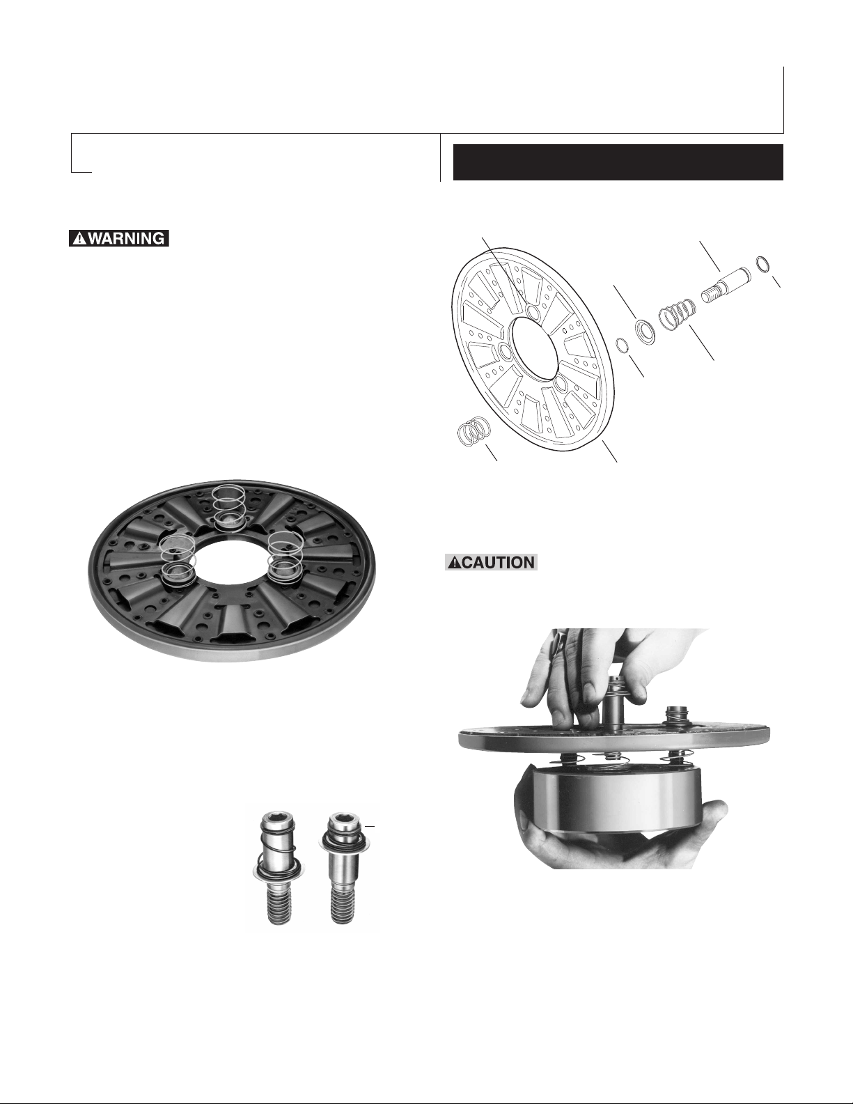
Autogap Installation for
Armature Boss
Straight Spring
(White)
Detent Spring
Retainer
Retainer
Ring
Detent
Spring
Drive Pin
Heavy
Spring
(Red)
Armature
Sizes 825-1525 Basic Brakes & Clutches
P-1366
819-0016
Failure to follow these
instructions may result in product damage,
equipment damage, and serious or fatal
injury to personnel.
Assembly Instructions
Step 1. Place straight springs (white) over
armature boss on back side of armature.
Installation Instructions
straight (white) springs and into threaded holes
in armature hub. (See Figure 3)
(See Figure 1)
Step 2. Compress heavy spring (red) against
retainer ring by sliding
detent spring towards
head of pin. (See Figure
2)
Step 3. Insert
assembled drive pins
through segmented side
of armature, through
(Figure 1)
(Figure 2)
(Figure 3)
Compressed
Be sure that straight white springs do not get
caught under shoulder of drive pins.
Step 4. Draw drive pins up tightly until shoulder
Warner Electric P-1366 • 800-825-9050
Page 2
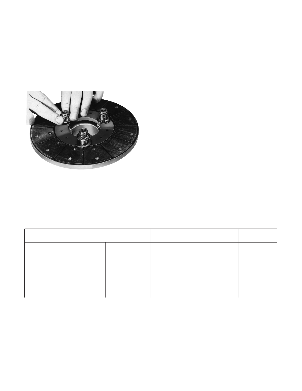
of pin is against face of hub (since threads are
class No. 3, pins may seem to bind).
Step 5. Check to see that the armature is
completely compressed against the face of the
hub. To set the autogap, slide the detent spring
retainers against the armature face.
(See Figure 4)
Step 6. Slide the armature and the hub with
taperlock bushing over the shaft until the face of
the armature contacts the face of the magnet or
rotor. Move armature assembly to provide a
clearance of 1/16 inch between the armature
face and magnet or rotor face.
The assembly should be checked by pressing
the armature into contact with the friction face
and then releasing the armature. The armature
should spring back approximately 3/64-inch.
This gap wilI be automatically maintained
throughout the life of the unit.
Note: During the assembly of the clutch or brake
components, the units must be checked for
concentricity and squareness to the shaft. This is
accomplished by using a dial indicator. The
following table gives the check points and
tolerances. (See Figure 5)
Note: This position must not be disturbed during
completion of assembly.
Figure 4
Primary Brake SF - Stationary
Unit PB Field Clutch
Part Magnet Armature Rotor Field Armature
Check
.010 T.I.R. .010 T.I.R. .006 T.I.R. .006 T.I.R. .006 T.I.R.
Concentricity Outside Drive Pilot Dia. Outside Drive
Diameter Pins I.D. Diameter Pins
.006 T. I. R. .006 T. I. R.
Squareness Outer Pole .006 T. I. R. Outer Pole .006 T.I.R.
of Face Face of Face Face
Figure 5 - Tolerance Table
Warner Electric • 800-825-9050 P-1366 • 819-0016
2
Page 3

B
A
C
D
1/2-13U NC-3A
THDS.
5/16"
1-9/32"
2-1/4"
.6185 Dia.
+.0005
-.0010
Drive Pins Should be Retained
with Sealant
Before installing the drive pins, apply a good
®
grade of thread sealant such as Loctite
, or
equivalent, to the threaded portion only.
Caution must be taken to prevent the sealant
from getting on the bearing surface of the pin.
Tighten all pins securely by inserting an Allen
wrench in the socket provided.
Machining Instructions for Gear, Sprocket, or Pulley
1. Chordal dimensions “A” or “C” must be held
for all chords between pin holes.
2. Drill 27/64 inch diameter holes to a sufficient
depth and tap for 1/2-13 NC-3A one inch
minimum full threads. Pin holes must be
square with plane of mounting surface and
magnet mounting.
3. Ream .500/.501 to a 3/8 inch depth and to
be concentric with tapped holes.
For Sizes 825 through 1525
Unit Size ABCD
825 3.085 ± .001 3.563 ± .001
1000 4.548 ± .002 5.252 ± .002
1225 4.155 ± .002 5.877 ± .002
1525 6.010 ± .002 8.500 ± .002
Warner Electric • 800-825-9050 P-1366 • 819-0016
3
Page 4

Warranty
Warner Electric LLC warrants that it will repair or replace (whichever it deems advisable) any
product manufactured and sold by it which proves to be defective in material or workmanship
within a period of one (1) year from the date of original purchase for consumer, commercial or
industrial use.
This warranty extends only to the original purchaser and is not transferable or assignable without
Warner Electric LLC’s prior consent.
Warranty service can be obtained in the U.S.A. by returning any defective product, transportation
charges prepaid, to the appropriate Warner Electric LLC factory. Additional warranty information
may be obtained by writing the Customer Satisfaction Department, Warner Electric LLC, 449
Gardner Street, South Beloit, Illinois 61080, or by calling 815-389-3771.
A purchase receipt or other proof of original purchase will be required before warranty service is
rendered. If found defective under the terms of this warranty, repair or replacement will be made,
without charge, together with a refund for transportation costs. If found not to be defective, you
will be notified and, with your consent, the item will be repaired or replaced and returned to you
at your expense.
This warranty covers normal use and does not cover damage or defect which results from
alteration, accident, neglect, or improper installation, operation, or maintenance.
Some states do not allow limitation on how long an implied warranty lasts, so the above limitation
may not apply to you.
Warner Electric LLC’s obligation under this warranty is limited to the repair or replacement of the
defective product and in no event shall Warner Electric LLC be liable for consequential, indirect,
or incidental damages of any kind incurred by reason of the manufacture, sale or use of any
defective product. Warner Electric LLC neither assumes nor authorizes any other person to give
any other warranty or to assume any other obligation or liability on its behalf.
WITH RESPECT TO CONSUMER USE OF THE PRODUCT, ANY IMPLIED WARRANTIES WHICH
THE CONSUMER MAY HAVE ARE LIMITED IN DURATION TO ONE YEAR FROM THE DATE OF
ORIGINAL CONSUMER PURCHASE. WITH RESPECT TO COMMERCIAL AND INDUSTRIAL
USES OF THE PRODUCT, THE FOREGOING WARRANTY IS IN LIEU OF AND EXCLUDES ALL
OTHER WARRANTIES, WHETHER EXPRESSED OR IMPLIED BY OPERATION OF LAW OR
OTHERWISE, INCLUDING, BUT NOT LIMITED TO, ANY IMPLIED WARRANTIES OF
MERCHANTABILITY OR FITNESS.
Some states do not allow the exclusion or limitation of incidental or consequential damages, so
the above limitation or exclusion may not apply to you. This warranty gives you specific legal
rights and you may also have other rights which vary from state to state.
Changes in Dimensions and Specifications
All dimensions and specifications shown in Warner Electric catalogs are subject to change without
notice. Weights do not include weight of boxing for shipment. Certified prints will be furnished
without charge on request to Warner Electric.
War ner Elect ric
31 Industrial Park Road • New Hartford, CT 06057
815-389-3771 • Fax: 815-389-2582
www.warnerelectric.com
P-1366 819-0016 8/11 Printed in USA
 Loading...