

Page 1
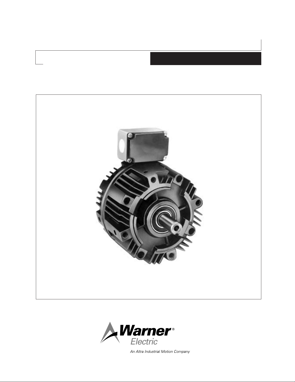
Conduit Box Kit No. 5370-101-042
for use with Electro Modules
P-1408
819-0344
Installation Instructions
Page 2
Make sure all power is turned
off to this equipment when installing. Failure
to follow these instructions may result in
product damage, equipment damage, and
serious or fatal injury to personnel.
Introduction
This Warner Electric conduit box is designed to
provide a proper enclosure for wiring terminations.
It conforms to the requirements of Underwriters
Laboratories under UL508, Industrial Control
Equipment.
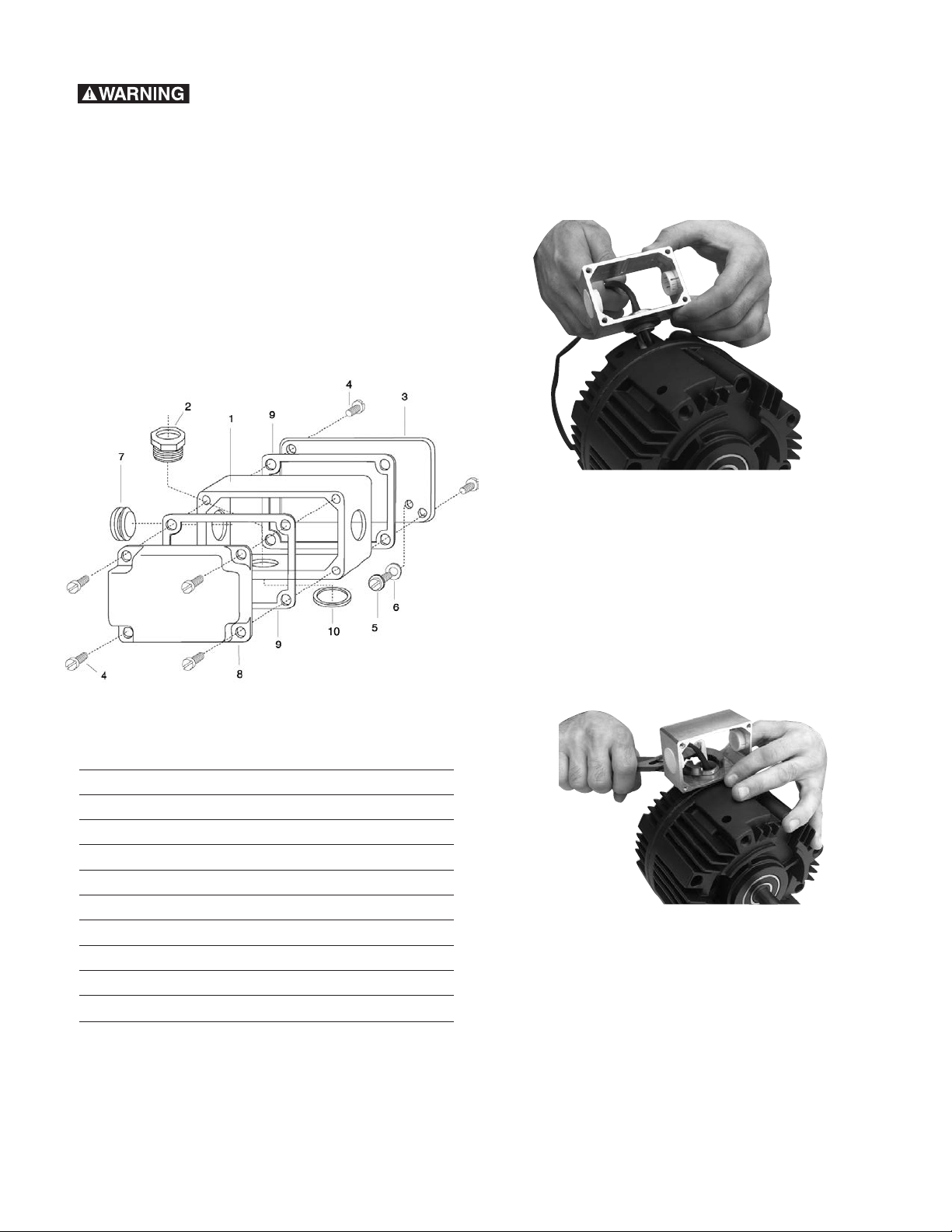
Assembly to Electro Module
1. Feed clutch/brake lead wires through tooth
washer (10) and bottom hole in conduit box (1)
and conduit box fitting (2). (See Figure 1)
Figure 1
Parts list for kit 5370-101-042
Item Quantity Part Name
11Conduit Box
21Conduit Box Fitting
31Cover Plate
46Pan Head Tapping Screw
51Hex. Washer Head Screw
61Ring Terminal
72Protective Plug
81Cover (Plastic)
92Gasket
10 1 Tooth Washer
Note: All screws are self tapping.
2. Insert conduit box fitting (2) through bottom
hole of conduit box and thread into tapped hole
of module housing. Tighten securely to hold
box in place. (See Figure 2)
Note: Hold wires to prevent twisting.
Figure 2
3. Assemble 1/2" flexible conduit fitting into
desired end of conduit box. Avoid using excess
force which could damage the mounting. Install
protective plug (fitting only) (7) into conduit box
hole which is not used. (See Figure 3)
Warner Electric • 800-825-9050 P- 1408 • 819-0344
2
Page 3

Figure 3
6. Electrical Connections
A. If external control is used, make wire
connections with wire nuts or appropriate
means in compliance with local electrical
codes. Use green self tapping screw (5)
and wire washer (6) for grounding.
(See Figure 6)
Important – Provide only D.C. power to the
clutch/brake. A.C. voltage will not allow unit
to function properly and damage may result.
4. Connect electric supply cable or flexible conduit
to the fitting installed in the conduit box. Rigid
conduit must not be connected directly to
the box as clutch/brake damage may
result. A minimum of 12 inches of flexible
cable or conduit is recommended.
(See Figure 4)
Figure 4
5. Connect back cover (3) to the conduit box with
two self tapping screws (4). (See Figure 5)
B. If CBC-150 control (not furnished) is used,
cut clutch/brake lead wires off to meet local
codes and make connections per CBC-150
installation instructions. Use green self
tapping screw (5) and wire washer (6) for
grounding. Mount control to box with four
self tapping screws (4).
Figure 6
7. If external control is used, install the black
plastic front cover (8) using the four self tapping
screws (4) furnished. (See Figure 7)
Figure 5
Figure 7
Warner Electric • 800-825-9050 P-1408 • 819-0344
3
Page 4

Warranty
Warner Electric LLC warrants that it will repair or replace (whichever it deems advisable) any
product manufactured and sold by it which proves to be defective in material or workmanship
within a period of one (1) year from the date of original purchase for consumer, commercial or
industrial use.
This warranty extends only to the original purchaser and is not transferable or assignable without
Warner Electric LLC’s prior consent.
Warranty service can be obtained in the U.S.A. by returning any defective product, transportation
charges prepaid, to the appropriate Warner Electric LLC factory. Additional warranty information
may be obtained by writing the Customer Satisfaction Department, Warner Electric LLC, 449
Gardner Street, South Beloit, Illinois 61080, or by calling 815-389-3771.
A purchase receipt or other proof of original purchase will be required before warranty service is
rendered. If found defective under the terms of this warranty, repair or replacement will be made,
without charge, together with a refund for transportation costs. If found not to be defective, you will
be notified and, with your consent, the item will be repaired or replaced and returned to you at
your expense.
This warranty covers normal use and does not cover damage or defect which results from
alteration, accident, neglect, or improper installation, operation, or maintenance.
Some states do not allow limitation on how long an implied warranty lasts, so the above limitation
may not apply to you.
Warner Electric LLC’s obligation under this warranty is limited to the repair or replacement of the
defective product and in no event shall Warner Electric LLC be liable for consequential, indirect,
or incidental damages of any kind incurred by reason of the manufacture, sale or use of any
defective product. Warner Electric LLC neither assumes nor authorizes any other person to give
any other warranty or to assume any other obligation or liability on its behalf.
WITH RESPECT TO CONSUMER USE OF THE PRODUCT, ANY IMPLIED WARRANTIES WHICH
THE CONSUMER MAY HAVE ARE LIMITED IN DURATION TO ONE YEAR FROM THE DATE OF
ORIGINAL CONSUMER PURCHASE. WITH RESPECT TO COMMERCIAL AND INDUSTRIAL
USES OF THE PRODUCT, THE FOREGOING WARRANTY IS IN LIEU OF AND EXCLUDES ALL
OTHER WARRANTIES, WHETHER EXPRESSED OR IMPLIED BY OPERATION OF LAW OR
OTHERWISE, INCLUDING, BUT NOT LIMITED TO, ANY IMPLIED WARRANTIES OF
MERCHANTABILITY OR FITNESS.
Some states do not allow the exclusion or limitation of incidental or consequential damages, so the
above limitation or exclusion may not apply to you. This warranty gives you specific legal rights and
you may also have other rights which vary from state to state.
Changes in Dimensions and Specifications
All dimensions and specifications shown in Warner Electric catalogs are subject to change without
notice. Weights do not include weight of boxing for shipment. Certified prints will be furnished
without charge on request to Warner Electric.
Warner Electric
31 Industrial Park Road • New Hartford, CT 06057
815-389-3771 • Fax: 815-389-2582
www.warnerelectric.com
P-1408 • 819-0344 8/11 Printed in USA
 Loading...