

Warner Electric 5219 Series, 5228 Series, 5218 Series, 5217 Series Installation & Operation Instructions
Page 1
P-1177-WE
819-0457
Residential, TG-2000 and
Commercial MagStop® Clutch/Brake
Installation & Operation Instructions
This Manual covers Magstop Product Families as outlined below:
Series Reference Name Torque Range
5217 Series RMS 60 & 80 ft-lb.
5218 Series CMS 175 & 200 ft-lb.
5219 Series TG 2000 105 & 125 ft-lb.
5228 Series CMS 250 225 & 250 ft-lb.
Page 2

Contents
Terminology............................3
MagStop® Components...................4
Mounting Requirements ................5-6
Anti-Rotation Examples ................7-13
Troubleshooting Checklist .............14-15
Electrical Evaluation.....................16
Series Reference Name Torque Range
5217 Series RMS 60 & 80 ft-lb.
5218 Series CMS 175 & 200 ft-lb.
5219 Series TG 2000 105 & 125 ft-lb.
5228 Series CMS 250 225 & 250 ft-lb.
This guide applies to Warner Electric MagStop
®
clutches and clutch/brakes used on power
equipment.
Residential, TG-2000, and Commercial MagStops
are available in a range of torque capacities. The
MagStop® name comes from the permanent
magnet brake (magnetic stopping) rather than
conventional spring activated mechanical brakes.
In addition to these general procedures, any
applicable OEM general and safety procedures
must also be followed.
Failure to follow these
instructions may result in product damage,
equipment damage, and serious or fatal
injury to personnel.
2 Warner Electric • 800-825-9050 P-1177-WE • 819-0457
Page 3

MagStop® Bearing Mounted Electric Clutch and Clutch/Brake Assemblies and Operation
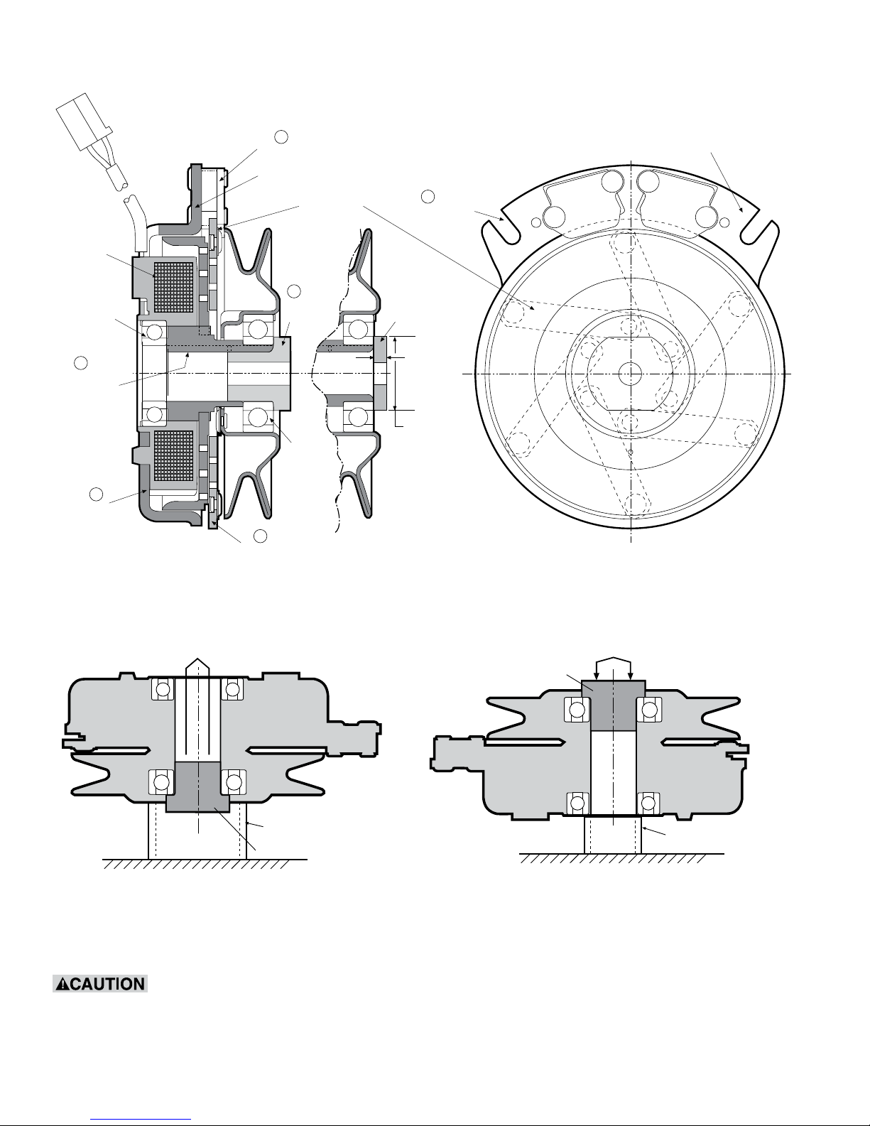
Components: (See Figure 1 on page 4.)
1. Rotor Assembly
Generally, the input of the clutch. Includes
a keyed hub which mates with the keyway
in the crank shaft. The rotor transmits the
torque from the crankshaft (driving shaft) to the
armature assembly (output).
2. Armature Assembly
Generally, the output of the clutch. Consists
of a disk, springs and pulley (or output flange).
With power applied the armature transmits
torque from the rotor to the driven load. Power
from the armature disk is transmitted to the
pulley or flange by means of the leaf springs.
3. Field Assembly
The clutch “power” source contains the coil
which generates magnetic attractive force.
4. Brake Poles
The two permanent magnets and plates ffixed
to the field shell provide the brake torque when
the clutch is disengaged. Brake poles are not
present if the assembly is a clutch only.
Optional Washer
A single .250 inch (6.35 mm) minimum thick steel
washer must be used between the clutch and the
crank shaft retaining bolt if the D-drive spacer is
not used.
A washer less than .250 inch
(6.35 mm) thick will deform and allow the
clamping load to be lost, resulting in damage
to the clutch and/or the crankshaft and
possible personal injury due to clutch
separating from the shaft. Multiple thinner
washers are not acceptable.
5. D-drive Spacer
A hub that is inserted into either armature or
field bearing (see Figure 2). The head has flats
that can be held with a wrench to prevent
rotation of the crankshaft when tightening
the mounting bolt (see Figure 5). This hub
also takes the place of the standard retaining
washer.
6. Anti-rotation Slot
Anti-rotation Slot (used with OEM’s anti-
rotation device) prevents MagStop from
rotation with crankshaft. If the field is bolted
rigidly or if its axial movement is restricted the
bearing in the field assembly will be improperly
loaded and may fail. Use OEM supplied antirotation.
Warner Electric • 800-825-9050 P-1177-WE • 819-0457 3
Page 4
MagStop® Components
Press
Press
Coil
Field
Bearing
1
Rotor
Assembly
3
Field
Assembly
Brake Poles
One piece
Field Assembly
2
Armature
Assembly
4
5
D-drive
Spacer
Armature
Bearing
Armature Leaf
Springs
Optional
Washer
.250 Inch
(6.35 mm)
Minimum
Washer
Thickness.
Washer
Diameter
Must Not
Exceed OD
of Bearing
Inner Race.
Figure 1
6
Anti-
Rotation
Slot
One Piece Field Assembly with
Integral Anti-Rotation Slots
Top View
from Pulley
D-drive Spacer Removal/Installation
D-drive Spacer
Support bearing outer race
D-drive Spacer
D-drive Spacer removal
Figure 2
D-drive Spacer installation
D-drive spacer may be installed on either end of clutch by OEM.
D-drive spacer must be removed or installed using an arbor press or equivalent. On
installation, opposite bearing INNER race must be supported or bearing damage may occur. On
removal, adjacent bearing OUTER race must be supported or bearing damage may occur.
Support bearing
inner race
4 Warner Electric • 800-825-9050 P-1177-WE • 819-0457
Page 5

REQUIREMENTS
for a Successful Clutch
Application/Installation
Critical Requirements
The two most important requirements for a successful clutch application or installation are:
1. Antirotation device must allow both axial
and radial free-play!
Failure to allow this free-play will result
in field bearing failure. The greater the
restriction the faster the bearing will
fail!
2. Mounting bolt torque to be
minimum of:
• 3/8 -24 UNF use Grade 8 bolt torqued
to 45-49 lb.-ft.
(Grade 5 bolt is unacceptable)
• 7/16-20 UNF Grade 5 or 8 bolt torqued
to 55-60 lb.-ft.
(Grade 5 or 8 bolt is
acceptable)
• M 10 X 1.50 Class 10.9 torqued to
55-65 N-m
Note: All values are for dry (unlubricated)
plated bolts, please consult fastener
manufacturer if any type of locking element
(thread lock compound, patch etc.) is to be
used.
Warner Electric • 800-825-9050 P-1177-WE • 819-0457 5
Failure to adhere to these requirements
will result in the failure of the clutch!
Page 6
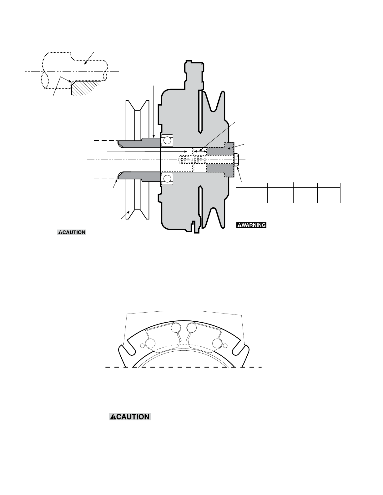
Mounting
Ground drive pulley or spacer
must be chamfered to clear this
radius on the engine shaft
shoulder.
Shaft
Engine Shaft
Note:
Must have faces parallel to each other
(within .003") and be perpendicular
to the bore.
Ground Drive Spacer
(or spacer if no ground
drive used)
round
Shaft end and
D-drive
spacer must
not touch
D-drive Spacer
Always bottom the clutch against a
flat surface; never against radius.
Anti-Rotation
Shaft
Shoulder
Ground
Drive
Pulley
Figure 3
Typical Engine Installation with Ground Drive Pulley
Anti-rotation Slots
Thread size Torque ft.lb. To rque N-m
3/8-24" UNF 45-49 ft.lb. 61-66 N-m
7/16-20" UNF 55-60 ft.lb. 75-81 N-m
M 10 X 1.50 40-48 ft.lb. 55-65 N-m
Note: All values are for dry (unlubricated) plated bolts,
please consult fastener manufacturer if any type of locking
element (thread lock compound, patch etc.) is to be used.
Failure to torque bolt
to requirements will
degrade clamping and
can allow the clutch to
separate from the
shaft, causing risk of
personal injury.
Grade Class
Grade 8
Grade 5 or 8
Grade 10.9
See Anti-Roatation Examples on pages 8-13
its axial movement is restricted, the bearing
in the field assembly will be improperly
loaded and may fail. Use only factory
installed anti-rotation device.
6 Warner Electric • 800-825-9050 P-1177-WE • 819-0457
Figure 4
If the field is bolted rigidly or if
Page 7

Incorrect
Do Not Orient So That
Bracket Will Bind In Slot
Do Not Bottom In Slot
Correct
.030 Min.
Loose Fit
.060 Min.,
Worst Case Stackup
Must Not Allow
Bottoming In Slot
Anti-Rotation Example
Attached To Frame
Incorrect
Do Not Orient So That
Bracket Will Bind In Slot
Do Not Bottom In Slot
Correct
.030 Min.
Loose Fit
.060 Min.,
Worst Case Stackup
Must Not Allow
Bottoming In Slot
Warner Electric • 800-825-9050 P-1177-WE • 819-0457 7
Page 8

Incorrect
Do Not Orient So That
Bracket Will Bind In Slot
Do Not Bottom In Slot
Correct
.030 Min.
Loose Fit
.060 Min.,
Worst Case Stackup
Must Not Allow
Bottoming In Slot
Anti-Rotation Example
Make Sure That This
Area Does Not Contact
Field Shell
.125 Min.
Incorrect
Do Not Orient So That
Bracket Will Bind In Slot
Do Not Bottom In Slot
Correct
.060 Min.,
Worst Case Stackup
Must Not Allow
Bottoming In Slot
.030 Min.
Loose Fit
8 Warner Electric • 800-825-9050 P-1177-WE • 819-0457
Page 9

Do Not Orient So That
Bracket Will Bind In Slot
.030 Min.
Loose Fit
.060 min.,
Worst Case Stackup
Must Not Allow
Bottoming In Slot
Correct
Do Not Bottom In Slot
Incorrect
Anti-Rotation Example
Make Sure That
Twisted Area Does
Not Contact
Field Shell
Beginning of Flat
.125 Min.
Incorrect
Do Not Orient So That
Bracket Will Bind In Slot
Do Not Bottom In Slot
Correct
.060 min.,
Worst Case Stackup
Must Not Allow
Bottoming In Slot
.030 Min.
Loose Fit
Warner Electric • 800-825-9050 P-1177-WE • 819-0457 9
Page 10

Anti-Rotation Example
.030 Min.
Loose Fit
Screw Must Be
Free To Move
10 Warner Electric • 800-825-9050 P-1177-WE • 819-0457
Page 11

Aircraft Cable,
.030 Min. Slack
Anti-Rotation Example
Aircraft Cable,
.030 Min. Slack
Warner Electric • 800-825-9050 P-1177-WE • 819-0457 11
Page 12

.030 Min.
Combined
Loose Fit
Anti-Rotation Example
.030 Min.
Combined
Loose Fit
12 Warner Electric • 800-825-9050 P-1177-WE • 819-0457
Page 13

.030 Min.
Loose Fit
.060 Min.,
Worst Case Stackup
Must Not Allow
Bottoming In Slot
Anti-Rotation Example
.030 Min.
Loose Fit
.060 Min.,
Worst Case Stackup
Must Not Allow
Bottoming In Slot
Warner Electric • 800-825-9050 P-1177-WE • 819-0457 13
Page 14

Troubleshooting Checklist
A. Symptom: Clutch will not engage
Problem Possible Causes Solution
Blown fuse • Low coil resistance • Replace with new MagStop unit
• Defective battery • Replace
• Faulty charging system • Repair or replace
• Bad wiring or connections, PTO switch • Repair or replace
Low voltage supply • Defective battery • Replace
(Less than 12 VDC at clutch) • Faulty charging system • Repair or replace
• Bad wiring or connectors, PTO switch • Repair or replace
Incorrect coil resistance • Damaged coil • Replace with new MagStop unit
(see Step 1, page 17)
Inadequate current supply • Broken clutch lead wire • Repair
• Faulty electrical system • Measure clutch coil resistance and
supply voltage at the clutch. If both
are correct, electrical system
is faulty. Repair or replace.
Rotor/armature airgap too large • Rotor/armature wear; end of usable life • Replace with new MagStop unit
(greater than .125 inch/3.18mm)
B. Symptom: Brake will not engage
Problem Possible Causes Solution
Armature/brake poles wore out • End of usable life • Replace with new MagStop unit
Contaminated friction surfaces • Engine oil leak on brake • Repair leak
• Replace with new MagStop unit
C. Symptom: Clutch slip
Problem Possible Causes Solution
Low voltage supply • Defective battery • Replace
(less than 12 VDC at clutch) • Faulty charging system • Repair or replace
• Bad wiring or connectors, PTO switch • Repair
Inadequate current supply • Broken clutch lead wire • Repair
• Faulty electrical system • Measure clutch coil resistance and
supply voltage at the clutch. If both
are correct, electrical system is
faulty. Repair or replace.
Overloaded clutch • Clogged deck, back spindle, etc. • Remove excess grass
• Replace spindle
Contaminated friction surfaces • Engine oil leak on clutch • Repair leak
• Replace with new MagStop unit
14 Warner Electric • 800-825-9050 P-1177-WE • 819-0457
Page 15

Troubleshooting Checklist (Continued)
D. Symptom: Noisy clutch/Vibration
Problem Possible Causes Solution
Failed bearing • Loose mounting (bolt not torqued properly) • Replace (see Mounting Figure 3, page 6)
• Field assembly movement restricted • Confirm proper Anti-rotation
(see Anti-rotation, Figure 4, page 6)
Adapter plate rattles against • Some noise is normal • If noise is excessive, repair or replace
anti-rotation pin anti-rotation device. (Follow OEM’s
Specifications. See Anti-rotation,
Figure 4, page 6).
Clutch loose on shaft • Loose mounting (bolt not torqued properly) • Tighten mounting bolt to specification.
See Mounting, Figure 3. page 6.
• Mounting bolt too long and bottoms • Use correct length bolt (see
in engine shaft before clamping clutch Mounting page 6, Figure 3)
• Mounting washer too thin and deforms • See Figure 1 and Warning on page 4.
when bolt is tightened.
• Shaft bottoms on D-drive • Use proper spacer (see Mounting page 6)
Clutch not mounted square • Ground Drive Spacer mounting shoulder • Replace
not squared. See Mounting Figure 3.
• Clutch integral key hitting end of keyway • Space clutch away from radius in shaft
in engine shaft keyway.
• Incorrect or no chamfer on ground • Increase chamfer on ground drive spacer.
drive spacer. See Caution, Figure 3, page 6.
Broken Spring • Loose mounting • Replace clutch
A clutch with broken rivets or springs may separate from the shaft and cause personal injury.
Burnishing Procedure when installing a
new MagStop® Clutch/Brake
This procedure should be performed with the load
attached (mowing deck, snowblower,
pump etc.)
2. Let load come to a full stop then engage
again.
3. Repeat these procedures (1 and 2)
Note: Do NOT add additional load
(e.g. cutting grass).
10 times. After burnish procedure is
complete, to maximize deck drive train
1. Run engine at full throttle and engage load
life, always engage clutch at half throttle.
bringing load to full speed then disengage
load.
Warner Electric • 800-825-9050 P-1177-WE • 819-0457 15
Page 16

Electrical Evaluation
Step 1. How to Measure Clutch Coil resistance
(See Figure 5)
1. Turn engine and PTO switch off.
2. Disconnect clutch at clutch connector.
3. Select meter setting for ohm reading.
4. Connect meter leads to clutch.
5. Check meter reading and refer to the chart
below for correct clutch resistance reading.
(values are @ 68°F.)
If reading falls in acceptable range proceed
to step 2, if not replace the clutch.
Step 2. Measure the supply voltage at the clutch
(See Figure 6)
1. Turn engine off.
2. Connect meter leads at the clutch connector.
3. Select meter setting for voltage reading.
4. Make sure wires will not become entangled
in rotating components of clutch.
5. Start engine and engage PTO switch.
6. Measure voltage across the leads at
the connectors.
7. Voltage should be 12-14 volts DC. If clutch
still fails to operate, replace clutch.
8. If voltage is not within 12-14 volt range
consult EOM’s service manual.
Meter
Figure 5
Resistance Measurement
Table 1
Resistance
Model Torque Rating
(ft-lb.) Nom. NM Nom. (ohms)
MS - 60 60 ft-lb. 81 NM 6.59 - 7.28
MS - 80 AL 80 ft-lb. 108 NM 2.86 - 3.17
MS - 80 CU 80 ft-lb. 108 NM 3.36 - 3.71
TG - 105 105ft-lb. 142 NM 2.89 - 3.20
TG - 125 125 ft-lb. 169 NM 2.65 - 2.92
CMS - 175 175 ft-lb. 237 NM 2.34 - 2.59
CMS - 200 200 ft-lb. 271 NM 1.74 - 1.93
CMS - 225 225 ft-lb. 305 NM 1.66 - 1.83
CMS - 250 250 ft-lb. 339 NM 1.71 - 1.89
at 68-70° F
Note: If bench tested with 12 volts applied,
armature may not pull away from
brakepoles. Rotational motion is
required to engage clutch.
Meter
Figure 6
Voltage Measurement
16 Warner Electric • 800-825-9050 P-1177-WE • 819-0457
Page 17

Re-gap Adjustment Procedure
When to remove shim:
When clutch has worn to the extent that the
existing air-gap is too large to allow for complete
clutch engagement (clutch may engage easily
when cold but has problems engaging when hot),
brake shim can be removed to restore air gap and
allow the clutch to continue to function.
(With engine off, key removed and clutch
disengaged)
Component Identification Reference
Brake PoleRe-gap ShimRotor Armature
Procedure:
Consult the operator’s manual for all related
procedures & safety practices.
Using a pneumatic line, blow out any debris from
under the brake pole and around the aluminum
spacers (Figure 2).
Figure 2
Check the air gap between rotor & armature with
feeler gage. If the gap is less than 0.70”, then
follow the trouble shooting procedure outlined on
pages 14, 15 and 16 of this installation trouble
shooting guide. If the air gap is over 0.70”,
proceed with procedure outline below (Figure 3).
Brake SpacerBrake Fastener
Figure 1
Warner Electric • 800-825-9050 P-1177-WE • 819-0457 17
Field Shell
Be certain that the gap between the rotor and
armature face is greater than .070 prior to shim
removal.
Figure 3
Page 18

Re-gap Adjustment Procedure (Continued)
1. Loosen both brake mounting bolts ½ to 1 full
turn as shown below (Figure 4).
Note: Do not remove brake pole from field shell/
armature – brake pole tracks match with
clutch off and brake on and need to
continue to match after shim is removed to
ensure proper brake torque.
Figure 4
2. Using needle nose pliers, or by hand, take hold
of the tab and remove shim (Figure 5).
5. Confirm that a minimum air gap of .015 is
present between rotor and armature face at
both ends of the brake pole using a feeler gage
as shown (Figure 6).
Figure 6
Figure 5
3. Using a pneumatic line, blow out any debris
from under the brake pole and around the
aluminum spacers (Figure 2).
4. Re-torque each bolt (M6 X 1) to 10 ft-lbs
+/-.5ft-lbs.
Figure 7
6. If no gap is present, or one smaller than .015,
the clutch must be replaced (Figure 7).
7. If adequate gap is present, start engine and
cycle clutch 10 consecutive times.
Refer to burnish procedure on page 15.
18 Warner Electric • 800-825-9050 P-1177-WE • 819-0457
Page 19

Re-gap Adjustment Procedure (Continued)
8. PERFORM SAFTY CHECK:
a. Be sure to observe deck from position
on mower seat to be certain deck is not
engaged with PTO switch “off” or clutch deenergized, with engine running
If clutch was removed from the tractor be sure to
torque the mounting bolt to the specified torque
value:
Thread Size Grade Class Torque lb-ft Torque N-M
3/8-24” UNF Grade 8 45-49 ft.lb.. 61-66 N-m
7/16-20” UNF Grade 5 or 8 55-60 ft.lb. 75-81 N-m
M 10 X 1.50 Grade 10.9 40-48 ft.lb. 55-65 N-m
Note: All values are for dry (unlubricated) plate
bolts, please consult fastener manufacturer
if any type of locking elements (thread lock
compound, patch etc.) is to be used.
Figure 8
Warner Electric • 800-825-9050 P-1177-WE • 819-0457 19
Mounting Bolt
Page 20

Warranty
Warner Electric LLC warrants that it will repair or replace (whichever it deems advisable) any product
manufactured and sold by it which proves to be defective in material or workmanship within a period of one (1)
year from the date of original purchase for consumer, commercial or industrial use.
This warranty extends only to the original purchaser and is not transferable or assignable without Warner Electric
LLC’s prior consent.
Warranty service can be obtained in the U.S.A. by returning any defective product, transportation charges
prepaid, to the appropriate Warner Electric LLC factory. Additional warranty information may be obtained by
writing the Customer Satisfaction Department, Warner Electric LLC, 449 Gardner Street, South Beloit, Illinois
61080, or by calling 815-389-3771.
A purchase receipt or other proof of original purchase will be required before warranty service is rendered. If
found defective under the terms of this warranty, repair or replacement will be made, without charge, together
with a refund for transportation costs. If found not to be defective, you will be notified and, with your consent, the
item will be repaired or replaced and returned to you at your expense.
This warranty covers normal use and does not cover damage or defect which results from alteration, accident,
neglect, or improper installation, operation, or maintenance.
Some states do not allow limitation on how long an implied warranty lasts, so the above limitation may not apply
to you.
Warner Electric LLC’s obligation under this warranty is limited to the repair or replacement of the defective
product and in no event shall Warner Electric LLC be liable for consequential, indirect, or incidental damages of
any kind incurred by reason of the manufacture, sale or use of any defective product. Warner Electric LLC neither
assumes nor authorizes any other person to give any other warranty or to assume any other obligation or liability
on its behalf.
WITH RESPECT TO CONSUMER USE OF THE PRODUCT, ANY IMPLIED WARRANTIES WHICH THE
CONSUMER MAY HAVE ARE LIMITED IN DURATION TO ONE YEAR FROM THE DATE OF ORIGINAL
CONSUMER PURCHASE. WITH RESPECT TO COMMERCIAL AND INDUSTRIAL USES OF THE PRODUCT,
THE FOREGOING WARRANTY IS IN LIEU OF AND EXCLUDES ALL OTHER WARRANTIES, WHETHER
EXPRESSED OR IMPLIED BY OPERATION OF LAW OR OTHERWISE, INCLUDING, BUT NOT LIMITED TO,
ANY IMPLIED WARRANTIES OF MERCHANTABILITY OR FITNESS.
Some states do not allow the exclusion or limitation of incidental or consequential damages, so the above
limitation or exclusion may not apply to you. This warranty gives you specific legal rights and you may also have
other rights which vary from state to state.
Changes in Dimensions and Specications
All dimensions and specifications shown in Warner Electric catalogs are subject to change without notice.
Weights do not include weight of boxing for shipment. Certified prints will be furnished without charge on request
to Warner Electric.
www.warnerelectric.com
31 Industrial Park Road
New Hartford, CT 06057
815-389-3771
P-1177-WE 819-0457 9/18
4578 East Park 30 Drive
Columbia City, IN 46725
260-244-6183
 Loading...