

Page 1
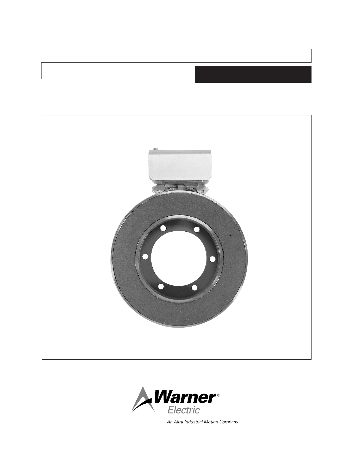
Conduit Box Kit No. 5200-101-011
P-1392
819-0199
Installation Instructions
Page 2
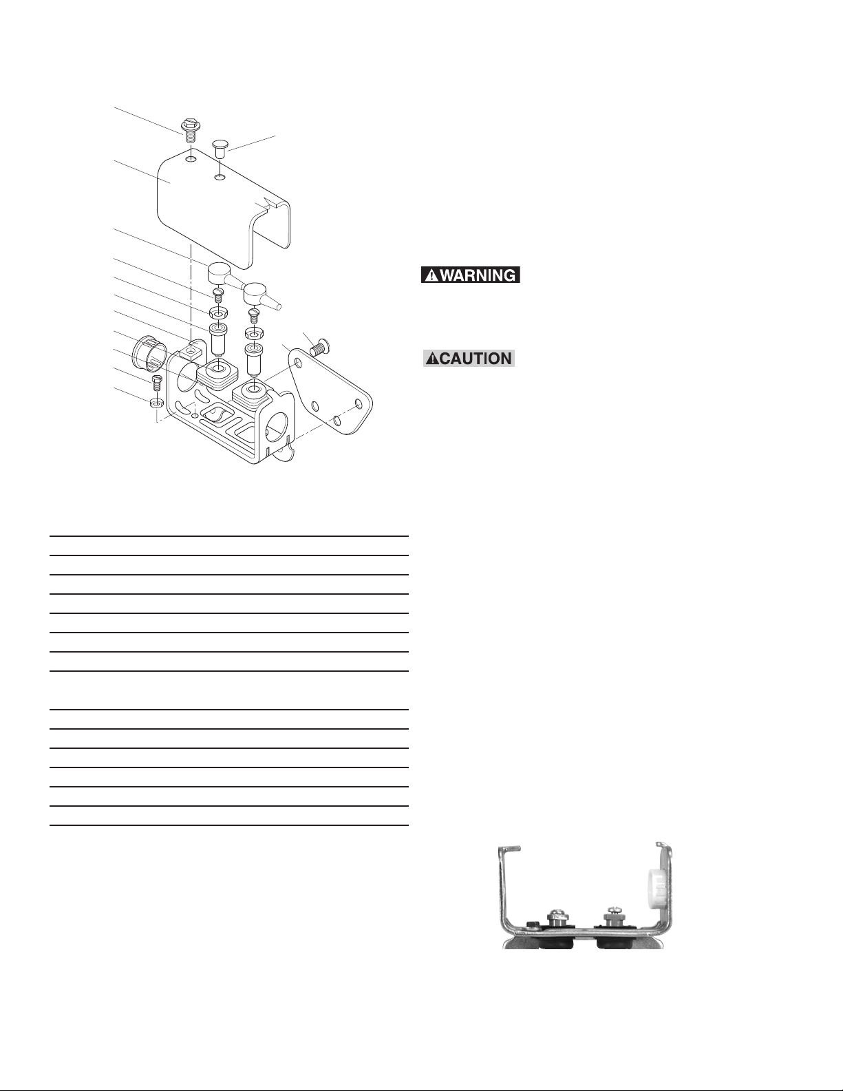
11
10
*7
*9
*9-1
6
3
5
4
8
8-1
12
2
1
Components
Parts List for kit 5200-101-011
Introduction
Conduit box kit No. 5200-101-011 plus field/
magnet terminal accessory kit, contains all
components needed to assemble a conduit box
for PB-825, 1000, 1225, 1525, EB-825, 1000,
1225, EC-1000, 1225 clutches and brakes. This
conduit box will provide a proper means for wiring
terminations and conforms to the requirements of
Underwriters Laboratories.
Failure to follow these
instructions may result in product damage,
equipment damage, and serious or fatal injury
to personnel.
Do not connect rigid conduit
directly to the conduit box. A minimum of 12”
of flexible liquid tight conduit or other suitable
flexible wiring with appropriate fittings is
required. Flexible conduit is required to prevent
side loading of bearing on bearing mounted
clutches and brakes and possible deformation
of the conduit box or clutch/brake components
during assembly.
Item Quantity Part Name
11 Bracket
24 Screw, Flat Head
31 Box, Conduit
41 Plug, Protective
52 Grommet, Wire
62 Spacer, Terminal
*7 2 Cap, Terminal
Step 1
Assemble a customer supplied flexible wiring
connector into the desired end of the conduit box
(3). Press protective plug (4) into unused conduit
hole.
Thread green washer head hex screw (8) into round
hole in base of conduit box. Place terminal ring (8-1)
over screw before inserting.
81 Screw, Hex, Washer Head
Green
8-1 1 Ring, Terminal
*9 2 Screw, No. 8 Brass
*9-1 2 Ring, Terminal
10 1 Cover
11 1 Screw, Hex, Washer Head
Snap two wire grommets (5) into square holes in
conduit box base. The grommet crowns should be
toward the outside of the box and the rubber
flanges should be on both sides of the conduit box.
Push two terminal spacers (6) through rubber
grommets. (See Figure 1)
12 1 Plug, Protective
*Item 7 - Cap, Terminal, Item 9-1 - Ring, Terminal, and Item 9 - Screw, No.
8 Brass, are provided in terminal Accessory Kit 5311-101-001.
Note: All mounting screws are self-tapping.
Figure 1
2
Warner Electric • 800-825-9050 P-1392 • 819-0199
Page 3

Step 2
Follow A or B, depending on magnet mounting:
A. Inside Mounted Magnets/Fields and O.M.825
Fasten bracket (1) to the back of the
magnet/field by assembling two No. 10-32
undercut flat head machine screws (2) into the
holes provided. Screws are self-tapping, holes in
the field/magnet are not threaded. (See Figure 2)
Figure 2 - Inside Mount
B. Outside Mounted Magnets
Bracket (1) and two of the four flat head machine
screws (2) are not required on these
field/magnets. (See Figure 3)
Figure 4
Step 4
Connect electric supply cable to the fitting installed
on the conduit box. If an external power supply is
furnishing DC current to the clutch or brake,
proceed to Step 5 and skip Step 6. If a Warner
Electric CBC-100 power supply is being installed in
the conduit box, skip Step 5 and proceed to Step 6.
Step 5 - DC Connection
Slide one terminal cap (7) onto each of the two
supply conductors, small end first. Connect the two
supply conductors (with rubber caps) to the magnet
or field terminals using two No. 8 brass screws (9)
and ring terminals (8-1). The stripped wires can
wrap around the screw between the terminal ring
and the screw head or other ring type terminals may
be used. Electrical supply connections must
conform to local electrical codes. Install plug (12)
into cover hole.
Step 6 - AC Connection
When a CBC-100 power supply is used, refer to
installation sheet P-266 provided with the CBC-100,
following instructions carefully. To mount the CBC100 to the conduit box, place the control into the
cover so that curved surfaces conform, line up the
cover hole with the control mounting hole and
fasten with screw provided in the mounting kit.
Figure 3 - Outside Mount
Connections to the magnet or field terminals are
as outlined in Step 5.
Step 3
Mount conduit box to the bracket on the inside
mount magnets/fields, or to the mounting flange on
outside mount magnets. Thread terminal spacers
into field/magnet before fastening conduit box to
bracket. Do not over tighten, excessive torque will
pull thread insert out of thefield/magnet. The conduit
Step 7
A ground wire is recommended for grounding of the
conduit box and brake magnet or clutch field.
Connect this wire with the green ground screw (8) to
the hole in the floor of the box. Consult local codes
regarding grounding requirements.
box must be on the front side of the bracket.
Secure the box with two No. 10-32 undercut flat
head machine screws (2). (See Figure 4)
Step 8
Install cover (10) by sliding the slot in the cover over
the tab on one end of the conduit box and secure
the cover on the opposite end with one No. 10-32
Warner Electric • 800-825-9050 P-1392 • 819-0199
hex washer head screw (11).
3
Page 4

Warranty
Warner Electric LLC warrants that it will repair or replace (whichever it deems advisable) any
product manufactured and sold by it which proves to be defective in material or workmanship within
a period of one (1) year from the date of original purchase for consumer, commercial or industrial
use.
This warranty extends only to the original purchaser and is not transferable or assignable without
Warner Electric LLC’s prior consent.
Warranty service can be obtained in the U.S.A. by returning any defective product, transportation
charges prepaid, to the appropriate Warner Electric LLC factory. Additional warranty information may
be obtained by writing the Customer Satisfaction Department, Warner Electric LLC, 449 Gardner
Street, South Beloit, Illinois 61080, or by calling 815-389-3771.
A purchase receipt or other proof of original purchase will be required before warranty service is
rendered. If found defective under the terms of this warranty, repair or replacement will be made,
without charge, together with a refund for transportation costs. If found not to be defective, you will
be notified and, with your consent, the item will be repaired or replaced and returned to you at your
expense.
This warranty covers normal use and does not cover damage or defect which results from
alteration, accident, neglect, or improper installation, operation, or maintenance.
Some states do not allow limitation on how long an implied warranty lasts, so the above limitation
may not apply to you.
Warner Electric LLC’s obligation under this warranty is limited to the repair or replacement of the
defective product and in no event shall Warner Electric LLC be liable for consequential, indirect,
or incidental damages of any kind incurred by reason of the manufacture, sale or use of any
defective product. Warner Electric LLC neither assumes nor authorizes any other person to give any
other warranty or to assume any other obligation or liability on its behalf.
WITH RESPECT TO CONSUMER USE OF THE PRODUCT, ANY IMPLIED WARRANTIES WHICH
THE CONSUMER MAY HAVE ARE LIMITED IN DURATION TO ONE YEAR FROM THE DATE OF
ORIGINAL CONSUMER PURCHASE. WITH RESPECT TO COMMERCIAL AND INDUSTRIAL USES
OF THE PRODUCT, THE FOREGOING WARRANTY IS IN LIEU OF AND EXCLUDES ALL OTHER
WARRANTIES, WHETHER EXPRESSED OR IMPLIED BY OPERATION OF LAW OR
OTHERWISE, INCLUDING, BUT NOT LIMITED TO, ANY IMPLIED WARRANTIES OF
MERCHANTABILITY OR FITNESS.
Some states do not allow the exclusion or limitation of incidental or consequential damages, so the
above limitation or exclusion may not apply to you. This warranty gives you specific legal rights and
you may also have other rights which vary from state to state.
Changes in Dimensions and Specifications
All dimensions and specifications shown in Warner Electric catalogs are subject to change without
notice. Weights do not include weight of boxing for shipment. Certified prints will be furnished
without charge on request to Warner Electric.
Warner Electric
31 Industrial Park Road • New Hartford, CT 06057
815-389-3771 • Fax: 815-389-2582
www.warnerelectric.com
P-1392 • 819-0199 8/11 Printed in USA
 Loading...