

Page 1
Autogap
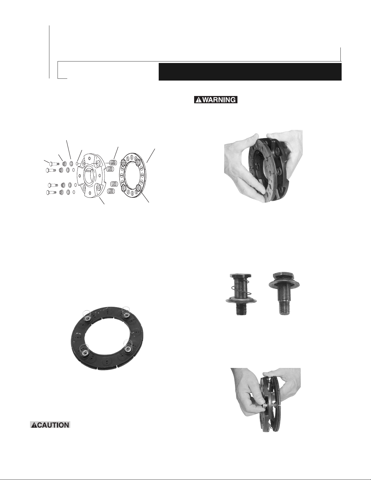
Drive Pin
Conical
Spring
Retainer
Detent
Spring
Straight
Spring
Armature
Armature Boss
*Armature Hub
& 650 Basic Brakes & Clutches
™
Installation for Sizes 475
5181-101-010
Part Number
P-1380
819-0111
Assembly Instructions
Brake or Clutch Coupling Installation
* The size 475 armature will differ in appearance from
the one shown, but the assembly procedure is the
same.
Installation Instructions
Failure to follow these instructions
may result in product damage, equipment
damage, and serious or fatal injury to personnel.
Figure 2
Step 3
Compress conical spring against retainer ring by
sliding detent spring towards head of pin. (All 4 pins)
(Figure 3)
Step 1
Place straight springs over armature bosses on back
side of armature. (Figure 1)
Figure 1
Step 2
Place armature hub over straight springs assembled
in Step 1. (Figure 2)
grooves in armature hub.
Straight springs must fit into
Figure 3
Step 4
Insert assembled drive pins through armature hub,
through straight springs and into threaded holes in
back side of armature. Drive pins require application
of Grade “AA” Loctite
®
‚ Sealant on threads. (Figure 4)
Figure 4
Warner Electric 800-825-9050
Page 2
Step 5
Drive
Pin
Conical
Spring
Straight
Spring
Armature
Armature
Hub
Detent
Spring
Retainer
Armature
Boss
Draw drive pins up tightly until shoulder of pin is
against face of armature boss, (since threads are
class No. 3 fit, pins may seem to bind).
Step 6
Compress the retainers against the armature hub and
check to see that the armature hub is held tightly to
the armature bosses.
NOTE: This position must not be disturbed during
completion of assembly.
Step 7
Slide the armature and armature hub with taperlock
bushing over the shaft. Place the face of the armature
approximately 1/32" from the magnet face and secure
the taper lock bushing to the shaft. This gap will be
automatically maintained throughout the life of the
unit. The unit should be checked for concentricity and
squareness to the shaft by means of a dial indicator.
The unit should be concentric to the shaft within .010
T.I.R. and square to the shaft within .006 T.I.R.
(Figure 5)
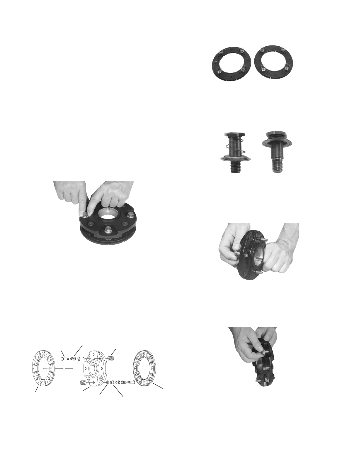
Step 1
Place straight springs over armature bosses on back
side of both armatures. (Figure 1)
Figure 1
Step 2
Compress conical spring against retainer ring by
sliding detent spring towards head of pin. (All 8 pins)
(Figure 2)
Figure 2
Step 3
Insert (4) of the compressed drive pins through the
armature hub so that the threaded end of the pins
Figure 5
Assembly Instructions Clutch Brake
Coupling Installation Size 650 Only
come through on the side of the armature hub with
the groove around the hole. (Figure 3)
Figure 3
Step 4
Repeat Step 3 above for the remaining (4) drive pins
inserting them from opposite side of armature hub
Warner Electric • 800-825-9050 P-1380 • 819-0111
2
Page 3
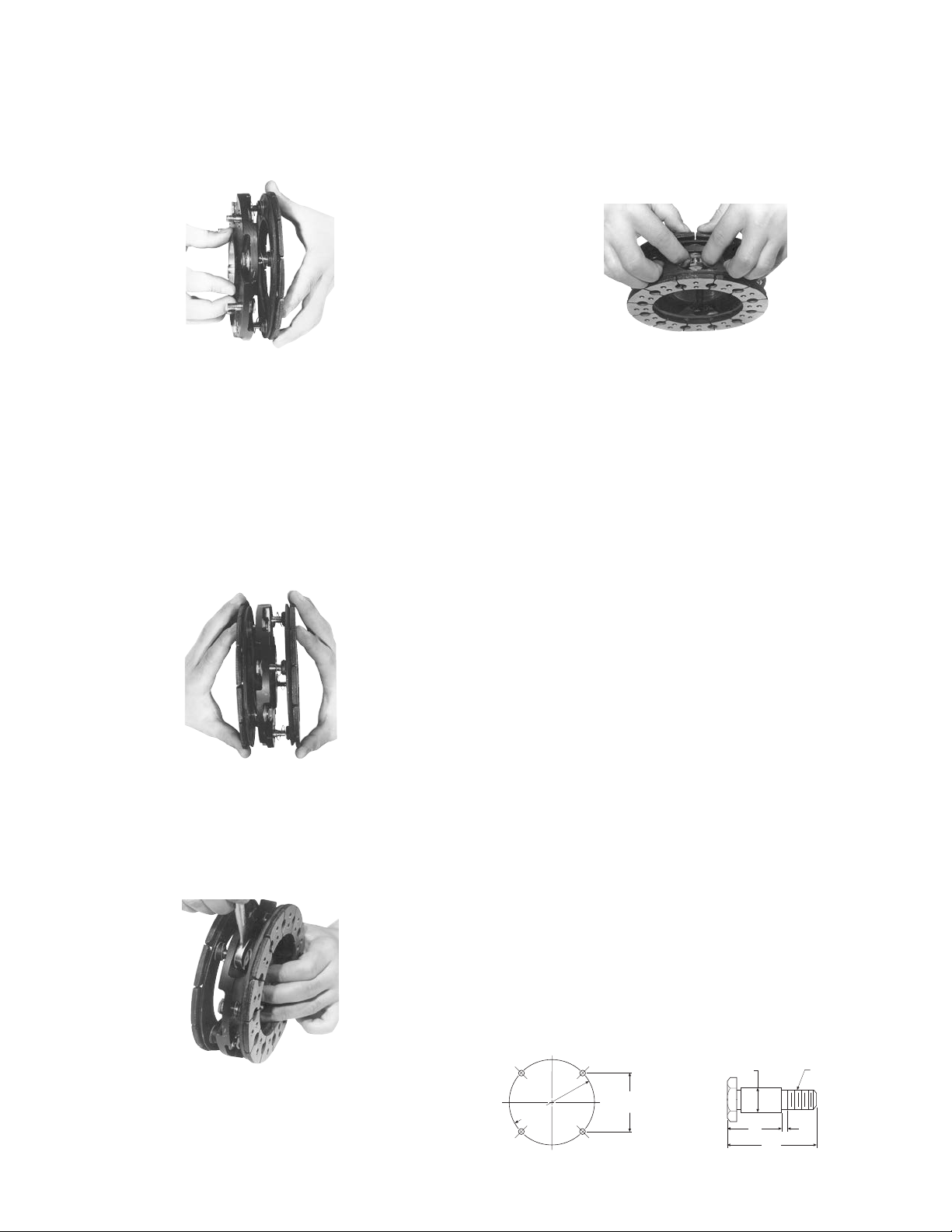
through remaining (4) holes. (Figure 4)
3.624
± .001
Chordal
5.125 ± .001
Bolt Circle
.3665 ± .0005 DIA.
5/16 - 24 UNF - 3A
Threads
7/8 1/16
1-3/8
Figure 4
Step 5
Holding the pins in position, place the armature hub
over one armature. NOTE: Make sure that the
straight springs on the armature bosses fit into the
grooves in the armature hub. Drive pins require
application of Grade “AA” Loctite®‚ sealant on
threads. (Figure 5)
Figure 5
Step 6
Draw these (4) drive pins up tightly until shoulder of
pin is against face of armature boss (since threads
are class No. 3 fit, pins may seem to bind).
Step 7
Place the armature hub and armature assembled in
step 5 & 6 over the remaining armature. NOTE: Make
sure that the four remaining straight springs on the
class No. 3 fit, pins may seem to bind). NOTE:
Rotate tightening of drive pins, tightening each
drive pin a few turns at a time. (Figure 7)
Figure 7
Step 9
Compress one of the armatures and armature hub
together until the armature hub bottoms on the
armature boss. Slide the retainer, on each pin, down
tightly against the armature hub. Turn the assembly
over and repeat this procedure for remaining
armature. NOTE: This position must not be
disturbed during completion of assembly. (Figure 8)
Figure 8
Step 10
Slide the assembly with taperlock bushing over the
shaft. Place the face of the armature approximately
1/32" from the brake magnet face and fix the
taperlock bushing to the shaft.
Step 11
Place the clutch magnet approximately 1/32" from
the armature face, and tighten the taperlock bushing
to the shaft. The unit should then be checked for
concentricity and squareness to the shaft by means
of a dial indicator. The unit should be concentric to
the shaft within .010 T.I.R. and square to the shaft
Machining Instructions for Gear,
Sprocket, or Pulley–Size 650 Only
armature bosses fit into the grooves in the armature
hub. Drive pins require application of Grade “AA”
®
Loctite
‚ sealant on threads. (Figure 6)
Figure 6
Step 8
Draw drive pins up tightly until shoulder of pin is
against face of armature boss, (since threads are
Warner Electric • 800-825-9050 P-1380 • 819-0111
As in the case of a clutch, the customer may wish to
mount the armature to his pulley, hub, etc. The above
dimensions must be followed for adaptation to the
armature.
1. The chordal dimension must be held for all chords
between pin holes.
2. Sleeve bearings (Oilite Bronze) must be provided
in the holes of pulley or hub with an I.D. of .376
± .001 at the chordal and bolt circle dimensions
shown above.
3. The drive pins must be square with plane of
mounting surface and magnet within .006 T.I.R.
Our standard armature hub may be used for the
mounting of a gear, sprocket or pulley.
3
Page 4

Warranty
Warner Electric LLC warrants that it will repair or replace (whichever it deems advisable) any
product manufactured and sold by it which proves to be defective in material or workmanship within a
period of one (1) year from the date of original purchase for consumer, commercial or industrial use.
This warranty extends only to the original purchaser and is not transferable or assignable without Warner
Electric LLC’s prior consent.
Warranty service can be obtained in the U.S.A. by returning any defective product, transportation charges
prepaid, to the appropriate Warner Electric LLC factory. Additional warranty information may be obtained
by writing the Customer Satisfaction Department, Warner Electric LLC, 449 Gardner Street, South Beloit,
Illinois 61080, or by calling 815-389-3771.
A purchase receipt or other proof of original purchase will be required before warranty service is
rendered. If found defective under the terms of this warranty, repair or replacement will be made, without
charge, together with a refund for transportation costs. If found not to be defective, you will be notified
and, with your consent, the item will be repaired or replaced and returned to you at your expense.
This warranty covers normal use and does not cover damage or defect which results from
alteration, accident, neglect, or improper installation, operation, or maintenance.
Some states do not allow limitation on how long an implied warranty lasts, so the above limitation may
not apply to you.
Warner Electric LLC’s obligation under this warranty is limited to the repair or replacement of the
defective product and in no event shall Warner Electric LLC be liable for consequential, indirect,
or incidental damages of any kind incurred by reason of the manufacture, sale or use of any defective
product. Warner Electric LLC neither assumes nor authorizes any other person to give any other warranty
or to assume any other obligation or liability on its behalf.
WITH RESPECT TO CONSUMER USE OF THE PRODUCT, ANY IMPLIED WARRANTIES WHICH THE
CONSUMER MAY HAVE ARE LIMITED IN DURATION TO ONE YEAR FROM THE DATE OF ORIGINAL
CONSUMER PURCHASE. WITH RESPECT TO COMMERCIAL AND INDUSTRIAL
USES OF THE PRODUCT, THE FOREGOING WARRANTY IS IN LIEU OF AND EXCLUDES ALL OTHER
WARRANTIES, WHETHER EXPRESSED OR IMPLIED BY OPERATION OF LAW OR
OTHERWISE, INCLUDING, BUT NOT LIMITED TO, ANY IMPLIED WARRANTIES OF
MERCHANTABILITY OR FITNESS.
Some states do not allow the exclusion or limitation of incidental or consequential damages, so the
above limitation or exclusion may not apply to you. This warranty gives you specific legal rights and you
may also have other rights which vary from state to state.
Changes in Dimensions and Specifications
All dimensions and specifications shown in Warner Electric catalogs are subject to change without notice. Weights do not include weight of boxing for shipment. Certified prints will be furnished without
charge on request to Warner Electric.
Warner Electric
31 Industrial Park Road • New Hartford, CT 06057
815-389-3771 • Fax: 815-389-2582
www.warnerelectric.com
P-1380 • 819-0111 11/11 Printed in USA
An Altra Industrial Motion Company
 Loading...