

Page 1
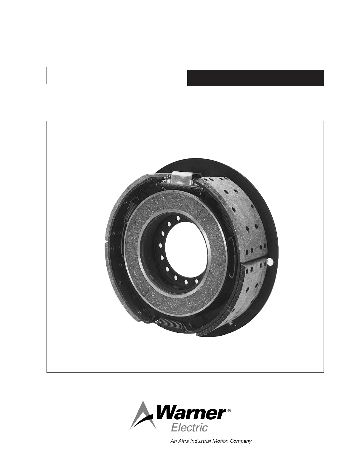
16-1/2" x 5" Shoe Brake
#1305-2 Brake, Complete Pair
P-1384
819-0116
Installation Instructions
Page 2
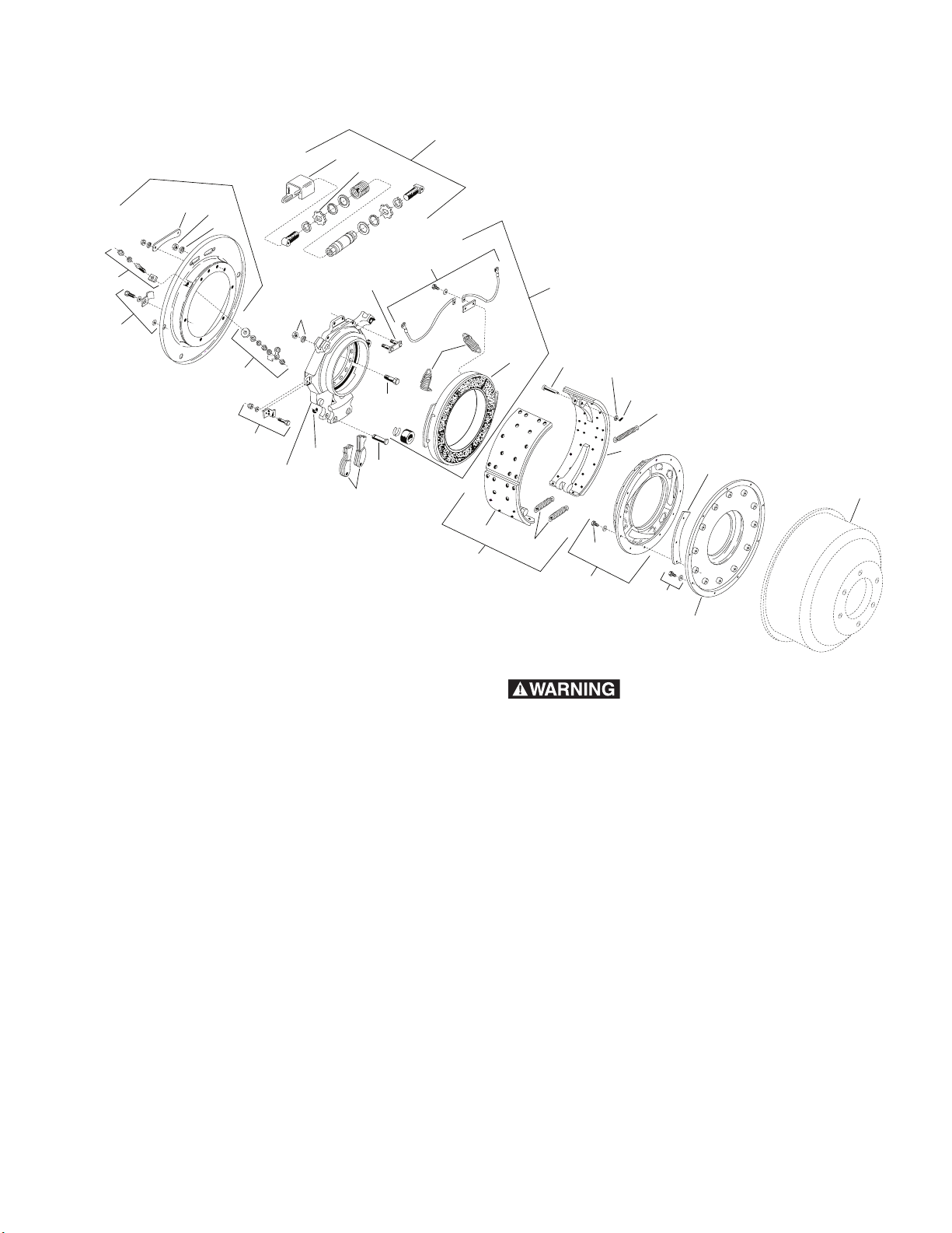
Service Parts and Kits
14
11
11
12
13
14-3
7-1
7-2
7
14-1
14-2
12-4
13
12-3
12-1
12-2
13
10-1
10-3
10-2
9
14-5
14-6
14-4
6
6-1
6-2
6-3
6-1
5
5-1
3
4
2
31
12
7-0
Kit No. 1305-2
Complete Axle Kit
Kit consists of:
1-R.H. Brake Assembly
1-L.H. Brake Assembly
1 - Armature R.H.
1-Armature L.H.
2-Armature Adapter Assemblies
with Grease Guard
1-Brake Mounting Accessory
1-Adapter Mounting Accessory
1-Armature Mounting Accessory
Warner Electric • 800-825-9050 P-1384 • 819-0116
2
instructions may result in product damage,
equipment damage, and serious or fatal injury
to personnel.
General Note
It is suggested that, because of the size and weight of
the components of this brake, the complete assembly
be removed from the vehicle to facilitate handling
while replacing parts.
Failure to follow these
Page 3

Section A – Replacement of Shoe and
Lining Assembly/Kit #1305-100-024 Item 6
NOTE: Two different types of friction material (brake
lining) are used in each half of the shoe and lining
assembly of this size brake. It is important to install
the assembly with the arrow on the trailing shoe and
lining pointing in the direction of forward drum
rotation.
1. Remove drum (31).
2. Remove magnet (7-0).
3. Remove shoe return springs (6-2).
4. Loosen and remove centralizer place nuts (12-1).
5. Lift off old shoe and lining assembly (6-1).
6. Remove bracket (14-1) from adjuster assembly
(14) and remove adjuster spring (6-3), adjusting
nut and screw assembly (14) from shoe
assembly.
7. Clean all brake parts.
Section B – Replacement of Magnet/
Magnet Kit #1305-100-010 (12V) - Item 7
1. Remove drum (31).
2. Remove centralizer plate bolt assembly (14-3).
3. Remove shoe return springs (6-2). See Section
C.
4. Loosen magnet return springs (7-2) from Magnet
Only.
5. Remove magnet lead wires (7-1) from terminal
blocks (13).
6. Loosen and remove magnet hold down brackets
(8) and lift magnet (7-0) off the assembly.
7. Remove magnet lead wires (7-1) from magnet by
opening lead wire hold down clips carefully to
free wires.
8. Clean inside of magnet mounting surfaces.
9. Install new magnet (7-0) on pilot ring and replace
hold down brackets (8). Torque nuts to 10 to 12
ft. lbs.
8. Reinstall adjuster spring (6-3), adjuster assembly
(14), and attaching parts to new shoes and
linings (6-1) with new cotter pins and washers.
9. Place adjuster bracket (14-1) over adjuster (14).
10. Install complete assembly back on brake by
installing centralizer plate (14-3). Do not tighten
centralizer nuts completely yet…allow centralizer
to float.
11. Reinstall magnet (7-0).
12. Reinstall shoe return springs (6-2).
13. Reinstall brake and drum on axle per running
gear manufacturer’s specifications.
14. Remove adjusting cover (12-3) and turn either
adjusting nut (14-2) until brake shoes (6-1) are
expanded tight against drum (31).
15. Tighten centralizer plate nuts (12-1) against
lockwashers (12-2). Torque to 18 to 20 ft. lbs.
16. Back off adjuster (14-2) until drum turns freely
(approximately 5 or 6 notches).
10. Reconnect magnet leads (7-1) to magnet and
terminal blocks (13). Torque nuts (8) to 59 to 65
in. lbs. Torque screws (13) to 15 to 17 in. lbs.
11. Connect magnet return springs (7-2) to new
magnet.
12. Reconnect shoe return springs (6-2) per
instructions in Section C.
13. Reinstall centralizer plate (14-3) and adjust per
instructions in Section A.
14. Replace drum (31) and reassemble running gear
per manufacturer’s specifications.
Replacement of Magnet Lead Wires only:
Kit #1305-100-012 - Item 7-1
1. Remove magnet (7-0) from brake.
2. Spread lead wire hold down clips on magnets
carefully to free wires.
3. Loosen terminal screws (13) and remove lead
wires (7-1) from terminal.
17. Replace adjusting opening cover (12-3). Torque
nuts 68 to 76 in. lbs.
Warner Electric • 800-825-9050 P-1384 • 819-0116
4. Install new lead wires (7-1) on terminal. Torque
screws (13) to 15 to 17 in. lbs.
5. Close magnet lead wire hold down clips securely
over the new leads (7-1).
6. Replace magnet (7-0) on brake.
3
Page 4

Section C – Replacement of Springs
Shoe Return Spring Kit #1305-100-018 - Item 6-2
1 – Adjuster Spring
2 – Shoe Return Springs
Magnet Return Spring Kit #1302-100-009 - Item 7-2
1 – Magnet Return Spring R.H.
1 – Magnet Return Spring L.H.
Replacement of Adjuster Spring Item 6-2
1. Remove cotter pins (14-4) and washers
(14-6).
2. Grasp one end of spring (6-3) with pliers and
remove from shoe pin (14-5).
3. Remove spring from other shoe pin.
Replacement of Shoe Return Springs
1. Remove drum (31).
2. Grasp one end of return spring (6-2) loop using
commercial spring pliers. Anchor other jaw of the
pliers in nearest brake lining rivet hole. By
squeezing pliers closed, the loop end can be
released from the brake shoe hole.
3. After one end of spring has been released the
other loop can be easily removed.
To Install New Shoe Return Springs
1. Insert one loop of return spring (6-2) in a shoe hole
with hook pointing toward center of brake.
2. Grasp other loop with spring pliers. Place other
jaw of spring pliers in nearest brake lining rivet
hole.
3. Squeeze pliers to close, extending spring loop to
the other shoe end hole for anchoring.
4. Replace drum and readjust brake per steps 13, 14,
15, 16 and 17 of Section A.
Replacement of Magnet Return Springs Item 7-2
NOTE: These springs must be installed on the proper
side of the magnet; i.e., either right or left when
facing the magnet. Before removing old springs, look
closely at the location of the larger hook end of the
spring. Install new springs in the same manner.
4. Place hook of new adjuster spring (6-3) on one
pin (14-5), extend spring, and connect to other
shoe pin.
5. Replace washer (14-6) and cotter pins
(14-4).
Section D – Replacement of Terminal
Block and Studs, Dust Covers, Cams Items 12 and 13
Replacement of Terminal Block and
Studs/ Kit #1305-100-013 - Item 13
1. Remove drum (31).
2. Remove shoe return springs (6-2) and expand
shoes (6-1) by hand.
3. Loosen and remove all nuts (13) from terminals
(13). Push terminals out of brake
4. Install new terminal blocks (13) and studs (13)
and replace the nuts (13) in order shown in exploded view. Torque nuts to 59 to 65 in. lbs.
5. Reinstall shoe return springs (6-2) and drum (31)
per procedure in Section C.
Replacement of Dust Cover/
Kit #1305-100-022 - Item 12
1. Remove brake assembly from axle flange.
2. Remove shoe return springs (6-2) and open
shoes (6-1) by hand.
1. Remove drum (31).
1a. Locate magnet (7-0).
2. Using pliers, remove return spring (7-2) from
magnet clips.
3. Disengage other hook from brackets on
spider (9).
4. Install new spring in proper location; i.e., right or
left side of magnet.
5. Replace drum (31) and reassemble running gear
per manufacturer’s specifications.
Warner Electric • 800-825-9050 P-1384 • 819-0116
4
3. Remove terminal blocks and studs per above
procedure.
4. Invert brake and remove (6)-5/16" cap screws
(12-4), holding dust cover.
5. Install new dust cover and replace cap screws
(12-4). Torque to 125 to 139 in. lbs.
6. Reinstall terminal blocks and studs per above
procedure.
7. Reposition shoes (6-1) and reinstall shoe return
springs (6-2) per procedure in Section C.
Page 5

Replacement of Cams/Kit #1305-100-020
- Item 10
1. Remove drum (31).
2. Remove shoe return springs (6-2) and spread
shoes (6-1) by hand.
3. Remove retaining rings (10-1) from cam pins
(10-2) on spider (9).
4. Push out pins (10-2) and remove cams (10-3).
5. Install new pins (10-2) and cams (10-3) in order
shown on exploded view. Lock assembly with
retaining rings (10-1).
6. Reposition shoes (6-1) and shoe return springs
(6-2).
7. Replace drum (31) and reinstall running gear per
manufacturer’s specifications.
B. Being careful not to compress the clay, bolt
the armature into the drum.
C. Install the drum on the axle, so there is no
free play.
D. Remove the drum from the axle.
E. Remove the armature from the drum.
F. Measure the thickness of the clay. It should
be about 1/8”. If it is greater than 1/8”, add
shims between the armature and the drum,
and repeat steps A through E.
…this should be between 1/8" and 3/16".
Correct, if necessary, using shims (4) or
hardened spacer rings between armature
and grease guard.
7. Inspect magnet (7-0) to determine if it should be
refaced or replaced.
Section E – Replacement of Armature/
Armature Kits #1305-100-015 R.H.;
#1305-100-016 L.H. - Item 5
NOTE: Warner Electric armatures for this size brake
are designed for use on either the right-hand side
or left-hand side of the trailer when looking toward
the towing vehicle. The armatures are not
interchangeable and must be installed on the
correct side of the trailer. The armatures have a
designating “R” or “L” on the mounting ring.
1. Remove hub, wheel, and drum (31) from trailer.
2. Remove twelve armature mounting screws (5-1)
from grease guard/adapter (2).
3. Lift out old armature (5) and any shims (4) that
may be installed. Clean armature mounting
surface on grease guard (2).
4. Remove and clean grease guard/adapter (2) by
loosening nine screws (3) holding guard on drum.
5. Reinstall grease guard/adapter (2) in drum.
Torque screws to 69-75 in. lbs. Install new
armature (5) on grease guard using twelve
armature mounting screws. Torque screws to
69 to 75 in. lbs.
8. Reassemble running gear per manufacturer’s
specifications.
Important Notice to Purchaser: Since
neither the manufacturer nor the seller of this
product can control the manner in which it is
installed or used, or the suitability of components
used in conjunction with it, the installer and
ultimate user assume all risks and liabilities
appurtenant to installation and conjunctive use.
Therefore, appropriate steps should be taken in
advance by every purchaser and user to insure that
the product is assembled properly with suitable
component elements, and is used in compliance
with generally accepted industry practice, in
accordance with the instruction manual and as
supplemented by other information contained
herein.
6. Check armature depression by following these
steps:
A. Place a 1/4” ball of modeling clay between
each armature tab, and the mounting plate.
Warner Electric • 800-825-9050 P-1384 • 819-0116
5
Page 6

Warranty
Warner Electric LLC warrants that it will repair or replace (whichever it deems advisable) any
product manufactured and sold by it which proves to be defective in material or workmanship
within a period of one (1) year from the date of original purchase for consumer, commercial or
industrial use.
This warranty extends only to the original purchaser and is not transferable or assignable without
Warner Electric LLC’s prior consent.
Warranty service can be obtained in the U.S.A. by returning any defective product, transportation
charges prepaid, to the appropriate Warner Electric LLC factory. Additional warranty information
may be obtained by writing the Customer Satisfaction Department, Warner Electric LLC, 449
Gardner Street, South Beloit, Illinois 61080, or by calling 815-389-3771.
A purchase receipt or other proof of original purchase will be required before warranty service is
rendered. If found defective under the terms of this warranty, repair or replacement will be made,
without charge, together with a refund for transportation costs. If found not to be defective, you
will be notified and, with your consent, the item will be repaired or replaced and returned to you at
your expense.
This warranty covers normal use and does not cover damage or defect which results from
alteration, accident, neglect, or improper installation, operation, or maintenance.
Some states do not allow limitation on how long an implied warranty lasts, so the above limitation
may not apply to you.
Warner Electric LLC’s obligation under this warranty is limited to the repair or replacement of the
defective product and in no event shall Warner Electric LLC be liable for consequential, indirect,
or incidental damages of any kind incurred by reason of the manufacture, sale or use of any
defective product. Warner Electric LLC neither assumes nor authorizes any other person to give
any other warranty or to assume any other obligation or liability on its behalf.
WITH RESPECT TO CONSUMER USE OF THE PRODUCT, ANY IMPLIED WARRANTIES WHICH
THE CONSUMER MAY HAVE ARE LIMITED IN DURATION TO ONE YEAR FROM THE DATE OF
ORIGINAL CONSUMER PURCHASE. WITH RESPECT TO COMMERCIAL AND INDUSTRIAL
USES OF THE PRODUCT, THE FOREGOING WARRANTY IS IN LIEU OF AND EXCLUDES ALL
OTHER WARRANTIES, WHETHER EXPRESSED OR IMPLIED BY OPERATION OF LAW OR
OTHERWISE, INCLUDING, BUT NOT LIMITED TO, ANY IMPLIED WARRANTIES OF
MERCHANTABILITY OR FITNESS.
Some states do not allow the exclusion or limitation of incidental or consequential damages, so
the above limitation or exclusion may not apply to you. This warranty gives you specific legal rights
and you may also have other rights which vary from state to state.
Changes in Dimensions and Specifications
All dimensions and specifications shown in Warner Electric catalogs are subject to change without
notice. Weights do not include weight of boxing for shipment. Certified prints will be furnished
without charge on request to Warner Electric.
Warner Electric LLC
31 Industrial Park Road • New Hartford, CT 06057
815-389-3771 • Fax: 815-389-2582
www.warnerelectric.com
P-1384 • 819-0116 6/12 Printed in USA
 Loading...