

Page 1
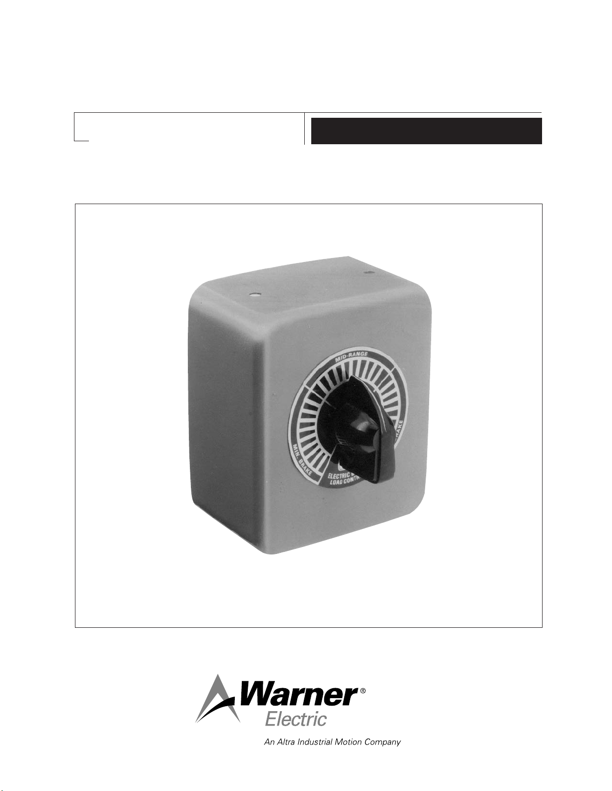
12 Volt Load Control for Electric
Brake Systems No. 1300-78
P-1385
819-0128
Installation Instructions
Page 2
The Warner Electric Load Control provides the
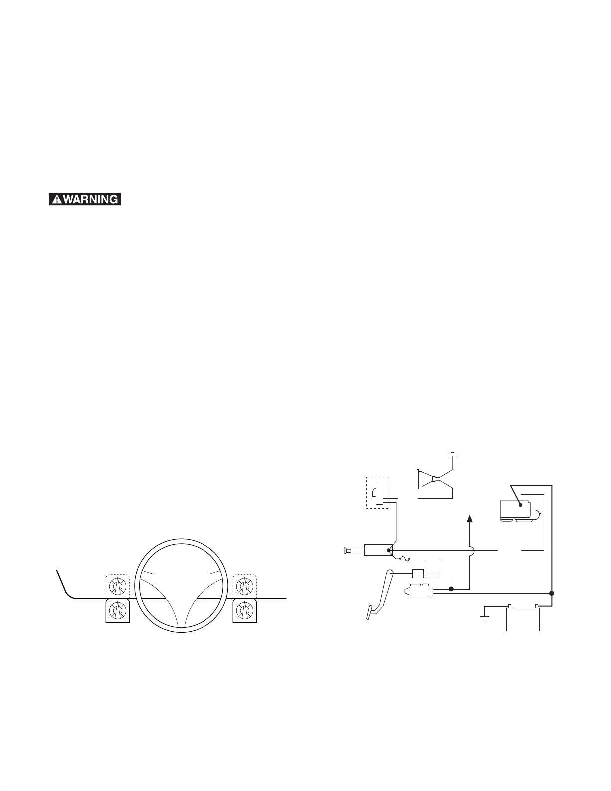
Mount on either side
12v
Battery
Stoplight
switch
Utility controller
mounted on dash
Fuse
Red
Blue
Socket
to Stoplight
Starter
Black
10 Gauge Wire
recommended
Load control
1300-78
(Optional)
Typical Wiring Diagram
Warner Load Control 1300-78
capability to properly proportion the braking
power of the trailer brakes to the trailer weight.
The Load Control is a variable resistor which
allows the operator to reduce current flow to the
trailer brakes by turning the control knob.
Depending on road conditions and trailer load,
the knob can be set at any position between
“MIN BRAKE” and “MAX BRAKE”. The Load
Control provides a broad range of adjustment to
suit a wide variety of operating conditions.
Failure to follow these
instructions may result in product damage,
equipment damage, and serious or fatal
injury to personnel.
Specifications
Resistance Rating: 0-5 ohms
Voltage: 12 volts DC
(use only with 12 volt system)
Brake Coil: Designed for 2-4 brakes wired in
parallel, each with 3.0-3.5 ohms coil resistance.
Installation
Mounting the Control
The Load Control should be mounted under
or behind the towing vehicle’s instrument panel
to the left or right of the steering column,
depending on available space and driver
preference.
For under-dash mounting proceed as follows:
1. While holding the Load Control case in
position, mark the underside of the
instrument panel through the two mounting
holes in the case.
2. Drill two 13/64" diameter holes where
marked, being careful not to damage
anything under the instrument panel.
For behind instrument panel mounting proceed
as follows:
1. Position the face of the Load Control shaft
hole and the washer projection hole.
2. Drill a 13/32" diameter hole for the Load
Control shaft and a 3/16" diameter hole for
the washer projection, where marked. Be
careful not to damage anything under the
instrument panel.
Electrical Connection
The Load Control is to be wired in series with
the electric brake controller and the trailer
brakes. Refer to the “Typical Wiring Diagram”
to connect the Load Control into the brake
system. (See Figure 2)
To mount the Load Control, sit in a normal
driving position and place the Control case so
its knob is within easy reach. (See Figure 1)
2
Warner Electric • 800-825-9050 P-1385 • 819-0128
Figure 1
Figure 2
Page 3

NOTE: Use only 10 or 12 gauge wire meeting SAE
Specification J558a for connecting the Load
Control.
Strip the insulation back about 1/4" from each cut
end. Insert one stripped end into each of the two
insulated ring terminals provided. After inserting
the full length of bared wire, crimp the terminal
using AMP hand tool 59239-4 (G9150-7 for
thinwall insulation) or equivalent. Assemble the
wired terminals to the Load Control, but do not
tighten. One lead is to be attached to the center
terminal, the other to the left hand (heavy
resistance wire side of the resistor) terminal when
facing the rear of the resistor. (See Figure 3)
Figure 3
Under Instrument Panel Installation
Mount the case under the instrument panel,
inserting the tapping screws (with heads inside the
control case) provided through the newly-drilled
holes and tightening securely to the speednuts
included with your Load Control.
Remove the jam nut from the Load Control shaft
and insert the shaft and the washer projection into
the holes provided in the front portion of the case.
Place the Load Control into the case so the
washer projection protrudes through the case
front. Position the dial face on the case and
tighten the jam nut securely with the washer
locating tab projecting through its locator hole.
Assemble the hand knob to the control shaft,
positioning it so the knob screw opposite the
pointer sets against the control shaft flat. Tighten
the setscrews securely. Tighten both electrical
terminal connections, carefully positioning the
lead wires so the ring terminals will not contact
the sides of the case.
Behind Instrument Panel Installation
Remove the jam nut from the Load Control shaft
and insert the shaft and the washer projection
into the holes provided in the front portion of
the case.
Insert the Load Control into its case so the
washer locating tab protrudes through the case
front. Insert the control shaft and locating tab
into the holes provided in the instrument panel.
Position the dial face on the control shaft and
tighten the jam nut securely with the washer
locating tab projecting through the case
instrument panel, and dial face. Assemble the
hand knob to the control shaft, positioning it
so the knob setscrew opposite the pointer sets
against the control shaft flat. Tighten the
setscrew securely. Tighten both electrical
terminal connections, carefully positioning the
lead wires so the ring terminals will not contact
the sides of the case.
Since the Load Control can
become very warm during normal operation,
the case must be used with the control
whether it is mounted under or behind the
instrument panel. When installing the Load
Control, take care to assure that all electrical
wires and other underdash components are
securely fastened to prevent accidental
contact with the resistor winding.
Adjustment
Your Warner Electric Load Control will help
compensate for trailer load variations by limiting
the maximum torque output of the brakes by
adding dropping resistance in the electrical
control line. When towing a trailer loaded to
brake rated capacity, the Load Control must be
set at maximum braking. When pulling an empty
or partially loaded trailer, the Load Control must
be set between maximum and minimum braking
at a position just before the point at which trailer
tire skidding occurs when actuating the hand
control fully on. Failure to use the Warner Electric
Load Control properly can result in excessive
brake torque when stopping a trailer loaded to
less than brake capacity.
Warner Electric • 800-825-9050 P-1385 • 819-0128
3
Page 4

Warranty
Warner Electric LLC warrants that it will repair or replace (whichever it deems advisable) any
product manufactured and sold by it which proves to be defective in material or workmanship within a
period of one (1) year from the date of original purchase for consumer, commercial or industrial use.
This warranty extends only to the original purchaser and is not transferable or assignable without
Warner Electric LLC’s prior consent.
Warranty service can be obtained in the U.S.A. by returning any defective product, transportation
charges prepaid, to the appropriate Warner Electric LLC factory. Additional warranty information may
be obtained by writing the Customer Satisfaction Department, Warner Electric LLC, 449 Gardner
Street, South Beloit, Illinois 61080, or by calling 815-389-3771.
A purchase receipt or other proof of original purchase will be required before warranty service is
rendered. If found defective under the terms of this warranty, repair or replacement will be made,
without charge, together with a refund for transportation costs. If found not to be defective, you will
be notified and, with your consent, the item will be repaired or replaced and returned to you at your
expense.
This warranty covers normal use and does not cover damage or defect which results from
alteration, accident, neglect, or improper installation, operation, or maintenance.
Some states do not allow limitation on how long an implied warranty lasts, so the above limitation
may not apply to you.
Warner Electric LLC’s obligation under this warranty is limited to the repair or replacement of the
defective product and in no event shall Warner Electric LLC be liable for consequential, indirect,
or incidental damages of any kind incurred by reason of the manufacture, sale or use of any defective
product. Warner Electric LLC neither assumes nor authorizes any other person to give any other
warranty or to assume any other obligation or liability on its behalf.
WITH RESPECT TO CONSUMER USE OF THE PRODUCT, ANY IMPLIED WARRANTIES WHICH THE
CONSUMER MAY HAVE ARE LIMITED IN DURATION TO ONE YEAR FROM THE DATE OF ORIGINAL
CONSUMER PURCHASE. WITH RESPECT TO COMMERCIAL AND INDUSTRIAL
USES OF THE PRODUCT, THE FOREGOING WARRANTY IS IN LIEU OF AND EXCLUDES ALL
OTHER WARRANTIES, WHETHER EXPRESSED OR IMPLIED BY OPERATION OF LAW OR
OTHERWISE, INCLUDING, BUT NOT LIMITED TO, ANY IMPLIED WARRANTIES OF
MERCHANTABILITY OR FITNESS.
Some states do not allow the exclusion or limitation of incidental or consequential damages, so the
above limitation or exclusion may not apply to you. This warranty gives you specific legal rights and
you may also have other rights which vary from state to state.
Changes in Dimensions and Specifications
All dimensions and specifications shown in Warner Electric catalogs are subject to change without
notice. Weights do not include weight of boxing for shipment. Certified prints will be furnished without
charge on request to Warner Electric.
Warner Electric LLC
31 Industrial Park Road • New Hartford, CT 06057
815-389-3771 • Fax: 815-389-2582
www.warnerelectric.com
P-1385 • 819-0128 6/12 Printed in USA
 Loading...