

Page 1
12 Volt Utility Controller
for 4, 6, or 8 Brakes No. 1300-76
P-1396
819-0301
Installation Instructions
Page 2
Contents
Introduction . . . . . . . . . . . . . . . . . . . . . . . . . . . . 2
Installation . . . . . . . . . . . . . . . . . . . . . . . . . . . . . 3
Mounting Under Instrument Panel . . . . . . . . . . . 3
Hydraulic Connection . . . . . . . . . . . . . . . . . . . . . 3
Electrical Connection . . . . . . . . . . . . . . . . . . . . . 5
Sensitivity Adjustment . . . . . . . . . . . . . . . . . . . . 6
Optional Equipment . . . . . . . . . . . . . . . . . . . . . . 7
Warranty . . . . . . . . . . . . . . . . . . . . . . . back cover
Introduction
Failure to follow these
instructions may result in product damage,
equipment damage, and serious or fatal injury
to personnel.
The Warner Electric hydraulic/manual Utility
Controller combines manual and automatic
(hydraulic) actuation for the operation of 4, 6,
or 8 twelve volt electric wheel brakes. Some
of the features of this controller are:
• Can be installed to operate automatically
and/or manually.
• Permits manual over-ride of automatic
operation.
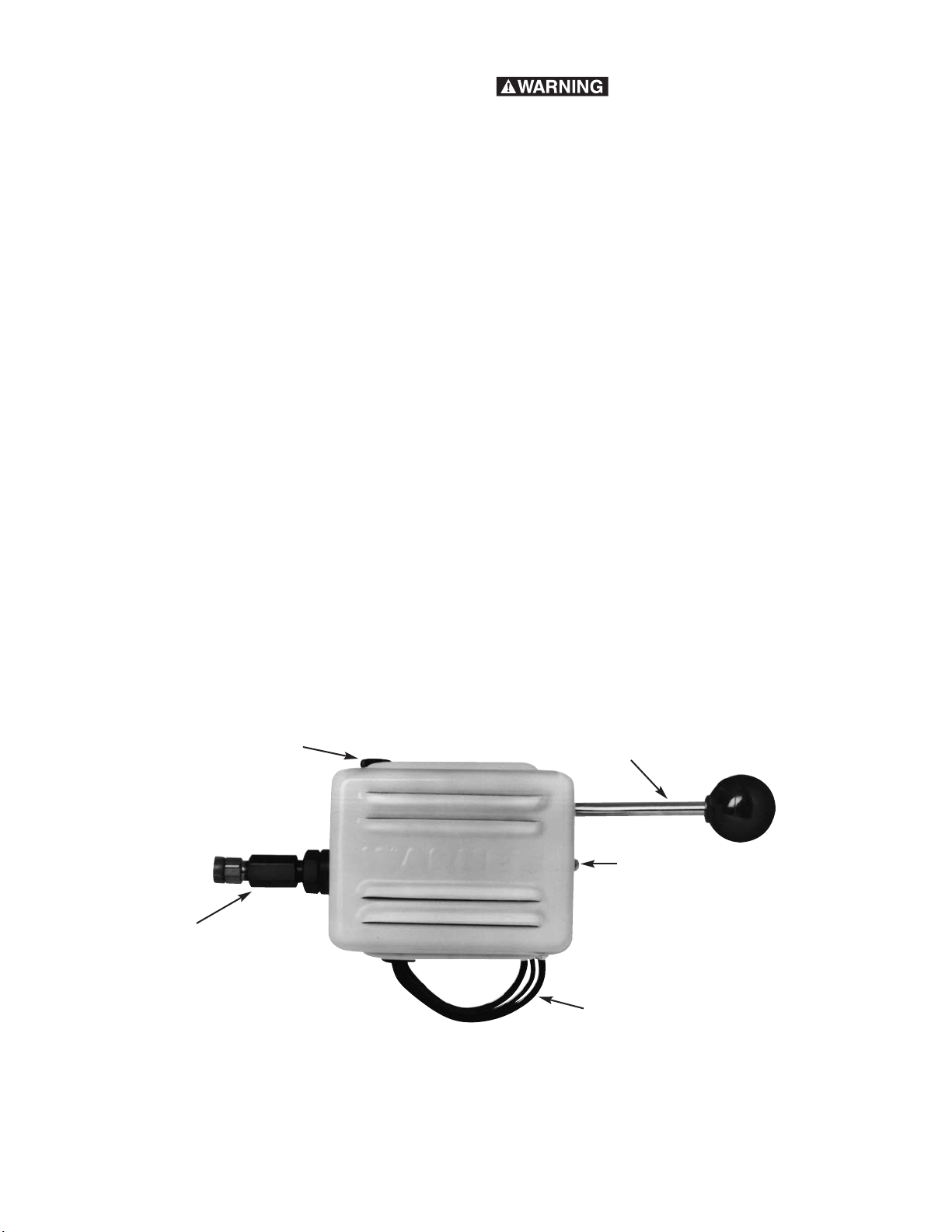
Adjustment Knob
• Brake pedal operated when connected into
towing vehicle hydraulic system.
• Highly sensitive for accurate brake control.
• Wide range of adjustability to compensate for
varying loads and changing road conditions.
• Rated at 30 amperes.
• Low hydraulic fluid displacement – less than
.02 cu. in.
Control Lever
Cover Retaining Screw
Hydraulic Connection
Connection Wires
Warner Electric • 800-825-9050 P-1396 • 819-0301
2
Page 3
Installation
Master Cylinder
Tubing "A" O.D.
Inverted Flare Tube Nut Tee Fittings
For Warner Controllers
Hydraulic Supply
For Rear Brakes
Master Cylinder
Thread Size "B"
3/16 O.D. Tubing Supplied
with Controller
To Controller
F
These instructions provide for ease of
installation. Please follow them carefully.
The basic installation steps are:
1. Mount the controller inside the towing vehicle.
2. Connect the controller into the towing
vehicle’s hydraulic system.
3. Connect the controller electrically.
4. Adjust the controller for synchronized braking.
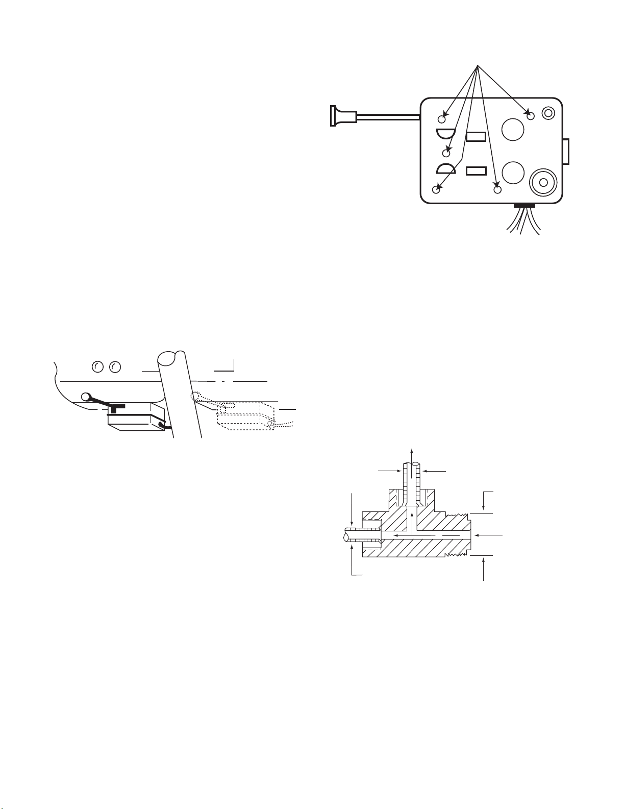
Mounting Holes
Mounting Under Instrument Panel
1. Position the controller under the instrument
panel to the left or right of the steering
column, based on available space and
driver preference.
Mount on Either Side
Figure 1
2. While sitting in a normal driving position,
place the controller so its handle is within
easy reach.
3. Remove the controller cover and, while
holding the controller in place, select at least
two holes through the case which best mount
the controller. Mark the underside of the
instrument panel through these holes.
Figure 2
Hydraulic Connection
1. To provide for automatic actuation of the
controller, a branch tee must be installed in
the hydraulic brake system. Tees are not
furnished with the controller kit because
requirements vary with different makes and
models of towing vehicles. To determine tee
size, measure A and B dimensions from the
towing vehicle’s master cylinder as illustrated
in Figure 3.
4. Drill 3/16" diameter holes where marked,
being careful not to damage anything under
the instrument panel.
5. Attach the controller with 3/16" bolts, nuts
and lock washers, and tighten securely. Bolt
heads are to be inside the controller.
Warner Electric • 800-825-9050 P-1396 • 819-0301
Figure 3
3
Page 4

2. On towing vehicles with dual brake systems
Master
Cylinder
Fire Wall
Controller
Grommet
and Tape
Tee Fitting
(Connection Made on
Output Side of Booster)
Series
Power
Brake
Typical Installation in Series Type Power Brake System
To Front
Brakes
To Rear Brakes
Grommet
or Sealant
Utility
Controller
Fire Wall
Master Cylinder
Adapter
Tee
Typical hydraulic connection arrangement
showing controller, tubing and tee fitting.
(built since 1966) the controller must be
connected to the rear brake portions of
the system.
Note: The rear portion of a master cylinder
does not always control the rear brakes.
Trace the hydraulic tubing to be sure
connections are made in the rear brake
system.
3. Controller Installation in Series Type Power
Brake System. When installing a controller
in a series type power brake system (typically
used in trucks), the connection must be made
on the output side (high pressure side) of the
booster as shown in the figure below.
Determine the correct Tow Craft tee fitting
size by measurement of mating connections.
5. Uncoil the tubing provided. Avoid sharp
bending which could cause kinks. Leave one
or more loops of tubing on the engine side of
the firewall to absorb vibration. To insure that
the tubing remains clean, place a rag over the
exposed end. Feed the tubing through a hole
in the firewall, positioning it to avoid hot
engine members or any surface which
could damage it.
6. Connect the tubing to the branch junction
of the tee and tighten the tubing nut (to
approximately 150 in. lbs.).
Figure 4
4. Disconnect the rear supply line at the master
cylinder (except where adapter fitting is used
or when installation is made in a series type
power brake system – see Figure 5) and
install the tee fitting according to the towing
vehicle manufacturer’s recommendations.
over-tightening at all connections.
Avoid cross-threading and
Figure 5
7. Connect the other end, with male tubing nut,
to the female fitting on the controller cylinder,
but do not hand tighten completely. Take care
not to deform the female thread of the fitting,
which has been pre-tightened during
assembly of the controller.
8. To bleed the hydraulic system, wrap a rag
around this connection and depress the brake
pedal slowly and often enough to fill the
tubing with fluid. All air must be bled from
this line. When hydraulic fluid appears on
the rag, remove it and tighten the tubing nut
securely to stop all leakage (correct torque
approximately 150 in. lbs.), while the pedal is
depressed. The factory installed controller
fitting should not be retightened.
When the tubing nut is
tightened, use a wrench to hold female
fitting. Rocking the female fitting will
cause leakage at the threads.
Warner Electric • 800-825-9050 P-1396 • 819-0301
4
Page 5

Figure 6
9. To test for sponginess and leaks, pump the
brake pedal and hold it depressed for
approximately one minute. If sponginess
exists, the entire system should be bled at
the wheel cylinders. Refill the master cylinder
fluid reservoir as required.
Electrical Connection
1. Electrical connection is required for all
installations. Approximately 25 ft. of
automotive-type multistranded 12 gauge or
heavier single wire with tough, thermoplastic
insulation meeting SAE standard J558a is
required.
4. Remove a knock-out plug or cut a hole in the
firewall near the mounted controller.
5. Cut the wire to a proper length for reaching
the controller. Strip the wire and feed it
through the firewall hole.
6. Connect this wire to the blue brake lead wire
extending from the back of the controller.
Note: Solder or crimp clamp connections
will be required when connecting all three
controller lead wires. Wrap electrician’s
tape around all bare wire joints. Do NOT
use twist-type connectors.
7. Making a chassis ground connection is the
next installation step. Strip one end of the
remaining length of hook-up wire and connect
it securely to the ground terminal of the
socket at the rear of the towing vehicle.
8. Feed the wire under the towing vehicle to a
convenient chassis ground, such as a body
or chassis nut and bolt, battery ground-post,
etc. Cut and strip the wire and attach it
securely to this ground. A good ground
connection is essential for proper
operation.
Note: When towing a trailer which will carry
variable loads, or which is light weight when
compared with its brake capacity, a Warner
Electric Load Control part No. 1300-78, may
be required to properly proportion braking
force between the trailer and the towing
vehicle. See Optional Equipment.
9. Two Utility Controllers leads are still to be
connected. The red lead actuates the
stoplights when the controller is operated
manually. An interrupted stoplight circuit for
turn signals is used on most towing vehicles.
Connect the controller’s red lead to the output
side of the towing vehicle stoplight switch.
(This switch could be a pressure switch
2. An electrical socket which mates with the
trailer power cable is to be installed in the
rear of the towing vehicle. Strip one end of
the hook-up wire and connect it to the brake
terminal of this socket.
3. Secure a single length of wire from the brake
connection of the socket to the underside of
the towing vehicle and lead it to the engine
firewall. Position the wire to insure maximum
protection from scraping on the road surface
located in the brake line or a limit switch
activated by the brake pedal.) Connect an
inline fuse in series between the red lead and
the stoplight switch. This fuse should be the
same type and rating as recommended for
the tow vehicle’s existing stoplight circuit.
Splice a short length of hook-up wire to the
red lead to reach the stoplight switch output.
If your towing vehicle has some other system,
consult your automotive dealer.
in rough terrain, flying stones, spray, etc. Also
avoid attaching wires near mufflers and
exhaust pipes. Wires should be clamped at
frequent intervals.
Warner Electric • 800-825-9050 P-1396 • 819-0301
5
Page 6

BLUE
SOCKET
TO STOPLIGHT
10 GAU GE W IR E
RECOMMENDED
LOAD CONTROL
1300-78
OPTIONAL
UTILITY CONTROLLER
MOUNTED ON DASH
MECHANICAL
STOPLIGHT
SIGNAL
STOPLIGHT
SWITCH
RED
FUSE
BATT ERY
BLACK
10 GAU GE W IR E
RECOMMENDED
STAR TE R
Figure 7
10. The black or power lead of the controller is
last to be connected. Enough hook-up wire
should remain to make this connection.
Strip one end of this hook-up wire and feed
it through a hole in the firewall from the
engine side. Solder or crimp clamp this
wire to the black controller lead.
11. Detach one of the power cables from the
towing vehicle battery to prevent arcing.
12. Cut the hook-up wire to the proper length
to attach it to the live terminal of the starter
solenoid or relay, strip the wire and
complete the connection. Attaching this
lead completes your electrical connection.
Re-connect the towing vehicle battery
cable.
13. Tape together wires leading from the
controller and secure them to the steering
column or underside of the dash. Plug all
holes in the fire wall with sealant or rubber
grommets to prevent exhaust gases from
6
entering through the holes and to protect
the wires from abrasion.
Warner Electric • 800-825-9050 P-1396 • 819-0301
Sensitivity Adjustment
After the entire controller system is installed and
operating, the controller sensitivity must be
adjusted to synchronize the towing vehicle and
trailer braking systems. Proper adjustment of
your controller/braking system is important
for safe automatic operation.
Warner Electric’s Utility Controller has an
adjustment knob to control trailer brake
sensitivity. This adjustment does not affect
maximum braking capacity of the trailer brakes.
Because of the wide variety of towing vehicles
encountered, balancing towing vehicle brakes
and trailer brakes is necessary for smooth,
synchronized stops. To achieve this, the
controller adjustment should be hand set to
provide a slight lead in trailer braking over towing vehicle braking. Setting the adjustment in the
“MORE” brake direction will increase the trailer
brake rate of application, while setting in the
“LESS” direction will decrease the trailer brake
rate of application. When proper adjustment has
been achieved, there should be no sensation of
the trailer pushing or pulling the towing vehicle
during a stop. When this setting has been
reached, no further adjustment should be
required. For operating with varying load
weights, read the following section on “Optional
Equipment.”
Page 7

Optional Equipment
When the trailer load is variable or less than
trailer brake capacity, a Warner Electric Load
Control, part no. 1300-78 should be added in
series with the brake circuit. The Load Control
provides the capability to properly proportion the
braking power of the trailer brakes to the trailer
weight. The Load Control is connected into the
trailer brake wire connected to the blue lead
from the controller. Its position is shown in the
wiring diagram under “Electrical Connection.”
The illustration shows the simplicity of adjusting
this resistor to increase or decrease trailer brake
torque. Contact your Warner Electric distributor
or the factory if you require additional
information.
Warner Electric • 800-825-9050 P-1396 • 819-0301
7
Page 8

Warranty
Warner Electric LLC warrants that it will repair or replace (whichever it deems advisable) any
product manufactured and sold by it which proves to be defective in material or workmanship within a
period of one (1) year from the date of original purchase for consumer, commercial or industrial use.
This warranty extends only to the original purchaser and is not transferable or assignable without Warner
Electric LLC’s prior consent.
Warranty service can be obtained in the U.S.A. by returning any defective product, transportation charges
prepaid, to the appropriate Warner Electric LLC factory. Additional warranty information may be obtained by
writing the Customer Satisfaction Department, Warner Electric LLC, 449 Gardner Street, South Beloit,
Illinois 61080, or by calling 815-389-3771.
A purchase receipt or other proof of original purchase will be required before warranty service is
rendered. If found defective under the terms of this warranty, repair or replacement will be made, without
charge, together with a refund for transportation costs. If found not to be defective, you will be notified and,
with your consent, the item will be repaired or replaced and returned to you at your expense.
This warranty covers normal use and does not cover damage or defect which results from
alteration, accident, neglect, or improper installation, operation, or maintenance.
Some states do not allow limitation on how long an implied warranty lasts, so the above limitation may not
apply to you.
Warner Electric LLC’s obligation under this warranty is limited to the repair or replacement of the
defective product and in no event shall Warner Electric LLC be liable for consequential, indirect,
or incidental damages of any kind incurred by reason of the manufacture, sale or use of any defective
product. Warner Electric LLC neither assumes nor authorizes any other person to give any other warranty
or to assume any other obligation or liability on its behalf.
WITH RESPECT TO CONSUMER USE OF THE PRODUCT, ANY IMPLIED WARRANTIES WHICH THE
CONSUMER MAY HAVE ARE LIMITED IN DURATION TO ONE YEAR FROM THE DATE OF ORIGINAL
CONSUMER PURCHASE. WITH RESPECT TO COMMERCIAL AND INDUSTRIAL
USES OF THE PRODUCT, THE FOREGOING WARRANTY IS IN LIEU OF AND EXCLUDES ALL OTHER
WARRANTIES, WHETHER EXPRESSED OR IMPLIED BY OPERATION OF LAW OR
OTHERWISE, INCLUDING, BUT NOT LIMITED TO, ANY IMPLIED WARRANTIES OF
MERCHANTABILITY OR FITNESS.
Some states do not allow the exclusion or limitation of incidental or consequential damages, so the above
limitation or exclusion may not apply to you. This warranty gives you specific legal rights and you may also
have other rights which vary from state to state.
Changes in Dimensions and Specifications
All dimensions and specifications shown in Warner Electric catalogs are subject to change without notice.
Weights do not include weight of boxing for shipment. Certified prints will be furnished without charge on
request to Warner Electric.
Warner Electric LLC
31 Industrial Park Road • New Hartford, CT 06057
815-389-3771 • Fax: 815-389-2582
www.warnerelectric.com
P-0301 • 819-1396 6/12 Printed in USA
 Loading...