

Page 1
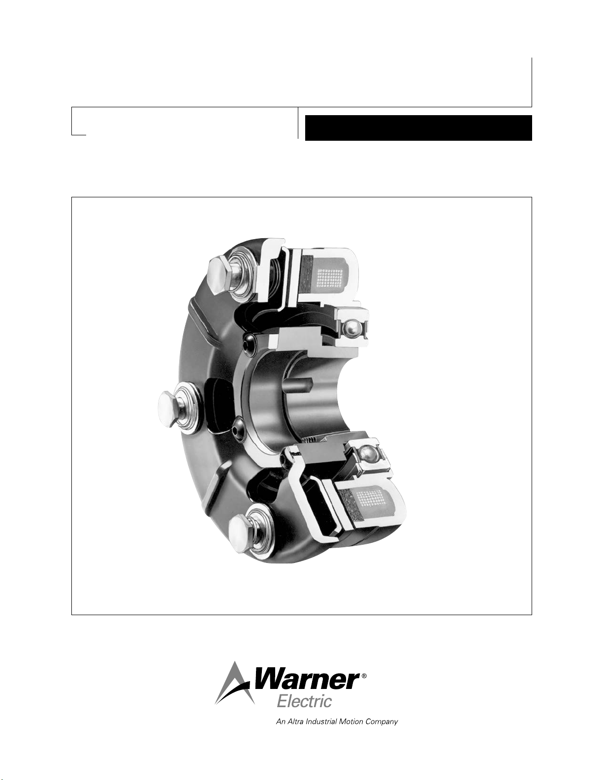
Electro-Brake 375, 475, 650, 825,
1000, 1225
P-211
819-0043
Installation Instructions
Page 2
Contents
Installation Instructions . . . . . . . . . . . . . . . . . . .2
Electrical Coil Data . . . . . . . . . . . . . . . . . . . . . .5
Burnishing and Maintenance . . . . . . . . . . . . . .6
Illustration Drawings
EB-375 EB-475 EB-650 . . . . . . . . . . . . . . . .8
EB-825 . . . . . . . . . . . . . . . . . . . . . . . . . . . . .12
EB-1000 EB-1225 . . . . . . . . . . . . . . . . . . . .14
Bushing Part Number . . . . . . . . . . . . . . . . . . .17
Warranty . . . . . . . . . . . . . . . . . . . . . .Back Page
Failure to follow these
instructions may result in product damage,
equipment damage, and serious or fatal
injury to personnel.
Follow the installation instructions in this
manual carefully to ensure safe, reliable
operation. All stated or implied manufacturer
warranties are voided if this product is not
installed in accordance with these
instructions.
Electro-Brakes
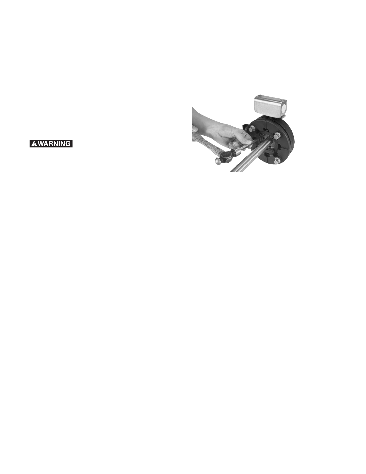
5. Secure the assembly in position by
alternately tightening the two setscrews. Tap
the bushing lightly from time to time during
the tightening process to make certain that it
seats in properly. (Figure 1)
Figure 1
6. Install the torque arm. (See Section C)
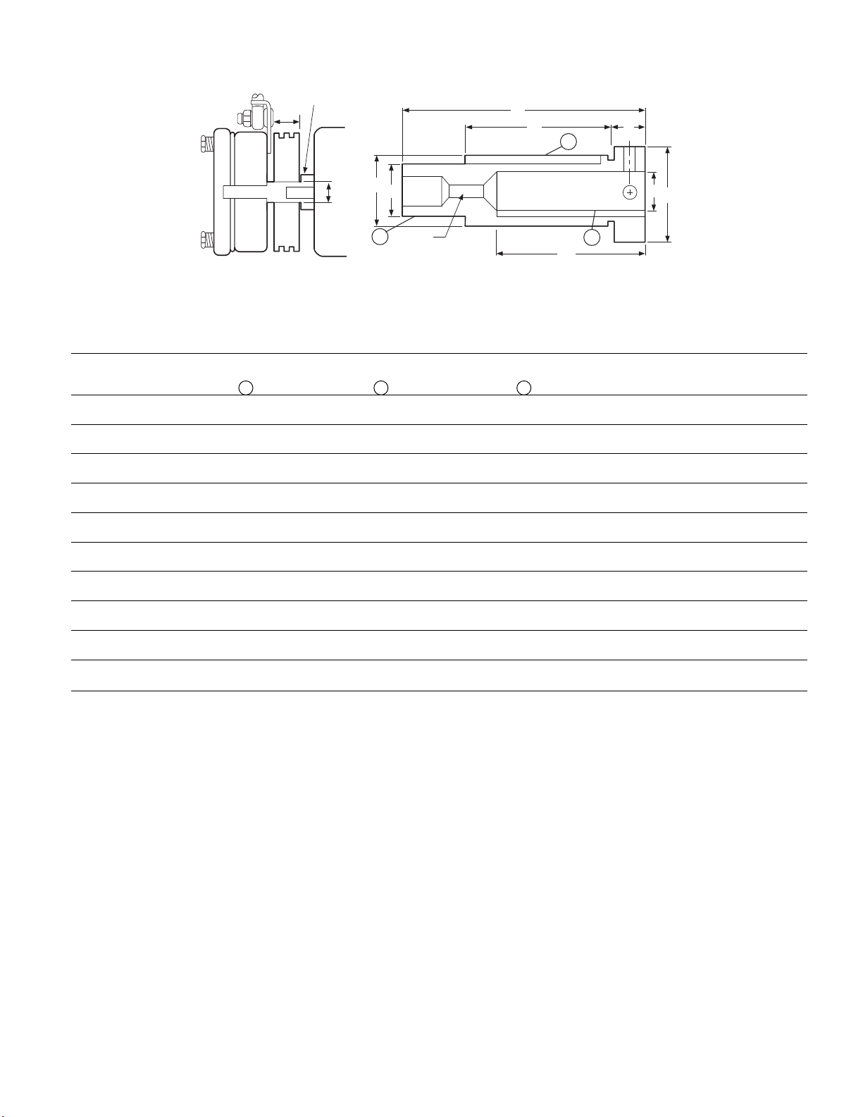
B. Motor Mounting
An optional shaft extension is available for
mounting all Electro-Brakes, except EB-825, on
a single shaft extension motor. (Figure 2)
Electro-Brakes may be mounted on either a
thru-shaft or a single shaft extension motor.
Follow the appropriate instructions for each
application.
A. Thru-Shaft Mounting
1. EB-375. This unit has a straight bore and
mounts directly on a thru-shaft. Slide the unit
on the shaft and secure in place by
alternately tightening the two set screws in
the hub.
Mount all other EB units to a thru-shaft with
a tapered bushing as follows:
2. Insert a key in the shaft keyway.
3. Place a tapered bushing in the Electro-Brake.
4. Insert the set screws loosely into the bushing,
and slide the brake assembly onto the shaft.
1. Mount a standard sheave, pulley, or sprocket
on section E of the shaft extension with either
a tapered bushing or a straight bore.
2. Insert the proper tapered bushing into the
Electro-Brake (except EB-375).
3. Assemble the set screws loosely in the
bushing.
4. Mount the Electro-Brake on the end of the
shaft extension.
5. Mount the complete assembly on the motor
shaft and tighten the set screws.
6. Install the belts or chain on the sprocket,
pulley, or sheave.
7. Install the torque arm. (See Section C)
Warner Electric • 800-825-9050 P-211 • 819-0043
2
Page 3
Motor
Adapter
A
B
D
E
B
C
G
A
I
F
H
(Threaded
Rem
oval Hole)
2
3
1
All dimensions are nominal unless otherwise noted.
Model A Kwy. Part No. 1 B Kwy. Part No. 2 C Kwy. Part No. 3 Size DEFGH I
EB-375 5/8 3/16x * 7/8 3/16x 590-0016 5/8 3/16x 590-0043 None 4.391 2 .391 2 1/4-20 1.125
EB-375 7/8 3/16x * 1-1/4 1/4x 590-0022 5/8 3/16x 590-0043 None 4.578 2-1/4 .516 2-1/4 1.500
EB-475 1-1/8 1/4x * 1-5/8 3/8x 590-0041 1 1/4x ** #1008 4.516 2-3/4 .641 2-3/4 1/2-13 1.750
EB-650 1-3/8 5/16x *21/2x 590-0042 1-3/8 5/16x 590-0044 #1310 5.547 3-3/8 .641 3-3/8 1/2-13 2.125
EB-650 1-5/8 3/8x * 2-1/4 1/2x 590-0042 1-3/8 5/16x 590-0044 #1310 6.172 4 .641 4 2.375
EB-1000 1-5/8 3/8x * 2-15/16 3/4x 590-0052 1-5/8 3/8x ** #1615 8.297 5-1/4 5 3/4-10 2.937
EB-1000 1-7/8 1/2x * 2-15/16 3/4x 590-0052 1-5/8 3/8x ** #1615 2.937
EB-1000 2-1/8 1/2x 590-0062 2-15/16 3/4x 590-0069 1-5/8 3/8x ** #1615 2.937
EB-1225 2-1/8 1/2x * 3-3/4 7/8x 590-0049 2-1/8 1/2x 590-0048 #2517 10.672 7-1/4 6-7/8 7/8-9 3.750
EB-1225 2-3/8 5/8x * 3-3/4 7/8x 590-0049 2-1/8 1/2x 590-0048 #2517 3.750
*Standard Square Key Furnished with Motor. **Special Key Furnished with Bushing.
3/32 3/32 3/32 4.359 .359 UNC
3/32 1/8 3/32 4.742 .484
1/8 3/16 1/8 1" 4.484 .609 UNC
5/32 1/4 5/32 1-3/8" 5.515 .609 UNC
3/16 1/4 5/32 1-3/8" 6.140 .609
3/16 7/16 7/32 1-5/8" 8.265 UNC
7/32 7/16 7/32 1-5/8"
1/8 5/16 7/32 1-5/8"
7/32 7/16 9/32 2-1/8" 10.640 UNC
9/32 7/16 9/32 2-1/8"
Figure 2
Dodge
Key Key Key Bushing
C. Installing the Torque Arm
The Electro-Brake magnet is bearing-mounted
on the hub and is provided with a torque tab to
prevent the magnet from rotating. When the
brake is de-energized, the tab need only resist
the bearing drag; however when the brake is
energized the full braking torque is applied to
the tab and restraining mechanism. Since the
brake torque is usually substantial, the
customary restraining method is to use a rod
with a ball joint, as furnished with the
Warner Electric • 800-825-9050 P-211 • 819-0043
Electro-Brake. This torque arm should be
sufficiently long for any normal application and
should be mounted so the rod is in tension
rather than compression when brake torque is
applied. Consult the factory for a
recommendation if a longer arm is needed.
The threaded shaft can be cut to any desired
length.
3
Page 4
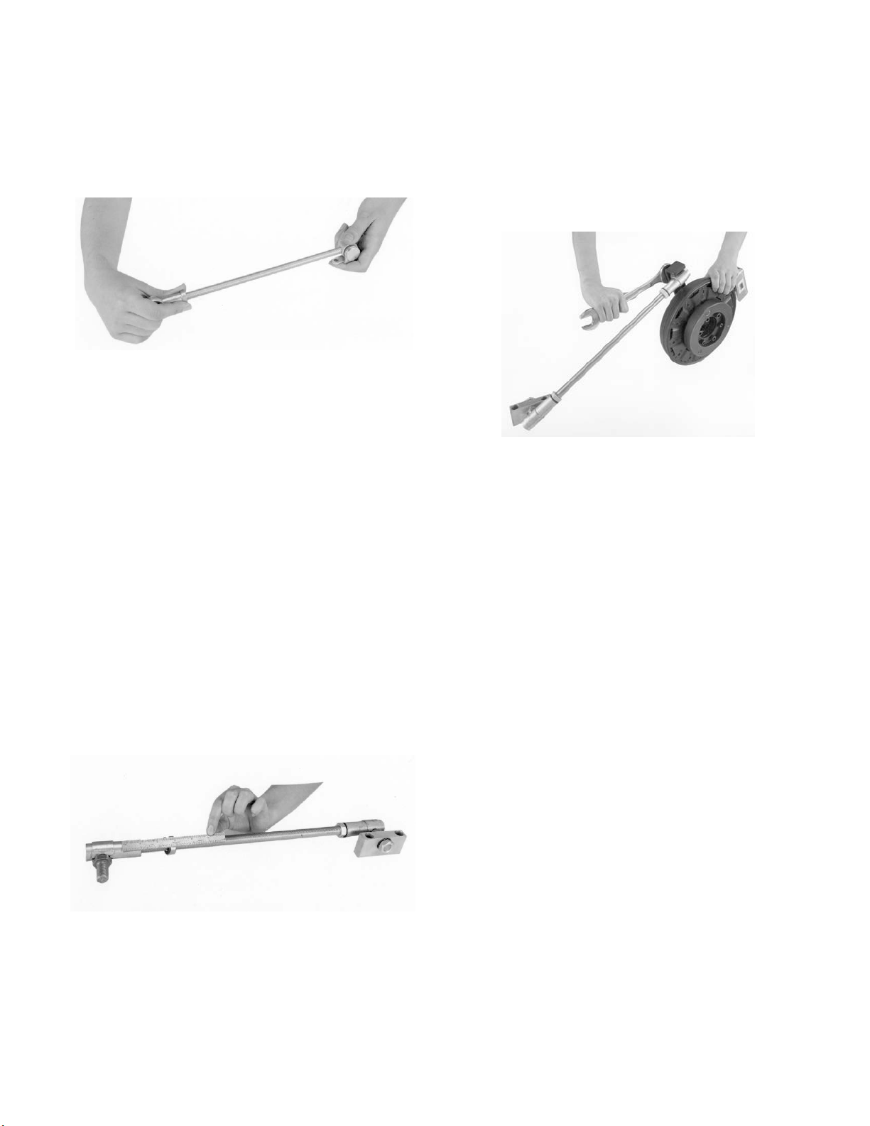
EB-375, 475, 650, 825
1. Secure the rod end bearing to the torque arm
shaft. (Figure 3)
Figure 3
2. Secure the rod end of the torque arm
assembly to the tab on the Electro-Brake.
5. Secure the torque arm to the brake so that
the ball joint is inside the tab and the jam nut
is on the outside (Figure 5). Rotate the ball
joint to facilitate this operation. Simply loosen
the jam nut on the shaft, and reposition the
jam nut to the desired position. Retighten the
jam nut to 90-95 ft. lbs. torque.
Figure 5
3. Secure the other end of the torque arm to a
base. Refer to Figure 6 to determine the
correct position for securing the tab and
torque arm. Although the arm may be
mounted in either direction, installing it as
illustrated is important to good bearing life.
EB-1000, 1225
4. Assemble the ball joints to both ends of the
threaded shaft. At least one inch of the shaft
must be threaded into each ball joint.
(Figure 4)
6. Secure the other end of the torque arm to a
base. Refer to Figure 6 to determine the
correct position for securing the tab and
torque arm. Although the arm may be
mounted in either direction, the bracket must
be parallel to the torque rod.
D. Electrical Installation
A wiring diagram showing the electrical
connections that must be made is furnished
with each Warner Electric control. Service
Manual P-239 includes complete information on
all standard power supplies.
E. Wearing Parts
The magnet and armature, the two main wearing
parts, wear at nearly the same rate. When these
parts are worn out, Warner Electric recommends
that the entire brake be replaced.
Figure 4
Warner Electric • 800-825-9050 P-211 • 819-0043
4
Page 5
Electrical Coil Data
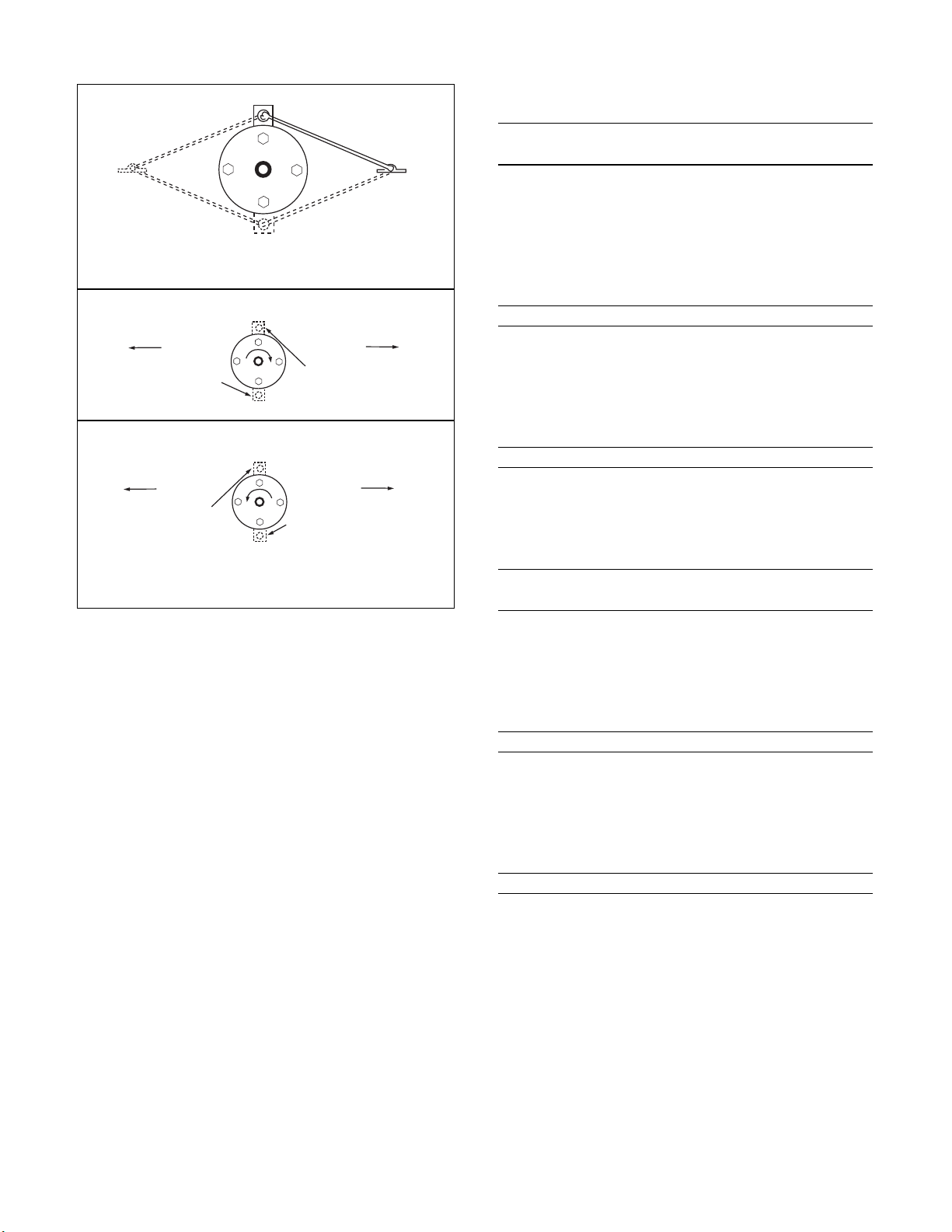
ROTATI ON
ROTATI ON
TORQ UE ARM M AY BE MOUNTED
IN A NY D IRE CTION
CLOCKWISE ROTATI O N
COUNTER-CLOCKWISE ROTATION
IF DIRECTION OF
BELT PULL
THEN LOCATE
TORQ UE ARM TA B
IF DIRECTION OF
BELT PULL
THEN LOCATE
TORQ UE ARM TA B
IF DIRECTION OF
BELT PULL
THEN LOCATE
TORQ UE ARM TA B
IF DIRECTION OF
BELT PULL
THEN LOCATE
TORQ UE ARM TAB
ELECTRO-BRAKE
VIEWED FROM ARMATURE SIDE
EC/EB-375 EC EC EB EB
Voltage — DC 90 6 90 6
Resistance @ 20°C — Ohms 453.5 2.10 446.8 1.96
Current — Amperes .198 2.85 .201 3.07
Watts 17 17 18 18
Coil Build-up — Milliseconds 62 59 50 52
Coil Decay — Milliseconds 13 15 8 10
EC/EB-475 EC EC EB EB
Voltage — DC 90 6 90 6
Resistance @ 20°C — Ohms 368.9 2.32 443.1 2.05
Current — Amperes .244 2.58 .203 2.93
Watts 22 16 18 18
Coil Build-up — Milliseconds 92 90 80 70
Coil Decay — Milliseconds 18 16 89
EC/EB-650 EC EC EB EB
Voltage — DC 90 6 90 6
Resistance @ 20°C — Ohms 225 1.16 257.2 1.24
Current — Amperes .4 5.19 .35 4.84
Watts 36 31 32 29
Coil Build-up — Milliseconds 120 110 112 105
EC/EB-825 EC EC EB EB
Figure 6
Voltage — DC 90 6 90 6
Resistance @ 20°C — Ohms 221 1.098 223.3 1.27
Current — Amperes 407 5.464 .4 4.74
Watts 37 33 36 28
Coil Build-up — Milliseconds 225 180 170 170
Coil Decay — Milliseconds 130 115 80 70
EC/EB-1000 EC EC EB EB
Voltage — DC 90 6 90 6
Resistance @ 20°C — Ohms 248.7 1.23 248.7 1.23
Current — Amperes .36 4.87 .36 4.87
Watts 33 29 33 29
Coil Build-up — Milliseconds 250 220 235 205
Coil Decay — Milliseconds 70 80 70 80
EC/EB-1225 EC EC EB EB
Voltage — DC 90 6 90 6
Resistance @ 20°C — Ohms 207.3 1.04 261.7 1.33
Current — Amperes .43 5.79 .34 4.5
Watts 39 35 31 27
Coil Build-up — Milliseconds 500 480 460 435
Coil Decay — Milliseconds 220 240 190 140
Warner Electric • 800-825-9050 P-211 • 819-0043
5
Page 6

Burnishing and Maintenance
Burnishing
Intimate metal to metal contact is essential
between the armature and the metal rings
(poles) of the magnet or rotor. Warner Electric
clutches and brakes leave the factory with the
friction material slightly undercut to assure good
initial contact.
Normally, the desired wearing-in process occurs
naturally as the surfaces slip upon engagement.
The time for wear-in, which is necessary to
obtain the ultimate torque of the unit, will vary
depending on speed, load, or cycle duty.
If maximum torque is required immediately after
installation, the unit should be burnished by
slipping the friction surfaces together at reduced
voltage. It is recommended that the burnishings
be done right on the application, if at all
possible.
Burnishing at high speed will result in a
smoother wear-in pattern and reduce the time
for burnishing. The voltage should be set at
approximately 30% or 40% of the rated value.
The unit should be cycled on and off to allow
sufficient time between slip cycles to prevent
overheating.
When a Warner Electric brake or clutch is
properly assembled and installed, no further
servicing, lubrication, or maintenance should be
required throughout the life of the unit.
Maintenance
Re-machining the face of a worn armature is not
recommended. If a replacement armature is to
be used with a used magnet, it is necessary to
re-machine the worn magnet face. In refacing a
magnet: (1) machine only enough material to
clean up the complete face of the magnet;
(2) hold the face within .005" of parallel with the
mounting plate; and (3) undercut the molded
facing material .001" - .003" below the metal
poles.
Heat: Excessive heat and high operating
temperatures are causes of rapid wear. Units,
therefore, should be ventilated as efficiently as
possible, especially if the application requires
fast, repetitive cycle operation.
Foreign Materials: If units are used on
machinery where fine, abrasive dust, chips or
grit are dispelled into the atmosphere, shielding
of the brake may be necessary if maximum life
is to be obtained.
Where units are used near gear boxes or
transmissions requiring frequent lubrication,
means should be provided to protect the friction
surfaces from oil and grease to prevent serious
loss of torque.
Oil and grease accidentally reaching the friction
surfaces may be removed by wiping with a rag
dampened with a suitable cleaner, which leaves
no residue. In performing this operation, do not
drench the friction material.
If the friction materials have been saturated with
oil or grease, no amount of cleaning will be
completely effective. Once such a unit has been
placed back in service, heat will cause the oil to
boil to the surface, resulting in further torque
loss.
Wear Pattern: Wear grooves appear on the
armature and magnet surfaces. This is a normal
wear condition, and does not impair functioning
Torque Loss: If a brake or clutch slips or loses
torque completely, the initial check should be
the input voltage to the magnet as follows:
of the unit. Normally, the magnet and armature,
as a mating pair, will wear at the same rate. It is
the usual recommendation that both
components be replaced at the same time.
Warner Electric • 800-825-9050 P-211 • 819-0043
6
90-Volt Series: Connect a DC voltmeter with a
range of 0-100 or more directly across the
magnet terminals. With the power on and the
Page 7

potentiometer turned up, a normal reading is 90
volts, although 85 to 95 is satisfactory. The
reading should drop as the potentiometer
control is adjusted counterclockwise.
24-Volt Series: Use a DC voltmeter with a range
of 0-30 volts or more. A normal reading is
approximately 22-26 volts.
6-Volt Series: Use a DC voltmeter of
approximately 0-15 volt range. A normal reading
is from 5.5 to 6.5 volts.
The above checks normally are sufficient.
Further checks may be made as follows: a low
range ammeter, when connected in series with
one magnet lead, will normally indicate
approximately .40 amperes for the 90 volt units,
1.0 ampere for the 24 volt, and 3.5 amperes for
the 6 volt series. These readings are with the
power on and the potentiometer control in the
maximum position.
Ohmmeter checks should be made with the
power off and the circuit open (to be certain,
disconnect one lead to the magnet). Average
resistance for the 90 volt series is 220 ohms; for
the 24 volt, 20 ohms; and for the 6 volt series,
1.5 ohms. A very high or infinite resistance
reading would indicate an open coil.
If the above checks indicate that the proper
voltage and current is being supplied to the
magnet, mechanical parts should be checked to
assure that they are in good operating condition
and properly installed.
Warner Electric • 800-825-9050 P-211 • 819-0043
7
Page 8

N
M
L
I
H
F
G
D
C
B
A
R
O
P
Q
AA
BB
DD
EE
Z
CC
Y
VU
X
W
S
T
EB-375, EB-475, EB-650
Adapter Requirements
For thru-shaft mounting, specify bore size. For
EB-475 and EB-650 order bushing separately.
EB-375 does not require a bushing.
For motor mounting, order adapter separate
(see page 4).
Bore Sizes and Keyway
Size Bore Dia. Keyway
375 .626/.625 3/16 x 3/32
.501/.500 1/8 x 1/16
475 .500/.563 1/8 x 1/16
.625/.875 3/16 x 3/32
.938/1.000 *1/4 x 1/8
650 .500/.563 1/8 x 1/16
.625/.875 3/16 x 3/32
1.250/1.313 1/4 x 1/8
1.313/1.375 5/16 x 5/32
*Key Furnished
Warner Electric • 800-825-9050 P-211 • 819-0043
8
Page 9

EB-375, EB-475, EB-650
All dimensions are nominal, unless otherwise noted.
Size A Max. B Dia. C Min. D Dia. EFGH Dia. IJKLMN Max. O
375 4.078 3.125 .7505 – .031 1.656 – 1.375 3.344 10-32 UNF .188 1.047 1.547 2.438 .844
475 5.172 4.000 1.663 1.594 – 1.000 1.000 1.781 3.875 ––3.031 1.547 2.922 1.094
650 6.578 5.125 2.343 2.281 – 1.313 1.000 2.563 4.656 ––3.031 1.547 3.109 1.031
Size PQRS Max. TUV W XYZAA BB CC DD EE
375 .281 .625 .094 4.453 3.750 2.453 .656 1.000 8.000 .781 .359 1.500 2.000 .270 .250 .781
Min. .260
475 .313 .531 .125 4.984 3.750 3.094 .781 1.000 10.000 .688 .391 1.500 2.000 .270 .250 .781
Max. .260
650 .344 .641 .203 5.766 3.750 4.063 .781 1.125 11.000 .844 .438 1.500 2.000 .270 .250 .781
Max. .260
-3A x 1/4
Specifications
Inertia–WR2(lb. ft2)
Model Size Voltage DC Static Torque (lb. ft.) Max. Speed RPM Arm. & Carrier Hub Total Weight lbs.
EB-375 6, 24, 90 16 5000 .010 .001 4
EB-475 6, 24, 90 30 4500 .072 .006 7
EB-650 6, 24, 90 95 3600 .106 .010 11.3
Warner Electric • 800-825-9050 P-211 • 819-0043
9
Page 10

EB-375, EB-475, EB-650
1-1
1-2
1-4
1-3
1
9
11
10
4
3
1-5
2
3
5
6
7
14
Optional
12
8
15
13
Warner Electric • 800-825-9050 P-211 • 819-0043
10
Page 11

EB-375, EB-475, EB-650
Component Parts
EB-375 EB-475 EB-650
Item Description Part No. Qty. Part No. Qty. Part No. Qty.
1 Armature & Carrier Assembly 5380-101-006 1 5381-101-004 1 5382-101-005 1
1-1 Capscrew 797-1214 3 797-1214 4 797-0086 4
1-2 Lockwasher 950-0102 3 950-0102 4 950-0103 4
1-3 Autogap Accessory 5180-101-011 3 5181-101-010 4 5181-101-010 4
1-4 Carrier 5380-295-002 1 5381-295-003 1 5382-295-002 1
1-5 Armature 5180-111-002 1 5181-111-002 1 5281-111-002 1
2 *Bushing 180-0410-180-0418 180-0421-180-0435
3 Hub 1 540-0524 1 540-0523 1
1/2" Bore 540-0520
5/8" Bore 540-0519
4 Set Screw 2
1/2" Bore 797-0368
5/8" Bore 797-0366
5 Retainer Ring 748-0101 1 748-0102 1 748-0104 1
6 Ball Bearing 166-0150 1 166-0110 1 166-0104 1
7 Retainer Ring 748-0018 1 748-0002 1 748-0004 1
8 Magnet 111
6 volt 5380-631-003 5381-631-003 5382-631-003
24 volt 5380-631-004 5381-631-004 5382-631-005
90 volt 5380-631-002 5381-631-002 5382-631-002
9 Locknut 661-0050 1 661-0051 1 661-0004 1
10 Washer 950-0029 1 950-0026 1 950-0030 1
11 Rod End Bearing 166-0186 1 166-0187 1 166-0188 1
12 Torque Arm Rod Assembly 5380-112-001 1 5381-112-001 1 5382-112-001 1
13 Terminal Accessory 5311-101-001 1 5311-101-001 1 5311-101-001 1
14 Adapter (optional) 111
5/8" Motor Shaft 5380-101-005
7/8" Motor Shaft 5380-101-004
1-1/8" Motor Shaft 5381-101-003
1-3/8" Motor Shaft 5382-101-003
1-5/8" Motor Shaft 5382-101-002
15 Conduit Box 5200-101-010 1 5200-101-010 1 5200-101-010 1
*See page 20 for specific part numbers.
These units when used with the correct Warner Electric conduit box, meets the standards of UL508 and are listed under guide care #NMTR,
file #59164. These units are CSA Certified under file #LR11543.
1/2” to 1” bore 1 1/2” to 1-3/8” bore 1
Warner Electric • 800-825-9050 P-211 • 819-0043
11
Page 12

EB-825
Removable
Plug In Ends
for 1/2" Conduit
Q
P
R
T
S
J
I
H
G
ABC
M
O
N
ED
Z
W
V
Y
R
12
Size A Max. B Max. C Dia. DEFGHIJ Max. KLM
825 8.656 4.625 2.625 .563 1.250 – 5.641 1.344 1.547 3.375 ––.344
Size NOP Max. QRS TUVWXYZ
825 1.031 .641 6.813 3.750 4.813 11.000 1.125 – 1.500 2.000 – .270 .781
Specifications
Model Size Voltage DC Static Torque lb. ft. Max. Speed RPM Arm. & Hub Total Weight lbs.
EB-825 6, 24, 90 125 3600 .459 20
Warner Electric • 800-825-9050 P-211 • 819-0043
Inertia–WR2(lb. ft2)
.260
Page 13

EB-825
Component Parts
EB-825
Item Description Part No. Qty.
1 Armature Assembly 5383-111-001 1
1a Hub 540-1299 1
1b Autogap Assembly 5201-101-008 3
1c Armature 5282-111-001 1
2 *Bushing 180-0002 to 180-0018
1/2" to 1-1/2" Bore 1
3 Ball Bearing 166-0168 1
4 Retainer Ring 748-0120 1
5 Retainer Ring 748-0584 1
6 Adapter Ring 748-0631 1
7 Magnet Assembly 1
6 volt 5383-631-002
24 volt 5383-631-004
90 volt 5383-631-005
*See page 20 for specific part numbers.
These units when used with the correct Warner Electric conduit box, meets the standards of UL508 and are listed under guide care #NMTR,
file #59164.
Warner Electric • 800-825-9050 P-211 • 819-0043
Item Description Part No. Qty.
8 Capscrew 797-0079 3
9 Lockwasher 950-0372 6
10 Terminal Accessory 5311-101-001 1
11 Conduit Box 5200-101-011 1
12 Torque Arm Rod Assembly 5382-112-001 1
13 Rod End Assembly 5382-101-007 1
14 Torque Arm Kit 5383-101-001 1
14a Screw 797-0077 3
14b Lock Washer 950-0372 3
14c Flat Washer 801-1049 3
14d Torque Arm 5383-112-001 1
EB-825
13
Page 14

EB-1000, EB-1225
Removable
Plug In Ends
for 1/2" Conduit
Q
P
R
T
S
U
V
W
Y
X
J
I
H
G
CBA
K
L
F
D
E
Adapter Requirements
For thru-shaft mounting, specify bore size. Order
bushing separately.
For motor mounting order adapter separate (see
page 4).
Size A Max. B Max. C Dia. DE FGH IJ Max. KLM
1000 10.328 6.344 2.563 1.563 1.500 7.688 6.531 1.281 1.547 3.531 2.266 4.531 –
1225 12.672 6.969 3.391 .875 1.750 8.438 7.531 1.297 1.547 3.719 2.453 4.703 –
Size NOP Max. QR S TUVWXY Z
1000 ––7.688 3.750 – 18.000 1.500 .750 .2375 3.375 1.438 .413 –
1225 ––8.688 3.750 – 18.000 1.500 .750 2.375 3.375 1.438 .413 –
Specifications
Model Size Voltage DC Static Torque lb. ft. Max. Speed RPM Arm. & Hub Hub Total Weight lbs.
EB-1000 6, 24, 90 240 2000 .720 .129 35.5
EB-1225 6, 24, 90 465 2000 1.8 .129 52.5
Warner Electric • 800-825-9050 P-211 • 819-0043
14
Inertia–WR2(lb. ft2)
.404
.404
Page 15

EB-1000, EB-1225
14
Optional
1-1
1-2
1-4
1-5
2
3
1-3
1
13-4
13-3
12-1
7
4
5
6
8
12-3
12-2
12
12-1
12-3
12-2
12-4
11
15
10
9
13-1
13-2
12-2
12-3
12-5
13
16
16a
16b
16c
Warner Electric • 800-825-9050 P-211 • 819-0043
15
Page 16

EB-1000, EB-1225
Component Parts
EB-1000 EB-1225
Item Description Part No. Qty. Part No. Qty.
1 Armature & Carrier Assembly 5384-111-003 1 5385-111-004 1
1-1 Capscrew 797-1163 6 797-1163 8
1-2 Lockwasher 950-0111 6 950-0111 8
1-3 Autogap Accessory 5201-101-008 3 5201-101-008 4
1-4 Hub 540-1339 1 540-1341 1
1-5 Armature 5302-111-013 1 5385-111-003 1
2 *Bushing 180-0131-180-0149 180-0185-180-0217
3 Hub 540-0579 1 540-0578 1
4 Ball Bearing 166-0164 1 166-0163 1
5 Retainer Ring 748-0116 1 748-0114 1
6 Retiner Ring 748-0501 1 748-0074 1
7 Adapter Ring 748-0467 1 748-0465 1
8 Magnet Assembly 11
6 volt 5384-631-002 5385-631-002
24 volt 5384-631-009 5385-631-009
90 volt 5384-631-003 5385-631-003
9 Capscrew 797-0416 3 797-0416 3
10 Lockwasher 950-0355 3 950-0355 3
11 Terminal Accessory 5311-101-001 1 5311-101-001 1
12 Torque Arm Rod Assembly 5385-757-001 1 5385-757-001 1
12-1 Ball Joint 585-0001 2 585-0001 2
12-2 Jam Nut 661-0012 3 661-0012 3
12-3 Lockwasher 950-0114 3 950-0114 3
12-4 Threaded Rod 756-0030 1 756-0030 1
12-5 Bracket 174-0073 1 174-0073 1
13 Torque Arm Mounting Accessory 5385-101-001 1 5385-101-001 1
13-1 Capscrew 797-0293 2 797-0293 2
13-2 Lockwasher 950-0354 2 950-0354 2
13-3 Jam Nut 661-0012 1 661-0012 1
13-4 Lockwasher 950-0114 1 950-0114 1
14 Adapter (optional) 11
1-5/8" Motor Shaft 5384-101-008
1-7/8" Motor Shaft 5384-101-007
2-1/8" Motor Shaft 5384-101-010 5385-101-008
2-3/8" Motor Shaft 5385-101-007
15 Conduit Box 5200-101-011 1 5200-101-011 1
16 Torque Arm 5384-101-013 5385-101-011
16a Capscrew 797-0418 797-0418
16b Lockwasher 950-0355 950-0355
16c Torque Arm 112-2006 112-2007
*See page 20 for specific part numbers.
These units when used with the correct Warner Electric conduit box, meets the standards of UL508 and are listed under guide care #NMTR,
file #59164. These units are CSA Certified under file #LR11543.
1/2" to 1-5/8" bore 1 1/2" to 2-1/2" bore 1
Warner Electric • 800-825-9050 P-211 • 819-0043
16
Page 17

Bushing Part Numbers
Browning Bushing
Dodge Bushing
Bushing Number
Shaft Size Keyway Size Warner Electric Browning
1/2 1/8 x 1/16 180-0002 H-1
9/16 1/8 x 1/6 180-0003
5/8 3/16 x 3/32 180-0004
11/16 3/16 x 3/32 180-0005
3/4 3/16 x 3/32 180-0006
13/16 3/16 x 3/32 180-0007
7/8 3/16 x 3/32 180-0008
15/16 1/4 x 1/8 180-0009
1 1/4 x 1/8 180-0010
1-1/6 1/4 x 1/8 180-0011
1-1/8 1/4 x 1/8 180-0012
1-3/16 1/4 x 1/8 180-0013
1-1/4 1/4 x 3/16 180-0014
1-5/16 5/16 x 7/32 180-0015
1-3/8 5/16 x 7/32 180-0016
1-7/16 3/8 x 1/4 180-0017 H-2
1-1/2 3/8 x 7/32 180-0018
3/4 1/2 x 3/8 180-0026 QI-1
13/16 1/2 x 3/8 180-0027
7/8 1/2 x 3/8 180-0028
15/16 1/2 x 3/8 180-0029
1 1/2 x 3/8 180-0030
1-1/16 1/2 x 3/8 180-0031
1-1/8 1/2 x 3/8 180-0032
1-3/16 1/2 x 3/8 180-0033
1-1/4 1/2 x 3/8 180-0034
1-5/16 1/2 x 3/8 180-0035
1-3/8 1/2 x 3/8 180-0036
1-7/16 1/2 x 3/8 180-0037
1-1/2 1/2 x 3/8 180-0038
1-9/16 1/2 x 3/8 180-0039
1-5/8 1/2 x 3/8 180-0040
1-11/16 1/2 x 3/8 180-0041
1-3/4 1/2 x 3/8 180-0042
1-13/16 1/2 x 3/8 180-0043
1-7/8 1/2 x 3/8 180-0044
1-15/16 1/2 x 3/8 180-0045
2 1/2 x 3/8 180-0046 QI-2
2-1/16 1/2 x 3/8 180-0047
2-1/8 1/2 x 3/4 180-0048
2-3/16 1/2 x 23/32 180-0049
2-1/4 1/2 x 11/16 180-0050
2-5/16 5/8 x 5/16 180-0051
2-3/8 5/8 x 5/16 180-0052
2-7/16 5/8 x 5/16 180-0053
2-1/2 5/8 x 5/16 180-0054
2-9/16 5/8 x 5/16 180-0055
2-5/8 5/8 x 5/16 180-0056
2-11/16 5/8 x 5/16 180-0057
Bushing Number
Shaft Size Keyway Size Warner Electric Dodge
1/2 1/8 x 1/16 180-0101 1210
9/16 1/8 x 1/16 180-0102
5/8 3/16 x 3/32 180-0103
11/16 3/16 x 3/32 180-0104
3/4 3/16 x 3/32 180-0105
13/16 3/16 x 3/32 180-0106
7/8 3/16 x 3/32 180-0107
5/16 1/4 x 1/8 180-0108
1 1/4 x 1/8 180-0109
1-1/16 1/4 x 1/8 180-0110
1-1/8 1/4 x 1/8 180-0111
1-3/16 1/4 x 1/8 180-0112
1-1/4 1/4 x 1/8 180-0113
1/2 1/8 x 1/16 180-0116 1215
9/16 1/8 x 1/16 180-0117
5/8 3/16 x 3/32 180-0118
11/16 3/16 x 3/32 180-0119
3/4 3/16 x 3/32 180-0120
13/16 3/16 x 3/32 180-0121
7/8 3/16 x 3/32 180-0122
15/16 1/4 x 1/8 180-0123
1 1/4 x 1/8 180-0124
1-1/16 1/4 x 1/8 180-0125
1-1/8 1/4 x 1/8 180-0126
1-3/16 1/4 x 1/8 180-0127
1-1/4 1/4 x 1/8 180-0128
1/2 1/8 x 1/16 180-0131 1615
9/16 1/8 x 1/16 180-0132
5/8 3/16 x 3/32 180-0133
11/16 3/16 x 3/32 180-0134
3/4 3/16 x 3/32 180-0135
13/16 3/16 x 3/32 180-0136
7/8 3/16 x 3/32 180-0137
15/16 1/4 x 1/8 180-0138
1 1/4 x 1/8 180-0139
1-1/16 1/4 x 1/8 180-0140
1-1/8 1/4 x 1/8 180-0141
1-3/16 1/4 x 1/8 180-0142
1-1/4 1/4 x 1/8 180-0143
1-5/16 5/16 x 5/32 180-0144
1-3/8 5/16 x 5/32 180-0145
1-7/16 3/8 x 3/16 180-0146
1-1/2 3/8 x 3/16 180-0147
1-9/16 3/8 x 3/16 180-0148
1-5/8 3/8 x 3/16 180-0149
1/2 1/8 x 1/16 180-0155 2012
9/16 1/8 x 1/16 180-0156
5/8 3/16 x 3/32 180-0157
11/16 3/16 x 3/32 180-0158
3/4 3/16 x 3/32 180-0159
13/16 3/16 x 3/32 180-0160
7/8 3/16 x 3/32 180-0161
15/16 1/4 x 1/8 180-0162
1 1/4 x 1/8 180-0163
1-1/16 1/4 x 1/8 180-0164
1-1/8 1/4 x 1/8 180-0165
1-3/16 1/4 x 1/8 180-0166
1-1/4 1/4 x 1/8 180-0167
Warner Electric • 800-825-9050 P-211 • 819-0043
17
Page 18

Bushing Part Numbers
Dodge Bushing
Bushing Number
Shaft Size Keyway Size Warner Electric Dodge
1-5/16 5/16 x 5/32 180-0168 2012
1-3/8 5/16 x 5/32 180-0169
1-7/16 3/8 x 3/16 180-0170
1-1/12 3/8 x 3/16 180-0171
1-9/16 3/8 x 3/16 180-0172
1-5/8 3/8 x 3/16 180-0173
1-11/16 3/8 x 3/16 180-0174
1-3/4 3/8 x 3/16 180-0175
1-13/16 1/2 x 1/4 180-0176
1-7/8 1/2 x 1/4 180-0177
1-15/16 1/2 x 1/4 180-0178
2 1/2 x 1/4 180-0179
1/2 1/8 x 1/16 180-0185 2517
9/16 1/8 x 1/16 180-0186
5/8 3/16 x 3/32 180-0187
11/16 3/16 x 3/32 180-0188
3/4 3/16 x 3/32 180-0189
13/16 3/16 x 3/32 180-0190
7/8 3/16 x 3/32 180-0191
15/16 1/4 x 1/8 180-0192
1 1/4 x 1/8 180-0193
1-1/16 1/4 x 1/8 180-0194
1-1/8 1/4 x 1/8 180-0195
1-3/16 1/4 x 1/8 180-0196
1-1/4 1/4 x 1/8 180-0197
1-5/16 5/16 x 5/32 180-0198
1-3/8 5/16 x 5/32 180-0199
1-7/16 3/8 x 3/16 180-0200
1-1/2 3/8 x 3/16 180-0201
1-9/16 3/8 x 3/16 180-0202
1-5/8 3/8 x 3/16 180-0203
1-11/16 3/8 x 3/16 180-0204
1-3/4 3/8 x 3/16 180-0205
1-13/16 1/2 x 1/4 180-0206
1-7/8 1/2 x 1/4 180-0207
1-15/16 1/2 x 1/4 180-0208
2 1/2 x 1/4 180-0209
2-1/16 1/2 x 1/4 180-0210
2-1/8 1/2 x 1/4 180-0211
2-3/16 1/2 x 1/4 180-0212
2-1/4 1/2 x 1/4 180-0213
2-5/16 5/8 x 5/16 180-0214
2-3/8 5/8 x 5/16 180-0215
2-7/16 5/8 x 5/16 180-0216
2-1/2 5/8 x 5/16 180-0217
15/16 1/4 x 1/8 180-0223 3020
1 1/4 x 1/8 180-0224
1-1/16 1/4 x 1/8 180-0225
1-1/8 1/4 x 1/8 180-0226
1-3/16 1/4 x 1/8 180-0227
1-1/4 1/4 x 1/8 180-0228
1-5/16 5/16 x 5/32 180-0229
1-3/8 5/16 x 5/32 180-0230
1-7/16 3/8 x 3/16 180-0231
1-1/2 3/8 x 3/16 180-0232
1-9/16 3/8 x 3/16 180-0233
1-5/8 3/8 x 3/16 180-0234
Bushing Number
Shaft Size Keyway Size Warner Electric Dodge
1-11/16 3/8 x 3/16 180-0235 3020
1-3/4 3/8 x 3/16 180-0236
1-13/16 1/2 x 1/4 180-0237
1-7/8 1/2 x 1/4 180-0238
1-15/16 1/2 x 1/4 180-0239
2 1/2 x 1/4 180-0240
2-1/16 1/2 x 1/4 180-0241
2-1/8 1/2 x 1/4 180-0242
2-3/16 1/2 x 1/4 180-0243
2-1/4 1/2 x 1/4 180-0244
2-5/16 5/8 x 5/16 180-0245
2-3/8 5/8 x 5/16 180-0246
2-7/16 5/8 x 5/16 180-0247
2-1/2 5/8 x 5/16 180-0248
2-9/16 5/8 x 5/16 180-0249
2-5/8 5/8 x 5/16 180-0250
2-11/16 5/8 x 5/16 180-0251
2-3/4 5/8 x 5/16 180-0252
2-13/16 3/4 x 3/8 180-0253
2-7/8 3/4 x 3/8 180-0254
2-15/16 3/4 x 3/8 180-0255
3 3/4 x 3/8 180-0256
15/16 1/4 x 1/8 180-0262 3030
1 1/4 x 1/8 180-0263
1-1/16 1/4 x 1/8 180-0264
1-1/8 1/4 x 1/8 180-0265
1-3/16 1/4 x 1/8 180-0266
1-1/4 1/4 x 1/8 180-0267
1-5/16 5/16 x 5/32 180-0268
1-3/8 5/16 x 5/32 180-0269
1-7/16 3/8 x 3/16 180-0270
1-1/2 3/8 x 3/16 180-0271
1-9/16 3/8 x 3/16 180-0272
1-5/8 3/8 x 3/16 180-0273
1-11/16 3/8 x 3/16 180-0274
1-3/4 3/8 x 3/16 180-0275
1-13/16 1/2 x 1/4 180-0276
1-7/8 1/2 x 1/4 180-0277
1-15/16 1/2 x 1/4 180-0278
2 1/2 x 1/4 180-0279
2-1/16 1/2 x 1/4 180-0280
2-1/18 1/2 x 1/4 180-0281
2-3/16 1/2 x 1/4 180-0282
2-1/4 1/2 x 1/4 180-0283
2-15/16 5/8 x 5/16 180-0284
2-3/8 5/8 x 5/16 180-0285
2-7/16 5/8 x 5/16 180-0286
2-1/2 5/8 x 5/16 180-0287
2-9/16 5/8 x 5/16 180-0288
2-5/8 5/8 x 5/16 180-0289
2-11/16 5/8 x 5/16 180-0290
2-3/4 5/8 x 5/16 180-0291
2-13/16 3/4 x 3/8 180-0292
2-7/8 3/4 x 3/8 180-0293
2-15/16 3/4 x 3/8 180-0294
3 3/4 x 3/8 180-0295
Warner Electric • 800-825-9050 P-211 • 819-0043
18
Page 19

Bushing Part Numbers
Dodge Bushing
Bushing Number
Shaft Size Keyway Size Warner Electric Dodge
1/2 1/8 x 1/16 180-0326 1610
9/16 1/8 x 1/16 180-0327
5/8 3/16 x 3/32 180-0328
11/16 3/16 x 3/32 180-0329
3/4 3/16 x 3/32 180-0330
13/16 3/16 x 3/32 180-0331
7/8 3/16 x 3/32 180-0332
15/16 1/4 x 1/8 180-0333
1 1/4 x 1/8 180-0334
1-1/16 1/4 x 1/8 180-0335
1-1/8 1/4 x 1/8 180-0336
1-3/16 1/4 x 1/8 180-0337
1-1/4 1/4 x 1/8 180-0338
1-5/16 5/16 x 5/32 180-0339
1-3/8 5/16 x 5/32 180-0340
1-7/16 3/8 x 3/16 180-0341
1-1/2 3/8 x 3/16 180-0342
1-9/16 3/8 x 3/16 180-0343
1-5/8 3/8 x 3/16 180-0344
1/2 1/8 x 1/16 180-0410 1008
9/16 1/18 x 1/16 180-0411
5/8 3/16 x 3/32 180-0412
11/16 3/16 x 3/32 180-0413
3/4 3/16 x 3/32 180-0414
13/16 3/16 x 3/32 180-0415
7/8 3/16 x 3/32 180-0416
15/16 1/4 x 1/16 180-0417
1 1/4 x 1/16 180-0418
1/2 1/8 x 1/16 180-0421 1310
9/16 1/8 x 1/16 180-0422
5/8 3/16 x 3/32 180-0423
11/16 3/16 x 3/32 180-0424
3/4 3/16 x 3/32 180-0425
13/16 3/16 x 3/32 180-0426
7/8 3/16 x 3/32 180-0427
15/16 1/4 x 1/16 180-0428
1 1/4 x 1/16 180-0429
1-1/16 1/4 x 1/8 180-0430
1-1/8 1/4 x 1/8 180-0431
1-3/16 1/4 x 1/8 180-0432
1-1/4 1/4 x 1/8 180-0433
1-5/16 15/16 x 5/32 180-0434
1-3/8 15/16 x 5/32 180-0435
Warner Electric • 800-825-9050 P-211 • 819-0043
19
Page 20

Warranty
Warner Electric LLC warrants that it will repair or replace (whichever it deems advisable) any
product manufactured and sold by it which proves to be defective in material or workmanship
within a period of one (1) year from the date of original purchase for consumer, commercial or
industrial use.
This warranty extends only to the original purchaser and is not transferable or assignable without
Warner Electric LLC’s prior consent.
Warranty service can be obtained in the U.S.A. by returning any defective product, transportation
charges prepaid, to the appropriate Warner Electric LLC factory. Additional warranty information
may be obtained by writing the Customer Satisfaction Department, Warner Electric LLC, 449
Gardner Street, South Beloit, Illinois 61080, or by calling 815-389-3771.
A purchase receipt or other proof of original purchase will be required before warranty service is
rendered. If found defective under the terms of this warranty, repair or replacement will be made,
without charge, together with a refund for transportation costs. If found not to be defective, you
will be notified and, with your consent, the item will be repaired or replaced and returned to you
at your expense.
This warranty covers normal use and does not cover damage or defect which results from
alteration, accident, neglect, or improper installation, operation, or maintenance.
Some states do not allow limitation on how long an implied warranty lasts, so the above limitation
may not apply to you.
Warner Electric LLC’s obligation under this warranty is limited to the repair or replacement of the
defective product and in no event shall Warner Electric LLC be liable for consequential, indirect,
or incidental damages of any kind incurred by reason of the manufacture, sale or use of any
defective product. Warner Electric LLC neither assumes nor authorizes any other person to give
any other warranty or to assume any other obligation or liability on its behalf.
WITH RESPECT TO CONSUMER USE OF THE PRODUCT, ANY IMPLIED WARRANTIES WHICH
THE CONSUMER MAY HAVE ARE LIMITED IN DURATION TO ONE YEAR FROM THE DATE OF
ORIGINAL CONSUMER PURCHASE. WITH RESPECT TO COMMERCIAL AND INDUSTRIAL
USES OF THE PRODUCT, THE FOREGOING WARRANTY IS IN LIEU OF AND EXCLUDES ALL
OTHER WARRANTIES, WHETHER EXPRESSED OR IMPLIED BY OPERATION OF LAW OR
OTHERWISE, INCLUDING, BUT NOT LIMITED TO, ANY IMPLIED WARRANTIES OF
MERCHANTABILITY OR FITNESS.
Some states do not allow the exclusion or limitation of incidental or consequential damages, so
the above limitation or exclusion may not apply to you. This warranty gives you specific legal
rights and you may also have other rights which vary from state to state.
Changes in Dimensions and Specifications
All dimensions and specifications shown in Warner Electric catalogs are subject to change without
notice. Weights do not include weight of boxing for shipment. Certified prints will be furnished
without charge on request to Warner Electric.
Warner Electric LLC
31 Industrial Park Road • New Hartford, CT 06057
815-389-3771 • Fax: 815-389-2582
www.warnerelectric.com
P-211 819-0043 9/11 Printed in USA
An Altra Industrial Motion Company
 Loading...