

Page 1
Electric Brake System
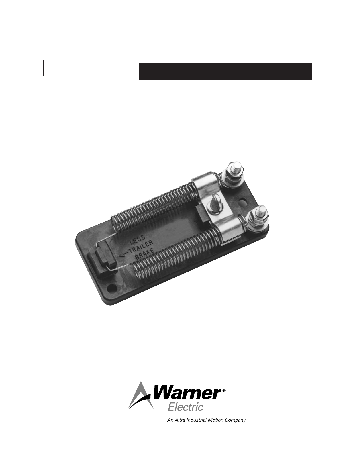
Resistor No. 1100-41
P-1376
819-0089
Installation & Operating Instructions
Page 2
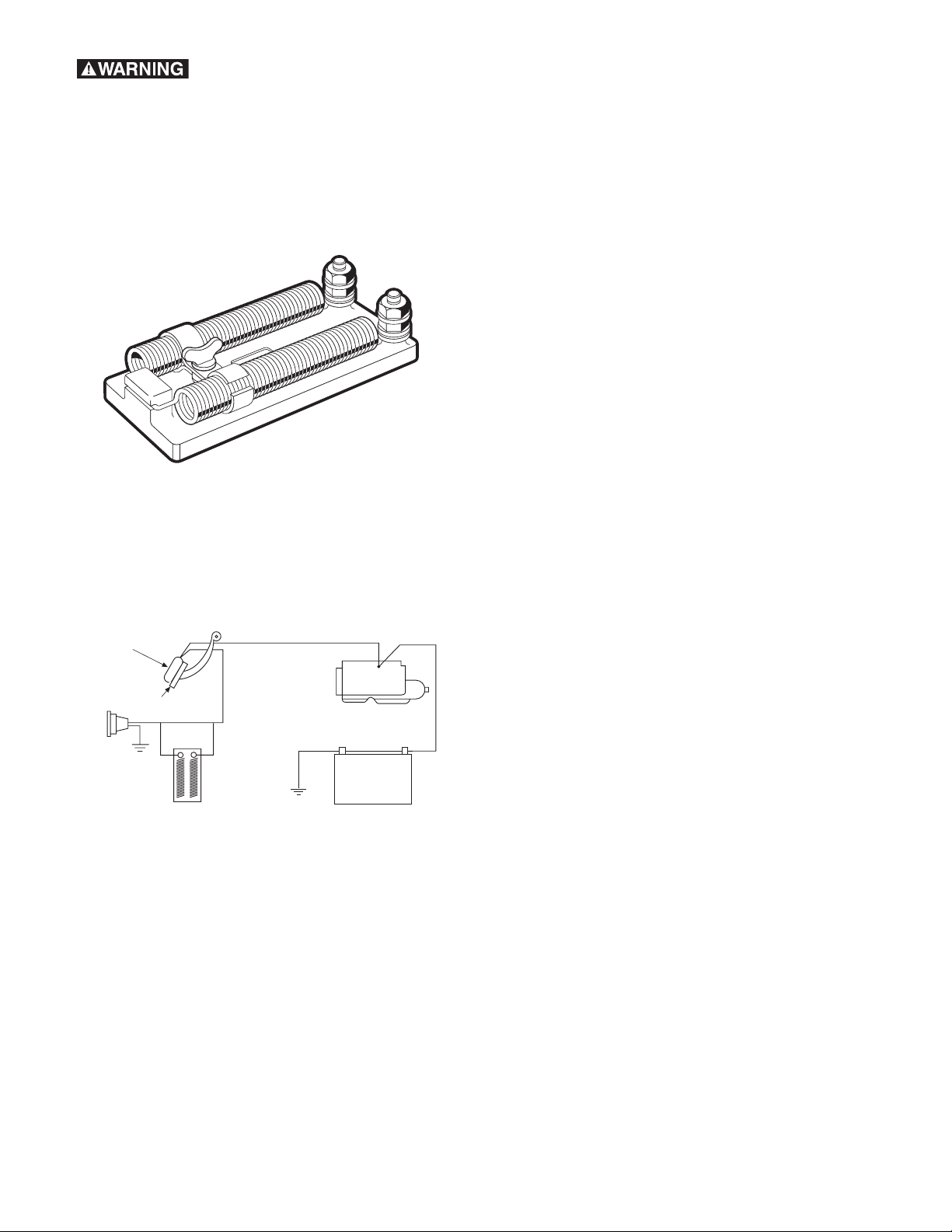
Failure to follow these
System resistor (optional)
Socket
Brake pedal
Battery
Starter
Foot controller
instructions may result in product
damage, equipment damage, and
serious or fatal injury to personnel.
Parts Included in Kit
System Resistor 1100-41
Typical Installation
Installation & Operation Instructions for
Warner Electric Brake System Resistor
1. The purpose of the System resistor is to allow
synchronization of trailer brakes with the towing
vehicle’s brakes. When properly adjusted each
brake system should do its own share of work.
The towing vehicle should not be stopping the
trailer and the trailer should not be stopping the
towing vehicle.
2. Select a suitable area in the engine
compartment. Mark the location for mounting
screws and drill (2) 3/16" holes. Position the
resistor and insert and tighten the two screws
to secure the unit in place.
3. Connect the resistor in series with the brake
control and power supply per the diagram.
4. Be careful when routing wires around hot or
sharp surfaces. Clamp wires to prevent
chaffing. A grounded or shorted wire would
make trailer brakes inoperable and could cause
damage to other wiring.
5. To increase braking power, loosen the thumb
screw and move slide toward “more trailer
brake”. To decrease braking power, move the
slide toward “less trailer brake”.
Warner Electric • 800-825-9050 P-1376 • 819-0089
2
Page 3
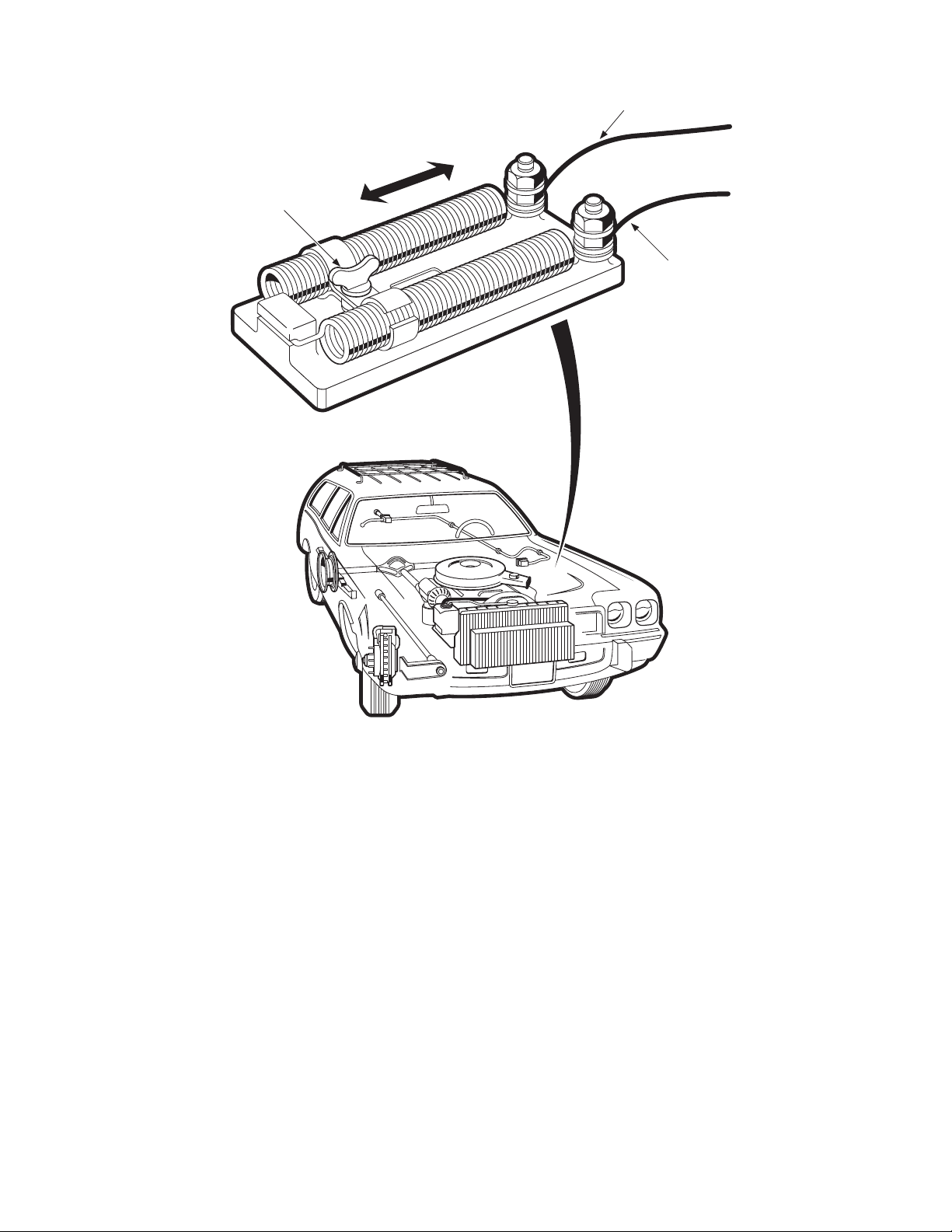
FROM
POWER
SUPPLY
TO BRAKE
CONTROLLER
ADJUSTMENT
THUMB SCREW
AND CLAMP
LESS
TRAILER
BRAKE
MORE
TRAILER
BRAKE
Warner Electric • 800-825-9050 P-1376 • 819-0089
3
Page 4

Warranty
Warner Electric LLC warrants that it will repair or replace (whichever it deems advisable) any
product manufactured and sold by it which proves to be defective in material or workmanship
within a period of one (1) year from the date of original purchase for consumer, commercial or
industrial use.
This warranty extends only to the original purchaser and is not transferable or assignable without
Warner Electric LLC’s prior consent.
Warranty service can be obtained in the U.S.A. by returning any defective product, transportation
charges prepaid, to the appropriate Warner Electric LLC factory. Additional warranty information
may be obtained by writing the Customer Satisfaction Department, Warner Electric LLC, 449
Gardner Street, South Beloit, Illinois 61080, or by calling 815-389-3771.
A purchase receipt or other proof of original purchase will be required before warranty service is
rendered. If found defective under the terms of this warranty, repair or replacement will be made,
without charge, together with a refund for transportation costs. If found not to be defective, you will
be notified and, with your consent, the item will be repaired or replaced and returned to you at
your expense.
This warranty covers normal use and does not cover damage or defect which results from
alteration, accident, neglect, or improper installation, operation, or maintenance.
Some states do not allow limitation on how long an implied warranty lasts, so the above limitation
may not apply to you.
Warner Electric LLC’s obligation under this warranty is limited to the repair or replacement of the
defective product and in no event shall Warner Electric LLC be liable for consequential, indirect,
or incidental damages of any kind incurred by reason of the manufacture, sale or use of any
defective product. Warner Electric LLC neither assumes nor authorizes any other person to give
any other warranty or to assume any other obligation or liability on its behalf.
WITH RESPECT TO CONSUMER USE OF THE PRODUCT, ANY IMPLIED WARRANTIES WHICH
THE CONSUMER MAY HAVE ARE LIMITED IN DURATION TO ONE YEAR FROM THE DATE OF
ORIGINAL CONSUMER PURCHASE. WITH RESPECT TO COMMERCIAL AND INDUSTRIAL
USES OF THE PRODUCT, THE FOREGOING WARRANTY IS IN LIEU OF AND EXCLUDES ALL
OTHER WARRANTIES, WHETHER EXPRESSED OR IMPLIED BY OPERATION OF LAW OR
OTHERWISE, INCLUDING, BUT NOT LIMITED TO, ANY IMPLIED WARRANTIES OF
MERCHANTABILITY OR FITNESS.
Some states do not allow the exclusion or limitation of incidental or consequential damages, so the
above limitation or exclusion may not apply to you. This warranty gives you specific legal rights and
you may also have other rights which vary from state to state.
Changes in Dimensions and Specifications
All dimensions and specifications shown in Warner Electric catalogs are subject to change without
notice. Weights do not include weight of boxing for shipment. Certified prints will be furnished
without charge on request to Warner Electric.
Warner Electric LLC
31 Industrial Park Road • New Hartford, CT 06057
815-389-3771 • Fax: 815-389-2582
www.warnerelectric.com
P-1376 • 819-0089 8/11 Printed in USA
An Altra Industrial Motion C ompany
 Loading...