

Page 1
Automatic Electric Brake
Foot Controller No. 1100-28
P-1386
819-0129
Installation Instructions
Page 2
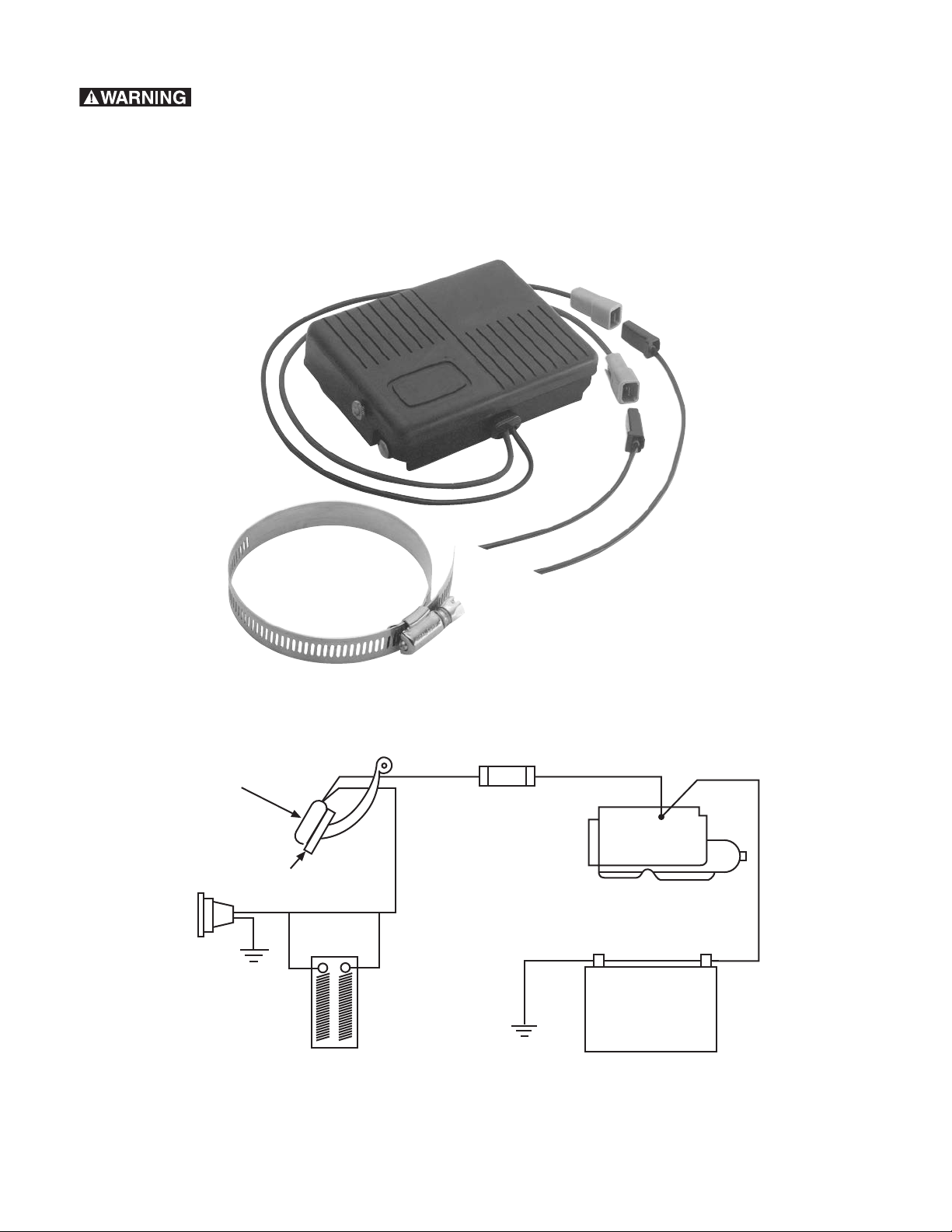
System resistor (optional)
Socket
Brake pedal
Battery
Starter
Foot controller
Fuse
(Not Provided)
Failure to follow these
instructions may result in product
damage, equipment damage, and
serious or fatal injury to personnel.
Parts Included in Kit
Typical Installation
Warner Electric • 800-825-9050 P-1386 • 819-0129
2
Page 3

Installation Instructions
1. Electrical connection is required for all
installations. Approximately 25 ft. of
automotive-type multi-stranded 14 gage or
heavier single wire with tough, thermoplastic
insulation meeting SAE standard J558a is
required.
Note: When towing a very light trailer,
Warner Electric System Resistor 1100-41
may be required to properly proportion
braking force between the trailer and the
towing vehicle.
2. Mount the controller on the brake pedal as
shown on page 4. Tighten it securely to the
pedal with the clamp provided in the kit.
Insert the connector end of one hook-up wire
segment into a matching connector
extending from the controller.
3. An electrical socket which mates with the
trailer power cable is to be installed in the
rear of the towing vehicle. Strip one end of
the hook-up wire and connect it to the brake
terminal of this socket.
4. Secure a single length of wire from the brake
connection of the socket to the underside of
the towing vehicle and route it to the engine
firewall. Position the wire to insure maximum
protection from scraping on the road surface
in rough terrain, flying stones, spray, etc. Also
avoid attaching wires near mufflers and
exhaust pipes. Wires should be clamped at
frequent intervals.
5. Remove a knock-out plug or cut a hole in the
firewall near the mounted controller.
Note: Solder or crimp clamp connections will
be required when connecting the controller
lead wires. Wrap electrician’s tape around all
bare wire joints. Do not use twist-type
connectors.
8. Making chassis ground connection is the next
installation step. Strip one end of the
remaining length of hook-up wire and connect
it securely to the ground terminal of the
socket at the rear of the towing vehicle.
9. Feed the wire under the towing vehicle to a
convenient chassis ground, such as a body
or chassis nut and bolt, battery ground post,
etc. Cut and strip the wire and attach it
securely to this ground.
A good ground connection
is essential for proper operation. It is the
responsibility of the installer to ensure a
good ground and that connections are
protected from the elements.
10. The power lead to the controller is last to be
connected. Strip one end of the hook-up wire
and feed it through a hole in the firewall from
the engine side. Solder or crimp this wire to
the remaining black controller lead.
Before proceeding, detach
one of the power cables from the towing
vehicle battery to prevent arcing.
Cut the hook-up wire to the proper length to
attach it to the live terminal of the starter
solenoid or relay, strip the wire and complete
the connection. Attaching this lead completes
your electrical connection. Reconnect the
towing vehicle battery cable.
6. Cut the wire to a proper length for reaching
the controller. Strip the wire and feed it
through the firewall hole.
7. Connect this wire to one of the lead wires
extending from the back of the controller.
Warner Electric • 800-825-9050 P-1386 • 819-0129
Tape together wires leading from the
controller and secure them to the steering
column or underside of the dash. Plug all
holes in the firewall with sealant or rubber
grommets to prevent exhaust gases from
entering through the holes and to protect the
wires from abrasion.
3
Page 4

Adjusting
knob
Lead wires
in front
Recommended
Lead wires in back
Adjusting
knob
Alternate
Recommended
Adjusting Your Controller
Controller knob adjustment – the pedal
mounted controller has a Trailer Brake Adjust knob
which affects the rate of application of the trailer
brake. This adjustment has no bearing on the
maximum braking capacity of the trailer brakes.
Because of the wide variety of towing vehicles and
trailers, it is necessary to balance the trailer brakes
with the towing vehicle brakes to provide for a safe,
comfortable stop. This adjustment should be made
to provide for a slight lead of the trailer brakes over
the tow vehicle brakes. Turning the handle
clockwise will decrease the rate of application of the
trailer brakes, while counter-clockwise will increase
the rate of application. When the desired setting is
reached, the controller will hold the adjustment but
may be varied at any time by rotating the knob as
described above. After this adjustment, there
should be no sensation of the trailer pushing the
tow vehicle during a stop, nor should there be an
excessive sensation of the trailer pulling the tow
vehicle during a stop.
Alternate
Warner Electric • 800-825-9050 P-1386 • 819-0129
4
Page 5

Warranty
Warner Electric LLC warrants that it will repair or replace (whichever it deems advisable) any
product manufactured and sold by it which proves to be defective in material or workmanship within a
period of one (1) year from the date of original purchase for consumer, commercial or industrial use.
This warranty extends only to the original purchaser and is not transferable or assignable without Warner
Electric LLC’s prior consent.
Warranty service can be obtained in the U.S.A. by returning any defective product, transportation
charges prepaid, to the appropriate Warner Electric LLC factory. Additional warranty information may be
obtained by writing the Customer Satisfaction Department, Warner Electric LLC, 449 Gardner Street,
South Beloit, Illinois 61080, or by calling 815-389-3771.
A purchase receipt or other proof of original purchase will be required before warranty service is
rendered. If found defective under the terms of this warranty, repair or replacement will be made, without
charge, together with a refund for transportation costs. If found not to be defective, you will be notified
and, with your consent, the item will be repaired or replaced and returned to you at your expense.
This warranty covers normal use and does not cover damage or defect which results from
alteration, accident, neglect, or improper installation, operation, or maintenance.
Some states do not allow limitation on how long an implied warranty lasts, so the above limitation may
not apply to you.
Warner Electric LLC’s obligation under this warranty is limited to the repair or replacement of the
defective product and in no event shall Warner Electric LLC be liable for consequential, indirect,
or incidental damages of any kind incurred by reason of the manufacture, sale or use of any defective
product. Warner Electric LLC neither assumes nor authorizes any other person to give any other
warranty or to assume any other obligation or liability on its behalf.
WITH RESPECT TO CONSUMER USE OF THE PRODUCT, ANY IMPLIED WARRANTIES WHICH THE
CONSUMER MAY HAVE ARE LIMITED IN DURATION TO ONE YEAR FROM THE DATE OF ORIGINAL
CONSUMER PURCHASE. WITH RESPECT TO COMMERCIAL AND INDUSTRIAL USES OF THE
PRODUCT, THE FOREGOING WARRANTY IS IN LIEU OF AND EXCLUDES ALL OTHER WARRANTIES,
WHETHER EXPRESSED OR IMPLIED BY OPERATION OF LAW OR OTHERWISE, INCLUDING, BUT
NOT LIMITED TO, ANY IMPLIED WARRANTIES OF MERCHANTABILITY OR FITNESS.
Some states do not allow the exclusion or limitation of incidental or consequential damages, so the
above limitation or exclusion may not apply to you. This warranty gives you specific legal rights and you
may also have other rights which vary from state to state.
Changes in Dimensions and Specifications
All dimensions and specifications shown in Warner Electric catalogs are subject to change without
notice. Weights do not include weight of boxing for shipment. Certified prints will be furnished without
charge on request to Warner Electric.
Warner Electric
31 Industrial Park Road • New Hartford, CT 06057
815-389-3771 • Fax: 815-389-2582
www.warnerelectric.com
P-1386 • 819-0129 8/11 Printed in USA
 Loading...