

Warner TCS-200-1, TCS-200-1H Service & Installation Manual
P-2003-2-WE
819-0420
TCS-200-1 and TCS-200-1H
Tension Controls
Service & Installation Instructions
An Altra Industrial Motion Company

Contents
Introduction ............................2
Theory of Operation ......................3
Technical Specifications ..................3
Installation
Control Mounting .....................4
External Sensor Mounting...............5
System Wiring ..........................5
System Start-Up and Adjustment ..........11
Voltage Tables .........................19
System Troubleshooting .................20
Component Parts List
Coupling, MCS-605-1 284-8000-003
Roll Pin (Drive) for Sensor Coupling 679-8001-067
TCS-200-1 Tension Control 6910-448-086
TCS-200-1H Tension Control 6910-448-087
Ultrasonic Sensor 4-40in 7600-448-001
List of Illustrations and Figures
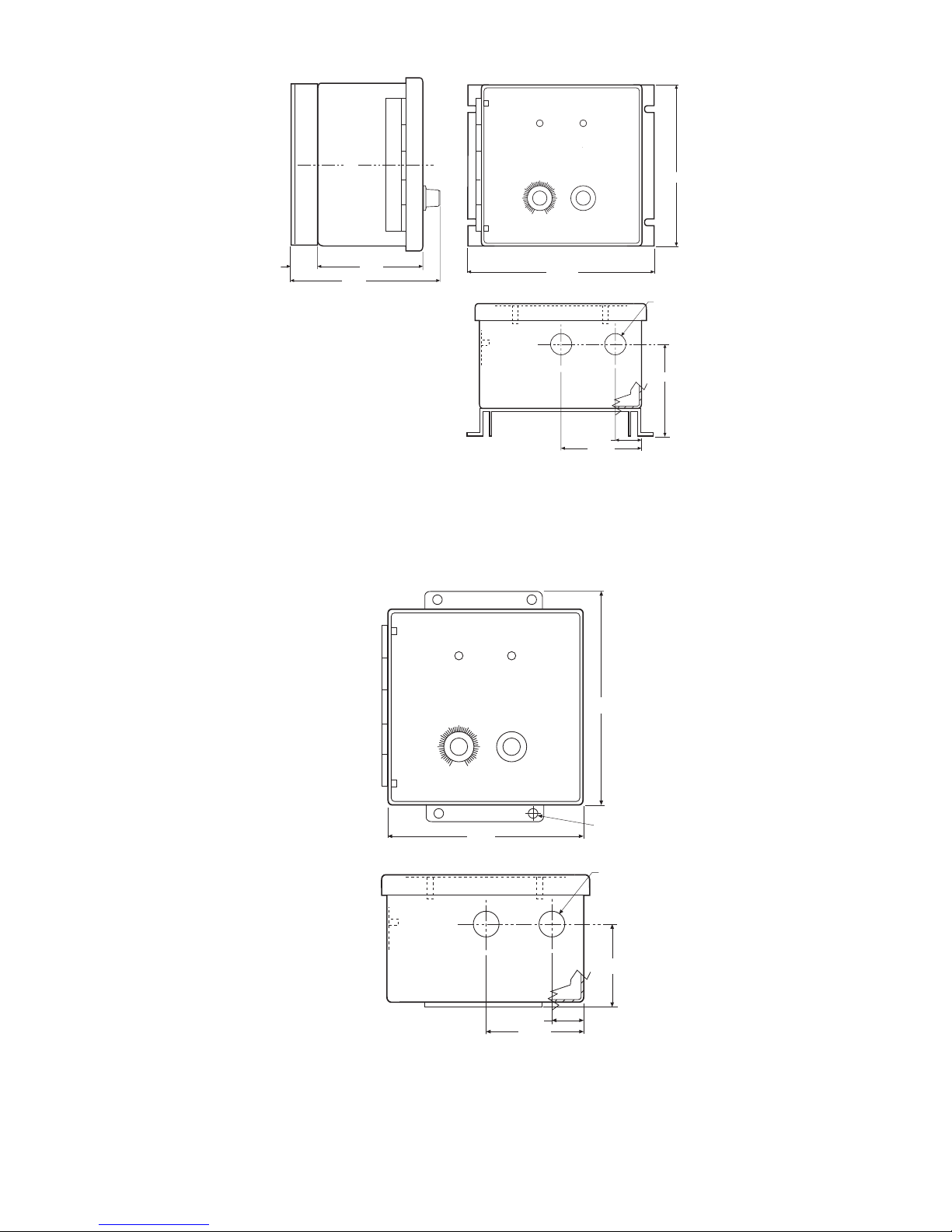
Figure 1 Dimensional Data, Mounting ....... 6
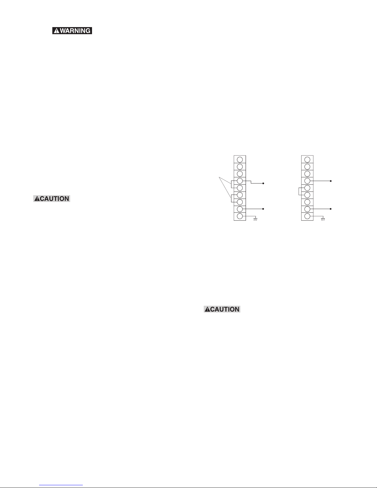
Figure 2 Power Connections .............. 7
Figure 3 Brake Connections ..............8
Figure 4 Remote Torque and Roll
Follower Connections ............. 9
Figure 5 Remote Switch, Analog Input and
Analog Input Isolation Connections . 10
Tables 1,2,3 Voltage/Current Tables .......... 19
Templates TCS-200-1H Template ........... 21
TCS-200-1 Template ............ 21
Introduction
The Warner Electric Tension Control system is
comprised of a tension brake, control module, and
optional external sensor input.
This manual has been designed to cover installation,
start-up, adjustment, and maintenance of your
tension control system and covers the control system
only. Further information on brake sizing and selection
can be found in catalogs P-1234 or P-771.
Power Source
The TCS-200-1 series Tension Controls operates
from a power source of 115 or 230 VAC, 50/60 Hz
input. Primary voltage is determined by the
customer’s input voltage source. The control is
factory set to accept 115 VAC input. Refer to the
wiring section for 230 VAC input connections.
Control
The TCS-200-1 series controls are selectable
voltage or current controlled power supply designed
to power up to a 16 magnet Electro Disc tension
brake system, Electromagnetic Particle Brakes,
TB series brakes or Advanced Technology tension
brakes. This control can be operated manually from
the front panel or remotely via an analog voltage
input, a current input, a remote pot, or a roll follower.
External inputs are also provided for remote brake
“off”, “run”, and “stop” functions, as well as front
panel control of these functions.
The analog voltage and current inputs are
electrically isolated from the main power circuitry of
the control when 15-35 VDC supply is provided to
maintain full isolation. If isolation is not needed, an on
board 15 VDC supply is jumpered to act as a default.
Sensors
When the TCS-200-1 series controls are operated
in a remote torque adjust mode, a 1,000 ohm
potentiometer is required. This should be a linear type
potentiometer with a rating of .5 watts, 10 percent
tolerance, and a .5 percent linearity.
For roll follower input applications, a 1,000 ohm
potentiometer with a rating of .5 watts, 10 percent
tolerance, and .5 percent linearity is required for best
performance.
Brakes
All 24 VDC tension brakes that Warner Electric offers,
to a maximum of 4.25 amps, can be used with the
TCS-200-1 tension control. For all 24 VDC tension
brakes that require greater current capability from the
control (not to exceed 5.8 amps), use a TCS-2001H. The brake converts electrical current supplied by
the control into torque, which retards material flow,
maintaining the desired web tension.
2 Warner Electric • 800-825-9050 P-2003-2 • 819-0420

Theory of Operation
When in operation, the control is powered by a
standard 115/230 VAC line. The control has a
transformer that converts that voltage to a level
suitable for any 24 VDC brake system. The signal is
rectified to DC and pulse width modulated (PWM) to
the desired brake current via the TENSION ADJUST
knob.
The front panel TENSION ADJUST feeds a small
voltage to a comparator, which compares this signal
to a triangular wave. This is where the PWM pulse is
generated. This pulse is then inverted and used to
drive a power circuit. The main brakes and a sense
brake are then energized by the power circuit at
regular intervals. From the sense brake, a growth and
decay signal is converted to a voltage that can be
added to the signal by setting a jumper on the inside
of the cover. This signal, when selected, is used to
maintain constant current to the brake. The signal
must not be selected when no sense brake is
connected.
The control has several options that allow for
external/remote tension adjust in addition to the
tension adjust pot on the front of the panel. Two such
options are the remote pot or a roll follower. Another
is the option for an analog input of voltage or current
from a PLC or ultrasonic sensor. A special feature of
the analog inputs is that they are optically isolated
from the rest of the control circuitry if an external
power source is used to power the isolated circuits.
The isolation is needed when using a PLC or an
external power supply for the ultrasonic sensor. An
internal power source is also available and jumpered
in as default if isolation is not necessary. The tension
adjust pot on the front of the panel becomes a span
adjust when any of the external control options are
connected.
The two indicators on the front of the panel are
green for “power on” and red to indicate a short
circuit. When a short occurs in the brake, the control
disables the power circuits to prevent damage. Turn
the switch to “off” to reset the short circuit indicator.
Because this is a basic tension control, no anti-residual
circuits, zero adjust circuits, or other complex control
circuits (found in other Warner Electric tension control
systems) are included in the TCS-200-1 series controls.
Technical Specifications
TCS200-1 and TCS200-1H
Input Power
115/230 VAC 50/60 Hz
Output TCS-200-1
Adjustable 0-24 VDC. Maximum of 4.25 amps
continuous. Can be used with any 24 VDC
tension brake with or without the need for a
sense coil.
Output TCS-200-1H
Adjustable 0-24 VDC. Maximum of 5.8 amps
continuous. Can be used with any 24 VDC
tension brake with or without the need for a
sense coil.
Ambient Temperature
-20° to 125° F (-29° to 51° C)
Fuse
2.5 Amp, 250 VAC, Slow-Blow
Protection
Internal short-circuit protection on driver output
stage
Sensor Inputs
• Remote Torque Adjust 1,000Ω
The control also has the capability to duplicate the
front panel selector switch at a remote location.
Brake “off” mode overrides the tension adjustment
and provides for resetting the short circuit indicator.
In the “run” mode, output operation is normal and is
controlled by any of the front panel or remote tension
adjust features discussed above. The brake “stop”
mode provides for full output current to the brake.
Warner Electric • 800-825-9050 P-2003-2 • 819-0420 3
• Roll Follower 1,000Ω
• Analog voltage input, 0-10 VDC (Optically isolated
when 15-35 VDC supplied from external source)
• Analog current input, 4-20mA (Optically isolated
when 15-35 VDC supplied from external source)

Auxiliary Inputs
• Brake Stop – Applies full voltage to the
connected brakes. Active high input.
o 1. If you are using a PLC or an
external power supply with this control, you must
enable the isolation of the control.
• Brake Run – Voltage to the brake is controlled by
any of the sensor inputs and/or the front panel
tension adjust. Active high input.
• Brake Off – Removes output current to the brake.
Puts the brake at zero current level. Active high
input.
Note 1: The remote input signal for these functions
requires a minimum contact rating of 20 VDC at .01
amps and a maximum of state leakage current less
than 100 micro-amps.
Note 2: The remote switch input overrides the front
panel switch.
Front Panel
• Tension Adjust – Provides current adjust to the
brake from 0 to 100%. In the remote and
analog input mode, provides for maximum output
level set to the brake.
• Brake Mode Switch –
Modes: “stop”-brake full on
“run” -normal operation
o 2. The TCS-200-1 cannot operate a single brake
or brakes that require more than 4.25 amps
continuous.
o 3. The TCS-200-1H cannot operate a single
brake or brakes that require more than 5.8 amps
continuous.
This Installation and Operation Manual has been
arranged for the systematic installation and start-up
of your tension control system. To achieve the best
possible results, we recommend checking off each
completed step in the space provided before
proceeding to the next step.
Sample
o Attach the TCS-200 control chassis to the
mounting surface and secure with mounting
hardware.
Check box after completing each step.
Control Mounting
“off” -brake off
Indicators (Front Panel)
• Green LED indicates AC power has been applied
to the control.
• Red LED indicates there is a short on the output.
Turn the front panel switch “off” to reset the short
circuit.
General
The control chassis must be considered NEMA 1
and should be kept clear of areas where foreign
material, dust, grease, or oil might affect control
operation.
Potentiometers (supplied by the customer)
• Remote Torque Adjust
1,000 ohms, 10% tolerance, .5% linearity,
.5 watts, linear taper
• Roll Follower – 1,000 ohms, 10% tolerance, .5%
linearity, .5 watts, linear taper
o 1. Determine a suitable location for the control to
be mounted. Consideration should be given to
whether the front panel adjustments will require
access by the operator.
o 2. Using the dimensional data supplied in Figure
1a and Figure 1b, drill four mounting holes using
a #16 drill if #8 through-bolts are used. For #8
capscrew mounting, use a #29 drill and tap holes
for #8 screws. Templates for hole drilling are
found on page 21.
o 3. Attach the TCS-200-1 or TCS-200-1H control
chassis to the mounting surface and secure with
mounting hardware.
Note: The control chassis has been designed to
accommodate two half-inch conduits for wiring when
the control is mounted to the machine frame.
4 Warner Electric • 800-825-9050 P-2003-2 • 819-0420

o 4. Attach conduit or seal tight connectors.
The control is now ready to be wired. Refer to the
wiring section of this manual for proper system wiring.
Brake Installation
Refer to the brake manual that is appropriate for the
brake selected for its installation procedures.
External Sensor Mounting (Optional)
Options for four types of external sensor inputs are
available. These consist of either an external torque
adjust, roll follower input that provides a signal
directly proportional to the diameter of the roll to be
processed, analog voltage, or analog current input.
Determine which type of external sensor will be
used and proceed to the appropriate section of this
manual.
Remote Torque Adjust Potentiometer (Optional)
Note: If angular rotation is not adequate, insufficient
output from the control is possible. In this case, a
timing belt drive between the roll follower pivot-point
and the sensor potentiometer may be necessary to
obtain adequate angular rotation.
o 2. Secure the roll follower potentiometer. This
completes the mounting for a roll follower
potentiometer. Refer to the wiring section of this
manual for proper control wiring.
Analog Input (Optional)
o 1. Select an appropriate mounting location for the
PLC or ultrasonic sensor.
o 2. Mount and secure the PLC or ultrasonic
sensor according to the specifications for those
products.
This completes the mounting. Refer to the wiring
section of this manual for proper control wiring.
o 1. Select an appropriate mounting location for the
external torque-adjust potentiometer.
Note: In determining this mounting location, take
into consideration the routing of the wires necessary
to connect the control, access for the operator,
and space required by the physical size of the
potentiometer.
o 2. Drill a mounting hole based on the bushing
diameter of the potentiometer selected.
o 3. Mount and secure the potentiometer.
This completes the mounting for an external remote
torque adjust potentiometer. Refer to the wiring
section of this manual for proper control wiring.
Roll Follower Adjust Potentiometer (Optional)
o 1. Mount the roll follower potentiometer and
determine the amount of angular rotation at the
potentiometer shaft.
System Wiring
System Wiring Precautions
The following wiring precautions will help you
properly wire and install a trouble free system.
o 1. Use a proper gauge wire for all wiring.
o 2. Insure that wires are cut and stripped so that
no excess bare wire is exposed.
o 3. Segregate AC input power from control
switching and external sensor wiring (if used).
o 4. Do not run AC power lines with DC power,
input sensor wiring, or switching wiring. Noise
transients can be easily transferred, causing
erratic control operation.
o 5. Use shielded cable when possible for
connecting the TCS-200-1 to external switches,
the sensor potentiometer, PLC’s, and ultrasonic
sensor.
Warner Electric • 800-825-9050 P-2003-2 • 819-0420 5
o 6. Under no circumstances should auxiliary
accessories be operated from the TCS-200-1
control.
WA RNER ELECTRIC
®
TCS-200-1H
POWER SHORT
TENSION
ADJUSTMENT
BRAKE MODE
.875 DIA. 2 PLCS.
FOR 1/2 CONDUIT
3.75
1.25
3.00
C
L
4.00
6.82
6.00
5.75
POWER SHORT
BRAKE MODE
®
6.00
.875 DIA. 2 PLCS.
FOR 1/2 CONDUIT
3.75
WA RNER ELECTRIC
TCS-200-1H
C
L
1.00
4.00
5.75
TENSION
ADJUSTMENT
6.82
TCS-200-1H with Heat Sink
Figure 1a
POWER SHORT
WA RNER ELECTRIC
TCS-200-1
TENSION
ADJUSTMENT
6.00
®
BRAKE MODE
1.25
3.00
7.50
.31 Dia.
6 Warner Electric • 800-825-9050 P-2003-2 • 819-0420
CS-200-1
Figure 1b
1.25
3.00
.875 DIA. 2 PLCS.
2.87
o 7. Do not attempt to incorporate
TB2
TB2
GNDGND
external switching schemes between two or
more brakes and the TCS-200-1 output. This will
damage the control and void the warranty.
o 8. Do not attempt to wire two or more controls in
parallel.
TCS-200-1 Series Controls Wiring
Refer to Figure 2 for actual wiring connections.
o 1. Unlatch the front cover of the TCS-200-1.
o 2. Connect one of the jumpers to terminals 5
and 6 of terminal block TB2 and discard the
spare jumper.
o 3. Connect the 230 VAC power to terminals 4
& 8 of terminal block TB2. Secure the terminal
screws.
o 4. Connect an earth ground wire between
terminal 9 of terminal block TB2 and an
unpainted metal surface of the control panel to
ensure a good ground connection. Secure the
terminal screw. Make sure the panel itself is
properly grounded.
Power
Determine if 115 VAC or 230 VAC will be used to
power the control and proceed to that section of this
manual.
Insure power is off and disconnects
open on the control panel before connecting the AC
input. Failure to do so can result in damage to
equipment and injury or even death to personnel.
115 VAC
Refer to Figure 2a for 115 VAC power input
connections.
o 1. Connect the 115 VAC power to terminals 4
& 8 of terminal block TB2 located in the base of
the TCS-200-1 enclosure. Secure the terminal
screws.
o 2. Connect an earth ground wire between
terminal 9 of terminal block TB2 and an
unpainted metal surface of the control panel to
ensure a good ground connection. Secure the
terminal screw. Make sure the control panel itself
is properly grounded.
FACTORY
INSTALLED
JUMPERS
1
2
3
NEUTRAL
4
5
6
7
8
9
115 VAC
HOT
INSTALL
JUMPER
1
2
3
NEUTRAL
4
5
6
7
8
9
230 VAC
HOT
a. 115 AC Power Wiring b: 230 VAC Power Wiring
Figure 2
Note: Do not apply power to the system at this point.
Brake
Determine the type of brake to be used with this
control and proceed to that section of this manual.
Insure connections are tightly secured.
Intermittent connection will cause the control to shut
down and output current to the brake will be
removed.
Electro Disc Tension Brake
230 VAC Input
Refer to Figure 2b for 230 VAC power input
connection.
o 1. Remove the factory installed jumpers from
terminals 4 & 5 and 6 & 7 of terminal block TB2
located in the base of the TCS-200-1 enclosure.
Warner Electric • 800-825-9050 P-2003-2 • 819-0420 7
Refer to Figure 3a for the Electro Disc Tension Brake
wiring connections.
o 1. Connect the red wire from one brake
magnet to terminal 1 of terminal block TB2 of the
TCS-200-1. This becomes the sense magnet.
 Loading...