

WarmYourFloor SunTouch P-3285 Instructions Manual

23055 Alcalde Drive, Laguna Hills, CA 92653
Toll Free 866 – 558 – 3369 ● Fax 866 – 558 – 2010
www.WarmYourFloor.com
CustomerCare@warmyourfloor.com
SunTouch P-3285 DualTemp Digital Outdoor Instructions
24v for use with CP ContactorPro Panels (CP-50/100/200)
To enter the parameter menu, press and hold the OK button for 5 seconds.
• Use the +/- keys to select the installation parameter to be adjusted.
• Press OK to toggle the parameter setting or to edit its value. When the value begins to blink, use the
+/- keys to adjust its value. Press OK to select the adjusted value.
• Toggle to “End” and press OK to exit the installation parameter menu.
• Parameters (Only Bold apply to Outdoor Patio Heating)
• J0: °C/°F Temperature display section.
• J1: Hot/Cold regulation mode. Select Hot for Heating, Cold for cooling.
• Cy: Proportional Integral regulation time cycle, value in minutes (default: 15 minute cycle).
• bp: Proportional Integral regulation band amplitude value in degrees °C/°F (default: 2.0°C/3.6°F).
• J4: NO/NC Normally Open or Normally Close actuator selection.
NC: If using an isolation relay and/or a relay box.
NO: if connecting to a Watts Zone Valve control.
• J5: Select PMP (Pump Maintenance Program) to perform a 1 minute exercise every day.
• J6: Air: Air (room) setpoint. Displays air temperature with floor low (FL) and high (FH) limits.
Flr: Floor (external sensor) setpoint. Displays floor temperature
without floor low/high limits. Air temperature is not a control
boundary.
Î Air temp is not used because the T-stat is mounted INSIDE and the
area to be monitored is OUTSIDE and monitored with Floor Sensor
Only
• J7: rEG (proportional Integral) or HYs (0.3°C Hysteresis) regulation type selection.
• Cp: Proportional Integral regulation temperature compensation value in °C/°F
• (default: 2.0°C/3.6°F).
• Ao: Air Sensor offset adjustment (default: no offset), display measure air sensor value.
• Fo: Floor sensor offset adjustment (default: no offset), display measure floor
• sensor value.
• FL: Floor temperature LOW limitation (default: 5°C/41°F), effective only if floor
• sensor present and set J6 to Air.
• FH: Floor temperature HIGH limitation (default: 28°C/82°F), effective only if floor
• sensor present and set J6 to Air.
• CLr: Press OK to reset to factory defaults.
• End: Press OK to exit installation parameters.
For Residential and Commercial Applications
07-3-857-40-02
Job Name
–––––––––––––––––––––––––––––––––––––––––––
Job Location
Engineer
Approval
–––––––––––––––––––––––––––––––––––––––––––––
–––––––––––––––––––––––––––––––––––––––––––––
–––––––––––––––––––––––––––––––––––––––––
Contractor
Approval
––––––––––––––––––––––––––––––––––––––––––––
–––––––––––––––––––––––––––––––––––––––––––––
Contractor’s P.O. No.
Representative
––––––––––––––––––––––––––––––––––––––––
DualTemp Digital Thermostat
Dimensions: 3-3/8" x 3-3/8"
The Watts Radiant DualTemp thermostat has the ability to sense
the temperature of the air, fl oor or a combination of air and fl oor.
Each DualTemp comes with an internal air sensor. An OPTIONAL
external 10k sensor which allows detection of fl oor temperatures may
be ordered separately. The external sensor does not have to be used if
the DualTemp is to detect air temperatures only.
DESCRIPTION PROPERTY
Operation Voltage 24V
Contact 10A, 230Vac Relay
Sensor NTC 10K Thermistor
Static Differential 1°F
Proportional 10 minutes for 3.5°F
Built-in manual setback 7°F
Air Temp Range 41- 99°F
Floor Temp Range 41- 99°F
°C °F
10 50.0
15 59.0
20 68.0
25 77.0
30 86.0
35 95.0
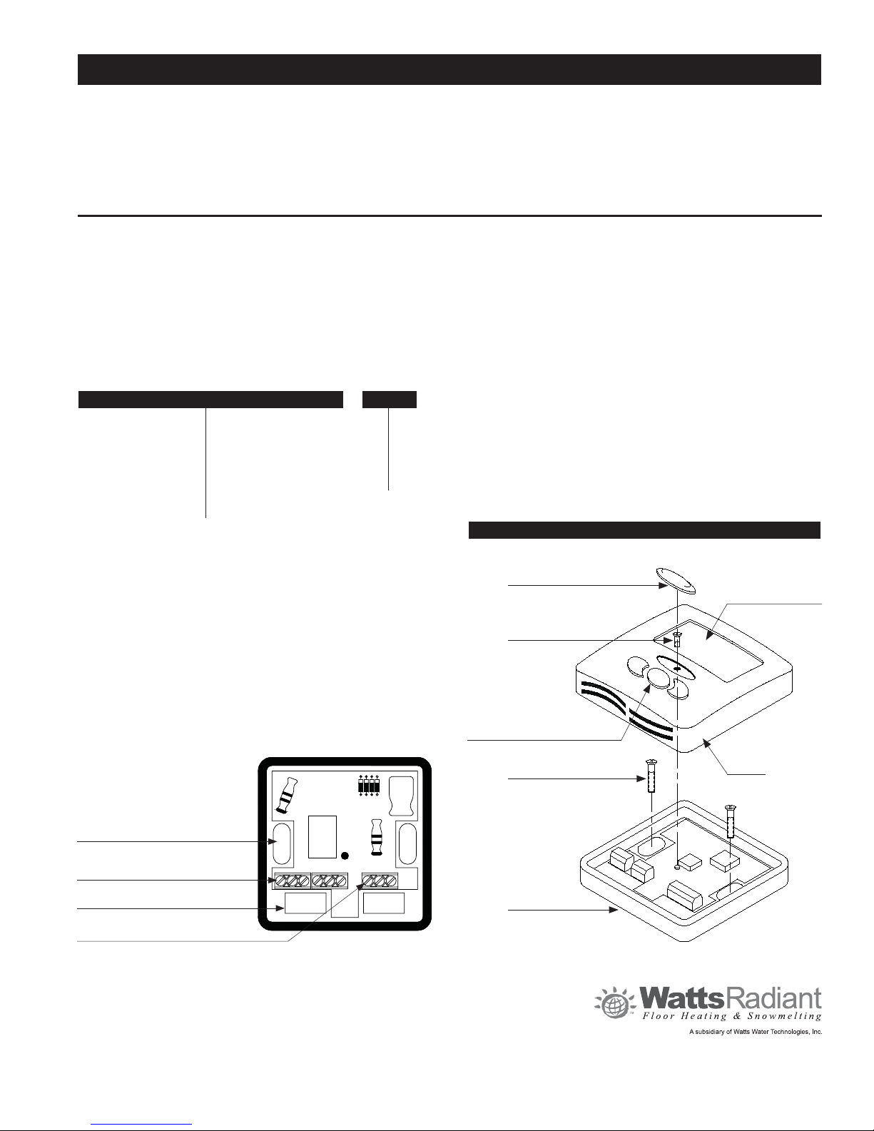
DETAIL VIEW
–––––––––––––––––––––––––––––––––––
Optional Floor Sensor
Installation & Operation
To mount the thermostat remove the thermostat cover by removing the
white Screw Cover (located in the center of the thermostat cover) and
the Cover Screw. Secure the Base Unit to the wall. Be sure to feed the
electrical wiring (18-3 or 18-4) through the provided slot in the Base Unit
and connect to appropriate terminal block(s). Replace the Cover, Cover
Screw and Screw Cover.
If fl oor sensing is desired, make sure the fl oor sensor is connected to
the corresponding fl oor sensor terminals (labeled NTC, the fi rst two
terminals on the right terminal block). It may be necessary to adjust the
J6 setting. See wiring diagrams for details.
Wall Anchor Point
Power Connections
Electrical Access
Optional Sensor Connections
4 4 2 2 6 7
NTC A/B
Screw Cover
Cover Screw
+/- Adjustment and
Temperature Set Buttons
Mounting Screw
Base
Digital Display
Cover
Watts product specifications in U.S. customary units and metric are approximate and are provided for reference only. For precise measurements,
please contact Watts Technical Service. Watts reserves the right to change or modify product design, construction, specifications, or materials
without prior notice and without incurring any obligation to make such changes and modifications on Watts products previously or subsequently sold.
 Loading...