

Page 1

TECHNICAL HELPLINES
US:1-888-927-6333
120 Volt USDW
Loose Wire
Installation Manual
The world’s best-selling electric oor heating brand™
IMPORTANT
Read this manual before attempting to install your heating
system. Incorrect installation could damage the cable and will
invalidate your warranty.
Page 2
Contents
Before you start
Do’s and Dont’s
Heating cable information
Making electrical provision for
the heating system
Master/Relay cheat sheet
Subfloor preparation and
technical notes
Preparation of wood or concrete
subfloor
Wiring configuration
Installing multiple heating
systems
Installation step 1
Installation step 2
Sizing Guide
Installation step 3
Installation step 4
Installation step 5
Limited Warranty & SafetyNet
Guarantee.
Terms and Conditions
WARMUP UNDERTILE
HEATING CABLE FOR
INSTALLATION IN
FLOORS.
Your Warmup® Undertile™
Cable has been designed so
that installation is quick and
straight forward. As with all
electrical systems, certain
procedures must be strictly
followed.
Warmup Inc, the manufacturer of the
Warmup® Undertile™ Heating System,
accepts no liability, expressed or implied, for
any loss or consequential damage suffered
as a result of installations which in any way
contravene the instructions that follow.
2
NA041-USDW-120-0807
3
17
16
15
14
13
12
10
7
6
4
18
22
19
25
24
23
Page 3
NOTE: Please ensure you do not damage the wire.
Be sure to test the system BEFORE you tile.
See pg 16 for more details.
Before you Start
Included with each Warmup heating system purchased should be the following:
• Primer
• Roller (to apply primer)
• Tape
• Installation Manual
• Thermostat
Double check your measurements and ensure you have the right cable sizes for the
area you need to heat. Bear in mind that the heating element should not be installed
under appliances or permanent fixtures and fittings such as refrigerators, washer/dryer,
cabinets, tubs, vanity units etc. Below is a quick reference guide:
120 VOLT LOOSE WIRE
If you are missing any of the box contents or believe you have the incorrect cables to
cover the area required, please call 888-927-6333 for assistance.
There will be other materials you need to complete the project which are not included
within the heating system. These include:
• Digital ohm multimeter - For heating cable testing.
• A 4” double gang electrical box (for the thermostat) - with a plaster ring
• Tile installation products and tools.
3
Cables
20 W 15 W 12 W
cable spaced at
2” 3” 4”
gives sq ft coverage of
USDW-360-120 15 22 28
USDW-360-120 22 32 40
USDW-360-120 33 47 62
USDW-360-120 44 64 84
Page 4

Do’s and Dont’s
DO use a qualified installer.
DO check the heating cable with OHM meter.
DO carefully read this installation manual before commencing installation.
DO ensure the floor surface is smooth, clean and dry before priming the floor
with Warmup
®
primer.
DO ensure good ventilation during application and drying of the thermal primer.
DO plan the heating system layout and installation so that any drilling after
tiling (e.g. for fixtures such as vanity units, tubs) will not damage the wiring.
Remember to keep a copy for future reference.
DO maintain a gap of min. 2”, max. 4” between the heating cable runs at all
times.
DO make sure that ALL heating cable is positioned under the tiles in the
installation.
DO protect the heating cable, including the joint, with cardboard or hardboard
between installation and tiling.
DO use thin set mortars and grouts (latex modified), suitable for use with
underfloor heating (this will be specified in the manufacturers’ instructions).
DO check that the heating cable is working immediately before commencing
tiling.
DO take particular care when tiling not to dislodge or damage the heating cable.
DO ensure that each tile is solidly bedded in tile adhesive, with no gaps or voids
beneath.
DO remember to install the floor probe for the Warmup
®
thermostat.
DO make sure all electrical work is done by qualified persons in accordance
with local building and electrical codes, the National Electrical Code (NEC),
especially article 424, Part V of the NEC, ANSI/NFPA 70.
DO Call the Warmup Technical Helpline: 888-927-6333 if necessary.
DO ensure that you have electrical provision to run the heating system at 120
VAC, depending on the system you’re installing.
DO remember to attach the rating labels included within this manual to the
circuit breaker and thermostatic controls.
DO sketch a diagram of the heating cable layout, which should be kept with the
manual for future reference.
4
Page 5

Do’s and Dont’s
DON’T attempt to connect the heating cables to any power source prior to
completion of installation.
DON’T install the heating cable under any built-in items (i.e. tubs, vanity units,
bookshelves, walls or partitions), or under any zero-clearance, dedicatedlocation furniture or appliances.
DON’T install the Warmup
®
Undertile™ Heating System under any floor other
than ceramic, quarry or natural stone tiles.
DON’T commence installation on a mud job/screed that has not been fully cured.
DON’T allow traffic over the primed floor or the installed heating cable before
tiling.
DON’T shorten the heating cable at any time.
DON’T allow the heating cables to cross over or touch each other at any point.
DON’T store tiles, sharp or heavy objects on any of the wiring while tiling or
bang a trowel on the installation area to remove excess mortar from the
trowel.
DON’T commence tiling before testing the Warmup® Undertile™ Heating System.
DON’T switch on the installed heating system until tile adhesive has fully cured
(1 - 3 weeks minimum), check adhesive manufacturer’s instructions.
DON’T clear grout lines with a utility knife.
DON’T install the heating cable on stairways, up walls or in closets.
DON’T attempt to repair the heating cable if it becomes damaged. Call the
technical helpline for further instruction: 1-888-927-6333
5
Page 6
Heating cable information
The heating cables consist of a fixed length of heating cable terminated at one end with
9’ of unheated lead. We recommend you do not alter the length of the unheated lead,
however if necessary, the wire can be extended if a UL-approved wire and connector box
suitable for the purpose is used (e.g. waterproof if going into the floor, etc.). This must be
carried out by a qualified electrician in accordance with local/state laws and guidelines.
Inspect the entire heating cable for damage, this includes the factory made joint and end
termination. The joint and end termination cannot be altered or remade if damaged. If
any parts are damaged contact the technical helpline (888-927-6333).
The core and ground braid are factory joined in a water resistant joint assembly to each
supply conductor and ground conductor of the unheated lead.
The Warmup Undertile™ Heating Cable is (File No. E303230).
120 VOLT LOOSE WIRE GUIDE
Warmup Heating Cable is designed for use with ceramic, quarry or
natural stone tiles. Use the Warmup Carbon Heating System for
heating under laminate, engineered wood or any other non-hardsurface
flooring.
Number of heating
cables per
15A supply point
Model Wire color Length (ft) Wattage (W) Amps (A) Resistance (Ω)
5 USDW-360-120 GREY 66 360 3.0 40.2
3 USDW-480-120 RED 99 480 4.0 30.2
2 USDW-720-120 BLACK / ORANGE 155 720 6.0 20.1
1 USDW-950-120 BLACK / GREY 216 950 8.0 15.2
6
Page 7
Making electrical provision for the heating system
For each Warmup® Heating cable you install, you will have 1 unheated lead running from the floor
to the thermostat’s electric connection. The joint connecting the unheated lead to the heating
cable must be at least 2 inches from the wall and placed in a position to be covered by tile and thin
set mortar.
It may be necessary to chisel out short channels in the subfloor to minimize the increased height
presented by the floor probe and the unheated lead.
All electrical connections should be done by a qualified technician.
Install to NEC and local BOCA codes.
Separate conduit will be required to run the unheated lead and the sensor wire back up to the
thermostat. Please note that they cannot be placed within the same conduit. Neither the unheated
lead or sensor wire must cross, or come into contact with, the heating element. Bear in mind that
you will need to make provision for drawing the unheated lead and sensor wire up through
the conduit to the control box.
Electrical Requirements
Please refer to the table on page 6 to calculate the amperage load for your particular system.
For smaller areas, you may be able to utilize an existing circuit. In most cases, however, you
will need a separate circuit to power the Warmup heating cables.
The Warmup thermostat has a maximum resistive load of 15 amps (i.e. a maximum of 2 x USDW800).
It also includes a built-in GFCI. If you want to control more than 15 amps worth of heating via a
single thermostat you will need to use Warmup’s master / relay configuration. Instead of using the
thermostat, a different model of master thermostat is used to control individual switching units
(each capable of switching up to a 15 amp load, and each containing its own GFCI). The relay units
require their own separate electrical feed, and up to 10 relay units can be daisy chained to a single
master unit via low voltage cabling. For further information please call the Warmup Helpline or
visit www.warmup.com.
The thermostat should be connected to the main electrical supply via a fuse or circuit in accordance
with the National Electrical Code. If the thermostat used does not include a built-in Ground Fault
Circuit Interrupter (GFCI), then one must be added to the circuit between the main power supply
and the thermostat. If the thermostat does include a GFCI, it is NOT recommended to include
another in the circuit, as this may cause accidental tripping of the control unit.
Ensuring Safety
Install the Warmup thermostat within the same room as the heating cable. In order to ensure the
efficient running of the system within bathrooms, we recommend that the controls are located
at least 36 inches away from shower openings or basin back splash areas so you minimize the
possibility of exposure to water.
The rating label in this manual must be attached to the circuit breaker box for referral by the
homeowner or electrical inspector. An additional smaller label is attached to the manual to be
fixed adjacent to or on the thermostatic control.
7
Page 8

Making Electrical Provision for the heating system
8
Do make sure all electrical work is done by qualified persons in
accordance with local building and electrical codes, the National
Electrical Code (NEC), especially article 424, Part V of the NEC,
ANSI/NFPA 70.
Page 9
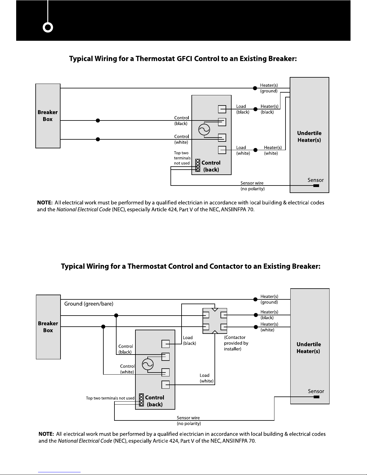
Making electrical provision for the heating system
9
Dedicated 110 – 120V
Circuit as per NEC
Ground (green/bare)
Live (black) (L1)
Live (black) (L1)
(white) (L2)
(white) (L2)
NOTE: Wiring for L1 is usually black (live) and wiring for L2 is usually white (as used for Neutral).
NOTE: Wiring for L1 is usually black (live) and wiring for L2 is usually white (as used for Neutral).
Dedicated 110 – 120V
Circuit as per NEC
Contactor
110 –
120V
Max. 16 amps
Page 10
Master/relay cheat sheet
10
Master/Relay Cheat Sheet:
Disclaimer:
This sheet does not preclude or eliminate the need to read either the “Warmup Undertile Heater Installation Manual” or the installation
instructions provided with the thermostats. This represents a breakdown of the material contained in the Master and Relay installation
instructions, but is not a replacement for those directions. If you have any questions regarding the product or installation, please call
(888) 927-6333, and
one of ou
r customer service representatives will be happy to assist you.
1. Each Slave (Relay) connects to 1-2 heaters
a. Heaters are connected via the outside wires marked load (one black, one white) on the
back of each Slave (Relay).
b. The other two wires are marked 120VAC (one black, one white) and are
connected to the dedicated circuit of 16 amps provided for
each individual slave.
c. Connect Ground (green/bare) to line from home.
2. To connect Slaves (Relays)/Master Thermostat:
a. This process requires using the terminals inside the Slaves (Relays) that are found by
removing the face of each unit
.
b. A sticker sits above this terminal labeled 1-4
i. 1 and 4 are labeled “GND” for ground
ii. 2 is labeled “Drive”
iii. 3 is labeled “+12V”
c. The Wiring
i. braided 18-22 gauge wire is required (to be supplied by a certified electrician)
ii. Wiring is a “daisy chain,” requiring you to wire Slave (Relay) to Slave (Relay)
to Slave (Relay)…. etc.
1. Wire “GND” 1 to “GND” 1
2. Wire “Drive” to “Drive”
3. Do not wire the second “GND” connection (marked under #4) - it will
not be used. Also, do not use the “12VDC” connection as this will be
used in the final wiring.
4. Steps 1-3 apply to all Slave (Relay) connections.
5. Final Slave
hookup to Master Thermostat
a. The final slave that connects directly to the Master Thermostat is
wired the same as in Step 2. In addition, the connection marked
“12VDC” must also be wired to the Master Thermostat (refer to
diagram).
i. This last connection is what provides power to the
programmable Master Thermostat.
ii. This requires no additional circuit or connections.
b. The bottom two connections that are marked with a symbol (a
circle surrounds a jagged line, refer to diagram) is connected to
the floor probe
i. Floor probe must be at leas
t 12 inches into the floor
ii. Must have at least a 1-inch clearance on either side from
heater wires.
Page 11
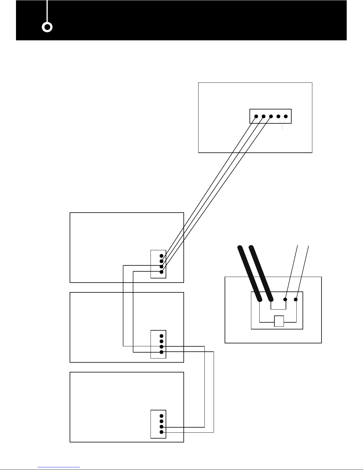
11
1 2 3 4 1 2 3 4
1 2 3 4
DNG
EVIRD
V21+
DNG
DNG
EVIRD
V21+
DNG
DNG
EVIRD
V21+
DNG
DRIVE
+12V
GND
PROBE
CT230-120GA/
TH115-F-12VDC
Master/Relay Wiring
Front Front
Front
Back
Back
)s(retaeh roolf morf eviL
rekaerb tiucric morf eviL
rekaerb tiucric morf
L2
)s(retaeh roolf morf lartueN
Models Adressed:
CT230-120GA
TH115-F-12VDC
CT230-120GA/CT230-120GA/
Load
120VAC
CT230-120GA/
Connections from models CT230-120GA/CT230-240GA
to other CT230-120GA/CT230-240GA or to the
Master Thermostat TH115-F-12VDC are made using
18-22 Gauge stranded conductor wire.
IMPORTANT:
Page 12
Subfloor preparation - technical notes
To fully utilize the long-term durability of ceramic tiling, whether heated or not, it is important that
the design, construction and preparation of the subfloor is carried out correctly.
It is essential that the sub-floor be sufficiently rigid to support the ultimate weight that it will have
to bear without movement or deflection.
The choice of products for subfloor preparation and tile will vary depending on the existing
subfloor, preferred tiling system and choice of tile. This document is only intended to be an outline
guide to laying ceramic floor tiles. Further help regarding floor preparation and tile application is
available from the tile adhesive manufacturers and/or the Tile Council of America (TCA) Tel: 864646-8453, website: www.tileusa.com. Alternatively, you may wish to seek professional advice e.g.
an architect/contractor.
Subfloor Preparation
Prior to installation, it is important that the subfloor is properly prepared as per Tile Council of
America Guidelines.
WOOD SUBFLOOR: Boards need to be of suitable material or requires backer board. Chipboard and
O.S.B. boards (flake boards) are not suitable bases for ceramic floor tiling.
SUBFLOOR PREVIOUSLY COVERED IN LINOLEUM, CORK OR CARPETING: All old flooring and
adhesive must be removed. If bitumen is present as adhesive residues it must be removed. If the
bitumen is a damp proofing membrane or isolation membrane it must be covered with a minimum
2” of sand/cement self leveler, taking care not to puncture the bitumen coating. If using other
damp proofing or tanking systems, contact the manufacturer for advice.
We strongly recommend installing tile and stone flooring according to manufacturer’s recommendations, TCA
guidelines and ANSI specifications.
Special Precautions
MOSAIC TILE AND PORCELAIN: When installing mosaic tile and CERTAIN PORCELAIN, we
recommend a two-step process. Cover the heating cable with latex self-leveling compound before
tiling to ensure a flat, smooth surface, then thin set the mosaic according to typical practice.
EXPANSION JOINTS: Do not install the heating cable through an expansion joint. Install the heating
cable right up to the joint, if necessary, but do not bridge the joint.
INSULATION: Do not install rigid insulation directly above or below backer board or mortar.
If possible, install insulation as shown in diagrams.
Insulation dramatically enhances the performance and efficiency of floor warming systems.
12
Page 13
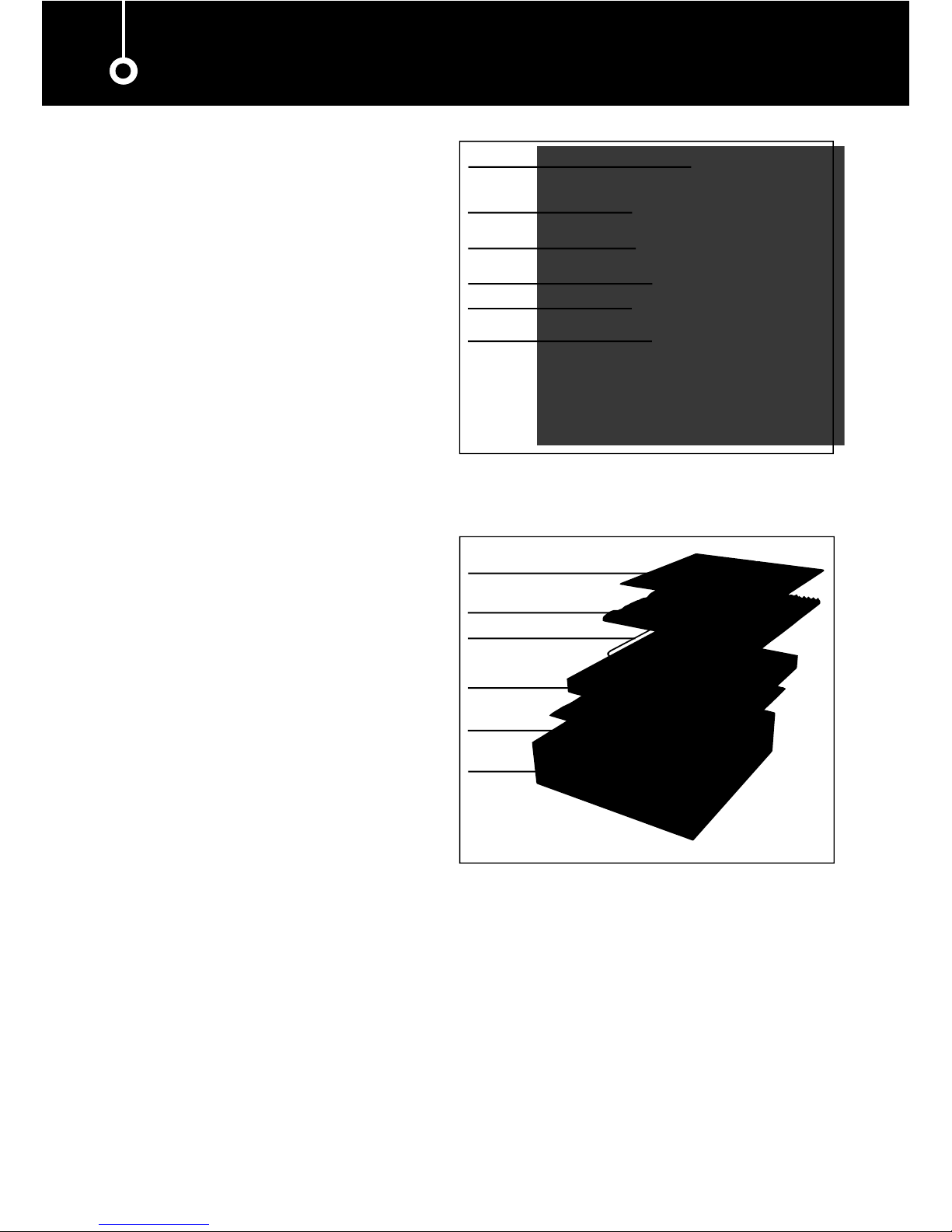
Preparation of wood or concrete subfloor
Ceramic tile
Flexible tile adhesive
Flexible tile adhesive
Heating wire
Cement Backer board
Timber
floor boards
Installation
onto wood floor
Timber floors
The above is for use as a general guideline only.
Installations and subfloor work must be as per
Tile Council of America Guidelines.
Using cement backer board:
Ceramic tile
Fix the cement backer board as per
Boards must be overboarded by
a suitable tile-backer board.
manufacturer’s instructions.
Flexible tile adhesive
Heating wire
Cement
Backer board
Tile backer board
adhesive
Concrete
sub-floor
Regardless of the type of subfloor, it is
important to ensure that the thin set
mortar and grout used are latex modified
and that the tile backer/ construction
board has been fitted as per the
manufacturer’s instructions. High quality,
Portland-based mortars that are latex
modified are most suitable.
10
The Heater wire installation shall be in
accor
dance with one of the illustrated
methods as per this manual. The heater
wire is not intended to be installed
directly upon the subfloor.
13
Preparation of wood or concrete subfloor
Page 14
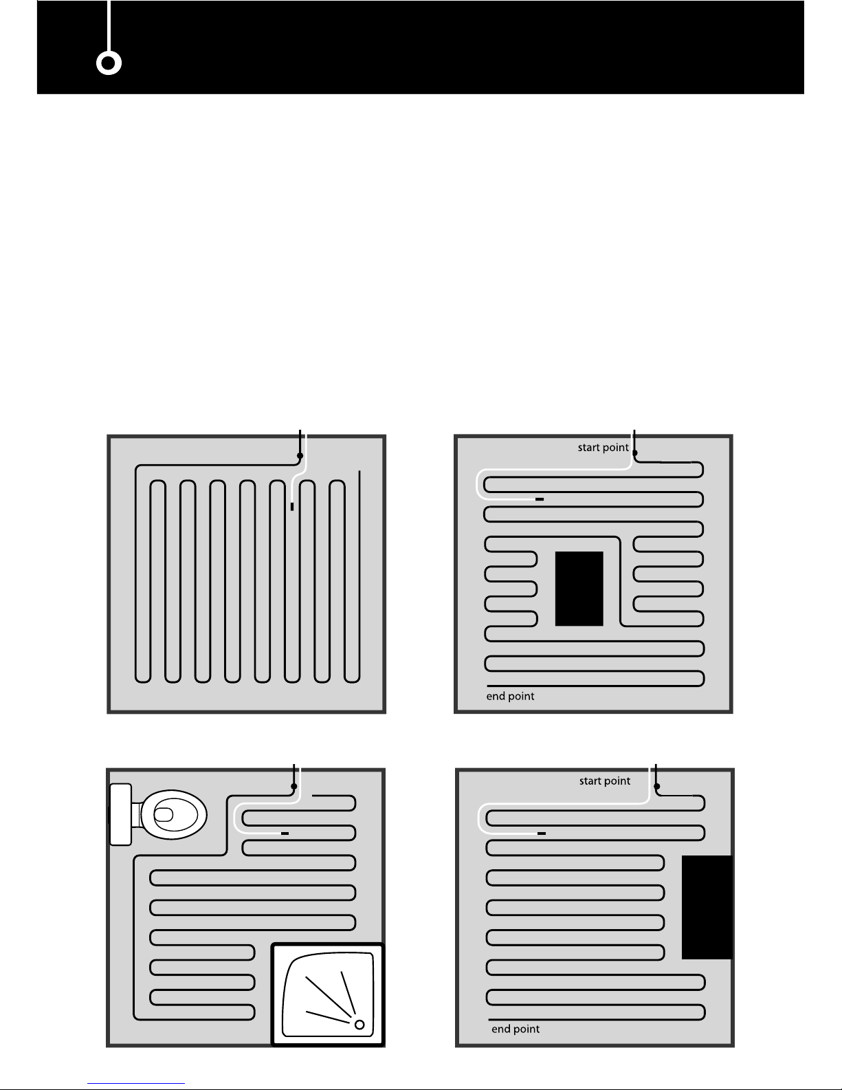
Wiring configurations
Before installing the heaters, refer to the sizing guide on page 18 of this booklet to ensure
you have the proper number and size of heaters for the area you wish to heat. The sizing
guide will also give you the perimeter and heating wire spacing required for your particular
r
oom size.
While the installation instructions only make provision for the wiring to be installed in a set
configuration, there are many instances where departure from this configuration may be
desirable. Below are a few drawings illustrating the versatility of the Warmup® Undertile™
Heating System.
In each of the examples, the floor space is heated using different wire configurations to suit
the particular layout of the room. It should be noted that while the sizing chart provided in
this booklet is a useful guide to heater layout, it may be necessary to slightly alter the heating
wire spacing
to suit your particular installation. However, at no time should the spacing between
the wires be less than 2” or greater than 4”.
unheated lead unheated lead
start point
eborp roolf
floor probe
end point
Standard room Room with central obstacle
floor probe
unheated lead
start point end point
unheated lead
floor probe
Bathroom Standard room with recesses
11
The heating cable shall not extend beyond the room or area in which it originates.
14
Wiring configurations
Page 15

Installing multiple undertile heating cables
When installing two or more cables, begin by reading the sizing guide on page 18 of
this booklet to ensure ou have the proper number and size of cables for the area
you wish to heat. The sizing guide will also tell you the perimeter and heating cable
spacing required for your particular room size.
After you prime the subfloor, mark the subfloor as per the instructions on page 17 and
lay the first cable. Do not cover the first cable with tape at this point as you may wish to
slightly alter the spacings later on. Lay the second cable in the remaining area using the
same perimeter and heating cable spacings as the first cable and test the second cable.
When laying more than one cable, it is important to keep these points in mind:
1. The heating cables may not touch or cross at any point.
2. The heating cables are joined in parallel only at the Thermostat. Do not attach one
cable to another in series.
3. The heating cable spacings for all cables in an area should be approximately equal.
15
Page 16
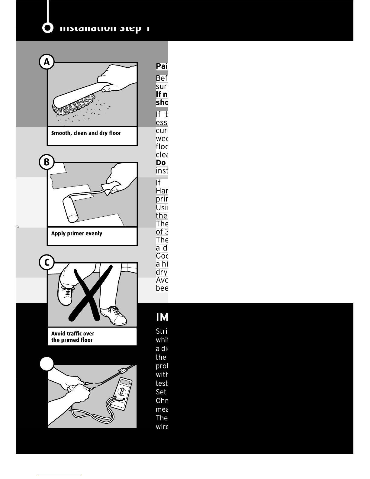
Paint the subfloor with Warmup® primer*.
Before applying the primer ensure that the floor
surface is smooth, dry and free from dust or grease.
If necessary, an appropriate smoothing compound
should be applied and allowed to cure.
If the cable is being fitted to a solid floor it is
essential that the concrete slab has been allowed to
cure before the primer is applied. This can take 8
weeks or more. If tiling on existing ceramic or quarry
floor tiles, clean the floor with an appropriate floorcleaning compound.
Do not apply the green Warmup® primer; go to
installation step 2.
If tiling on water proof/resistant surface (ie
Hardibacker) do not apply the green Warmup®
primer; go to installation step 2.
Using the roller supplied, apply the primer evenly to
the entire surface to be heated.
The primer must be allowed to dry for a minimum
of 3 hours.
The light green color of the primer will change to
a darker green once dry and will be slightly sticky.
Good ventilation must be provided which, along with
a higher ambient air temperature, will accelerate the
drying process.
Avoid traffic over the subfloor once the primer has
been applied.
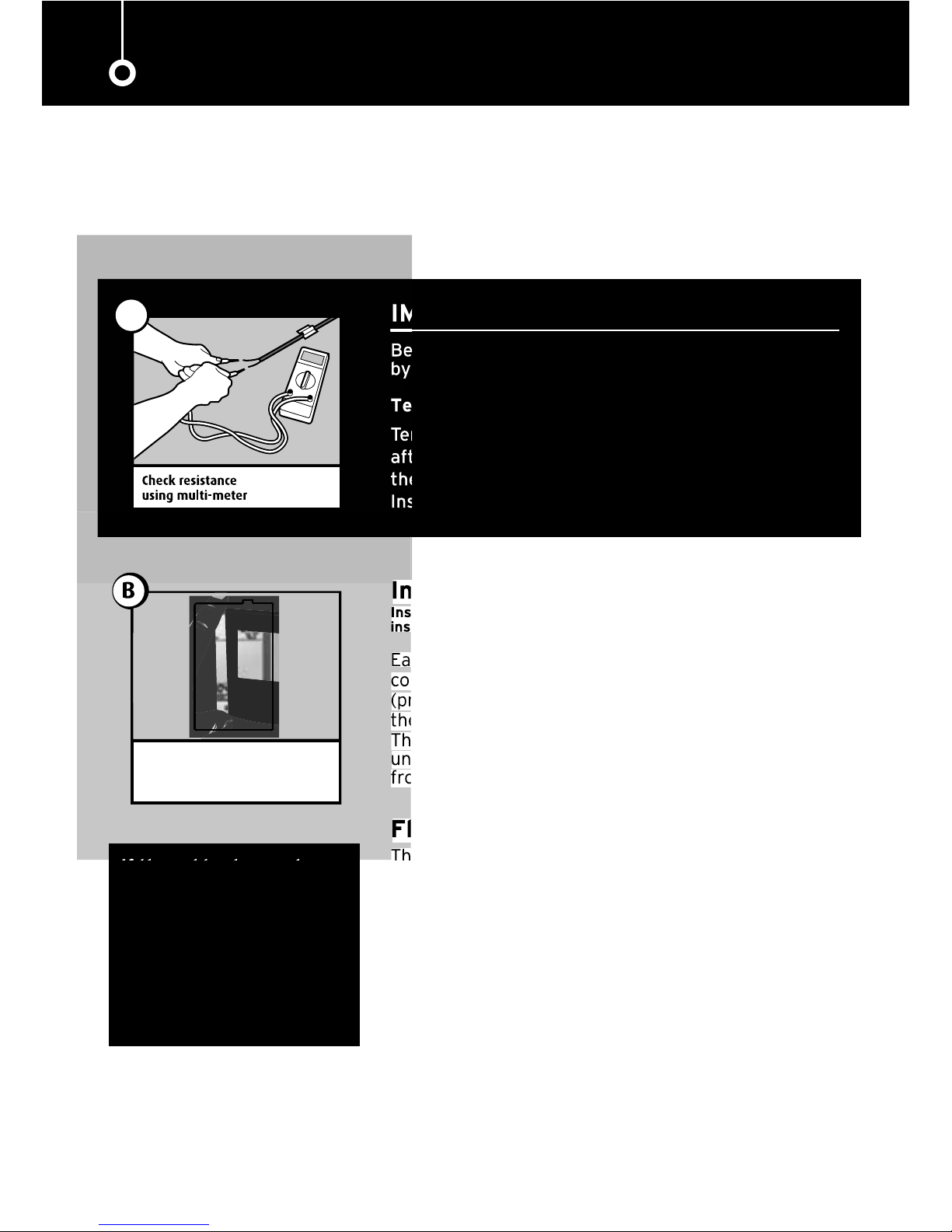
IMPORTANT! – Test the cable
Strip the ends of the cold lead wire and test the black &
white cables to ensure the cable is working properly. Using
a digital ohmmeter or multi-meter, check the resistance of
the heating cable and continuity of the
protective ground braid. Please note that analog meters
with a moving needle are not sufficiently accurate for
testing the Warmup cable.
Set your Ohm meter to measure resistance in 0 – 200
Ohms. Acceptable readings of these ohms resistance
measurements
There should NOT be any continuity between the ground
wire and either of the white neutral wire or the black live
wire. Any continuity indicates there is a short in the circuit.
*If the cable is being fitted to a wooden floor, the floor should be boarded over with tile
backer board or 3/4” plywood or Warmup® Insulation Board.
Installation Step 1
the entire surface to be heated.
testing the Warmup cable.
the heating cable and continuity of the
D
Test your heating cable
16
Page 17
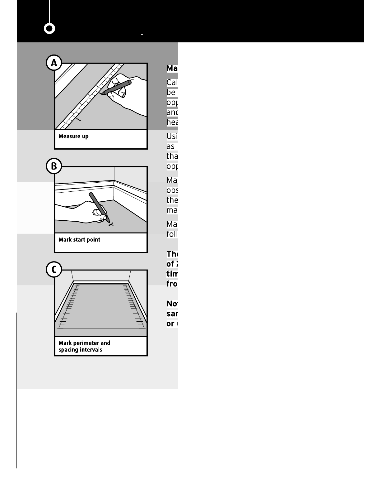
Mark the cable position on the floor.
Calculate in square feet the size of the area to
be heated. Then, using the sizing guide on the
opposite page, refer to the heating cable spacing
and perimeter distances to correctly fit your
heating cable into the space available.
Using a fiber tipped pen, mark a start point as close
as possible to the power supply, but no further
than 8 feet from it using the sizing guide on the
opposite page.
Mark all the outer corners of the heated area
observing the perimeter distances referred to in
the sizing guide and join the corners up to form a
marked out perimeter.
Mark up the spacing intervals for the heating cable
following the sizing guide.
The spacing between cables must be a minimum
of 2” apart, but not further than 4” apart. At no
time, should the heating cables be less than 2”
from the wall.
Note: The entire system must be kept on the
same level; do not lay the cables on stairways
or up walls.
17
Installation Step 2
the sizing guide and join the corners up to form a
than 8 feet from it using the sizing guide on the
from the wall.
time, should the heating cables be less than 2”
Page 18
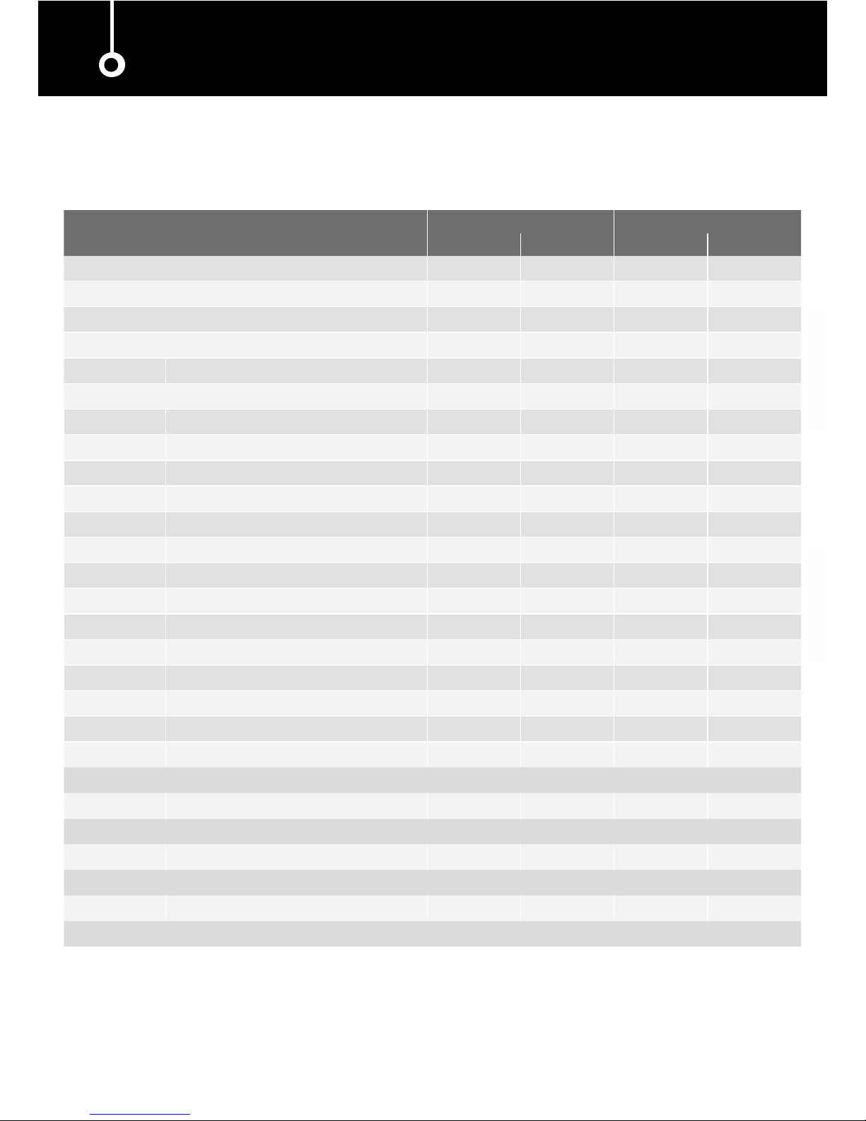
Sizing guide
18
If your area is above 120 ft, please contact the Warmup Technical Helpline
on 888-927-6333 for assistance.
NOTE: All spacing has been based on square areas for calculation purposes.
Therefore, actual spacing will vary according to the shape of the area to be
heated.
Area (sq ft) Heaters
Spacings Perimeter
mm in mm in
15-16 CADWS-360 57.2 2¼ 50 2
17-18 CADWS-360 69.9 2¾ 50 2
19-20 CADWS-360 81.0 3¼ 50 2
21-24 CADWS-360 101.6 4 50 2
25-26 CADWS-480 69.9 2¾ 50 2
27-29 CADWS-480 81.0 3¼ 50 2
30-32 CADWS-480 63.5 2½ 50 2
33-34 CADWS-480 101.6 4 50 2
35 CADWS-720 57.2 2¼ 50 2
36-41 CADWS-720 69.9 2¾ 50 2
42-44 CADWS-720 81.0 3¼ 50 2
45-49 CADWS-950 57.2 2¼ 50 2
50-56 CADWS-950 69.9 2¾ 50 2
57-59 CADWS-950 81.0 3¼ 50 2
60-68 CADWS-480+CADWS-720 69.9 2¾ 50 2
69-72 CADWS-480+CADWS-720 81.0 3¼ 50 2
73-74 CADWS-480+CADWS-720 88.9 3½ 50 2
75-78 CADWS-950+CADWS-480 69.9 2¾ 50 2
79-87 CADWS-950+CADWS-480 81.0 3¼ 50 2
88-89 CADWS-950+CADWS-480 88.9 3½ 50 2
90-92 CADWS-720+CADWS-950 69.9 2¾ 50 2
93-98 CADWS-720+CADWS-950 76.2 3 50 2
99-104 CADWS-720+CADWS-950 81.0 3¼ 50 2
105-106 2xCADWS-950 69.9 2¾ 50 2
107-112 2xCADWS-950 76.2 3 50 2
113-119 2xCADWS-950 81.0 3¼ 50 2
120 UPWARDS Call Warmup
Page 19
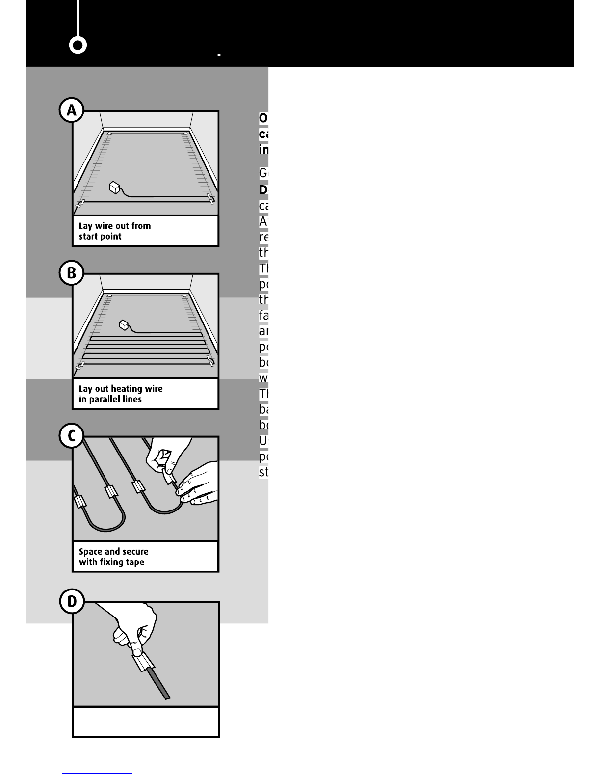
Installation step 3
Once the floor has been marked up, the heating
cable can be laid out. Test the cable throughout
installation.
Gently pull the unheated lead from the box.
Do not remove the spool from the box as this will
cause the heating cable to twist.
After 9 feet of cable has been removed, you will
reach the point at which the unheated lead joins
the heating cable.
The joint should be taped to the floor at the start
point. Ensure that the factory joint lays flat on
the floor. Care should be taken to ensure that the
factory joint remains horizontal, and within the
area to be tiled. The joint should not be bent at
point of entry into the conduit as this may damage
both the factory joint and /or the heating element
within.
The heating cable should be laid in parallel lines
back and forth across the main body of the area to
be heated.
Using the cable spacing markings as tape down
points, secure the heating cable to the floor with
strips of adhesive tape supplied.
19
the floor. Care should be taken to ensure that the
the heating cable.
Tape down end point.
Page 20
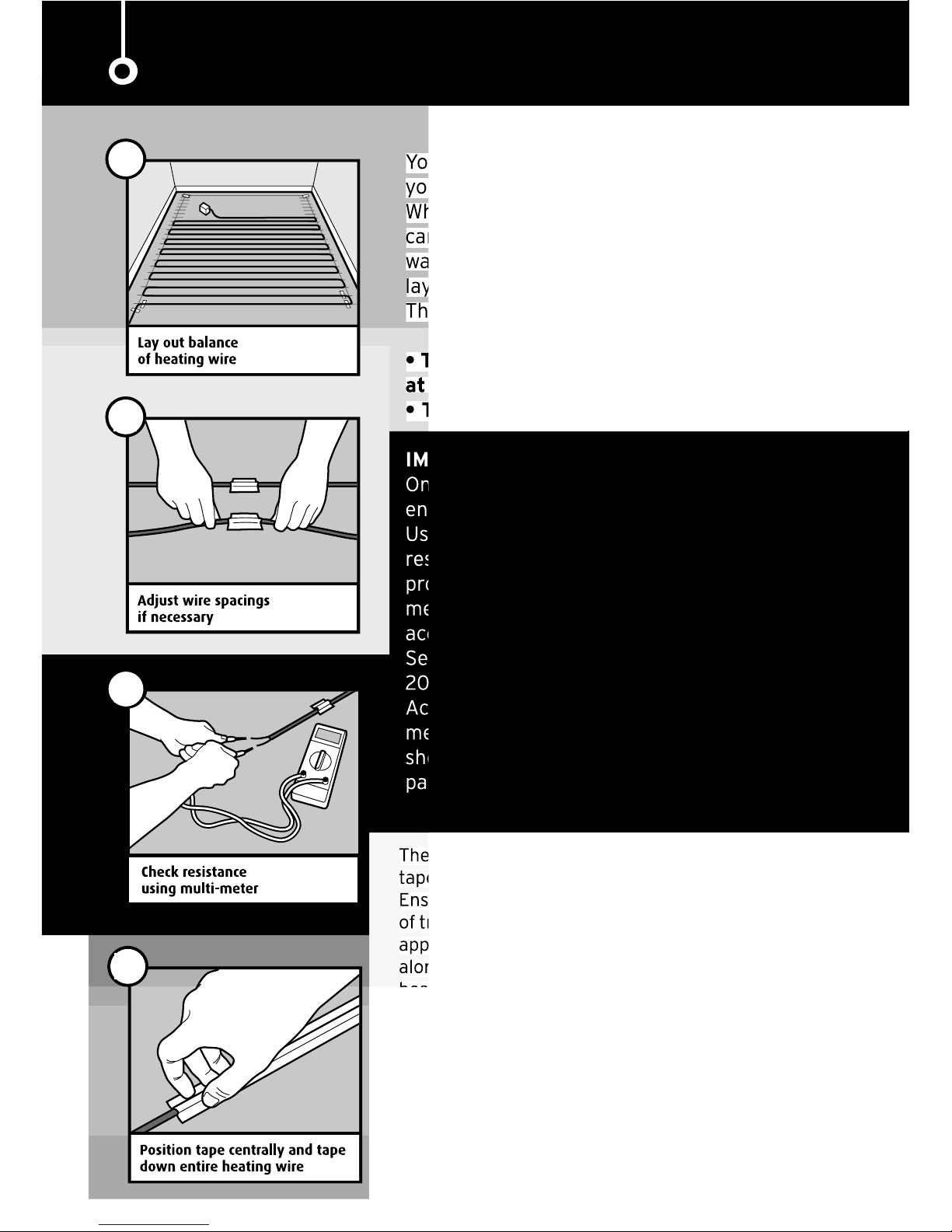
You may wish to alter the heating cable layout to fit
your particular room.
Where there are irregularities of room shape you
can adjust the layout of the heating cable to provide
warmth around the sinks, tubs, toilets, etc. (see
layout diagram page 14).
This is quite acceptable providing that:
• The heating cables are spaced at least 2” apart
at all times.
• The heating cables never cross.
IMPORTANT! – Test the Cable
Once the heating cable layout has been completed,
ensure that the cable is working properly.
Using a digital ohmmeter or multi-meter, check the
resistance of the heating cable and continuity of the
protective ground braid. Please note that analog
meters with a moving needle are not sufficiently
accurate for testing the Warmup cable .
Set your Ohm meter to measure resistance in 0 –
200 Ohms.
Acceptable readings of these ohms resistance
measurements (between the black & white wires)
should fall within +/- 15% of the values indicated on
page 6.
The entire length of the heating cable should then be
taped to the floor.
Ensure the greatest possible adhesion, with the minimum
of trapped air space beneath the taped heating cable. After
applying a length of tape, run your forefinger and thumb
along the length of the heating cable, gently squeezing the
heating cable to remove any air space between the heating
cable and the tape. As you apply the tape, gently tighten
the heating cable from the ends to ensure it is straight.
The heating cable should be located in the center of the
tape to provide maximum protection from the tiler’s
trowel. If the tape is not completely covering the heating
cable at any point, apply another layer of tape to provide
additional protection.
200 Ohms.
taped to the floor.
G
H
F
E
20
Page 21
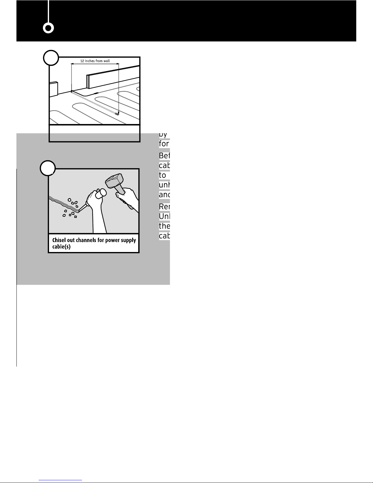
The end of the probe wire contains a capped sensor
that should be centered between two heating cables
at least 12” into the heated area. At no time should
the probe wire cross the heating cable.
Depending on the requirements of the tiler, it may
be necessary to chisel out short channels in the
subfloor to minimize the increased height presented
by the floor probe and the unheated lead provided
for connection to the thermostat or mains supply.
Before chiseling the area, ensure that the heating
cable, unheated lead and floor probe are protected
to avoid damage during chiseling. Place the
unheated lead and floor probe into the channels
and secure with fixing tape.
Remove all debris and chippings from the floor.
Unless the floor is being tiled immediately, cover
the floor with cardboard to protect the heating
cable and floor probe.
to avoid damage during chiseling. Place the
the floor with cardboard to protect the heating
Install floor probe
I
J
21
Page 22
Installation step 4
If the cable does not pass
either test, DO NOT TILE.
Call the technical helpline
on 888-927-6333
Completely disconnect
the cable prior to and
during tiling.
IMPORTANT! Test the cable
Before tiling, ensure that the cable is working properly
by using the method described on page 16.
Test b
Test the probe wire:
Temperature sensor wire must be verified before and
after installation. For probe resistances, refer to the
thermostat instructions.
Install Warmup
®
Thermostat and floor probe.
Although the Warmup
®
system is designed to be installed by any competent do it yourselfer,
only a qualified electrician should undertake the wiring and connecting of the cable to a
thermostat. This is to safeguard against the risk of personal injury and to ensure that any
installation complies with National and local codes.
Install the Warmup® Thermostat.
Instructions for the fitting of the Warmup® Thermostat can be found
inside the thermostat box.
Each cable has one unheated lead. The unheated lead
consists of one white wire (neutral), one bare copper wire
(protective ground) and one black wire (live). Please review
the information on pages 7 through 9 before proceeding.
The bare copper (protective ground) wire leading from the
unheated lead should be connected to the ground leading
from the power supply.
Floor probe location
The floor probe wire for the Warmup thermostat will be
approximately 15 feet long.
The end of the wire contains a capped sensor that should
be centered between two heating cable at least 12” into the
heated area. At no time should the probe wire cross the
heating cable.
Ensure that safety labels contained within this manual are placed by the breaker box and
near the control as described.
22
Test b
thermostat instructions.
A
the information on pages 7 through 9 before proceeding.
Install the Warmup Thermostat
and floor probe.
Page 23
Check the cable resistance with a digital multi-meter every half hour or
so. If the cable goes open circuit (no reading on the multi-meter) DO NOT
CONTINUE - call the technical helpline on 888-WARMFEET (927-6333).
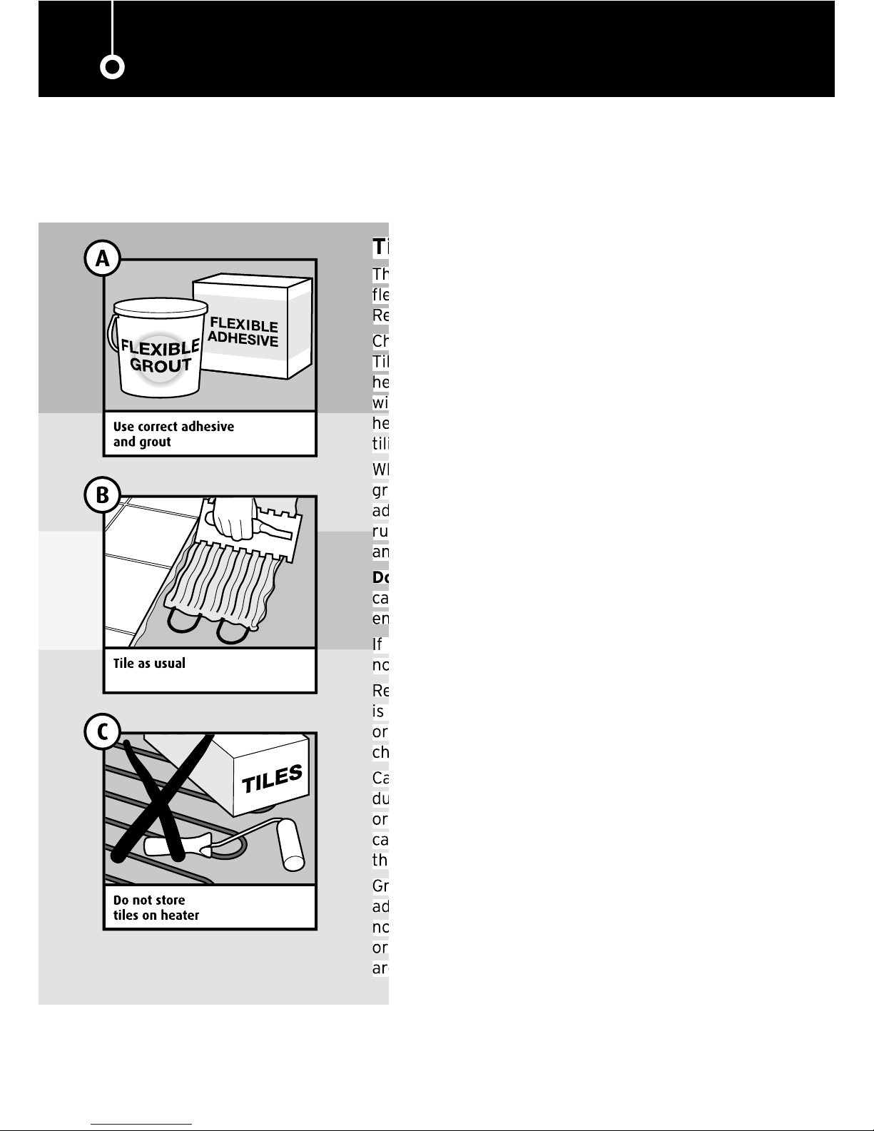
Tile and grout
The thin set mortar and grout must include an additive for
flexibility and be suitable for use with underfloor heating.
Refer to the manufacturer’s instructions for usage.
Check that the heating cable is fully taped and secure.
Tile as normal, taking care not to damage or dislodge the
heating cable with the trowel or with the tiles. If tiling
with mosaic or similar tiles, it is advisable to cover the
heating cable with latex self-leveling compound before
tiling to ensure a flat, smooth surface.
When selecting a trowel, we recommend 3/8” x 1/4” or
greater. When using a notched trowel, gently comb the
adhesive in straight lines in the same direction as the
runs of the heating cable. The trowel should be used at an
angle of approximately 45 degrees to the floor.
Do not allow the trowel to make contact with the heating
cable while applying the mortar. Use sufficient mortar to
ensure that there are no voids or hollows under the tile.
If a tile has been positioned incorrectly, take great care
not to damage the heating cable when lifting.
Remember that tiles must not be lifted once the mortar
is dry, as this will damage the heating cable. Do not store
or cut tiles on top of the heating cable. Do not allow
chippings or dust to contaminate the floor during tiling.
Care must be taken not to damage the heating cable
during the tiling process. Use a piece of carpet, cardboard
or a dustsheet as a “crawl-board” to prevent the heating
cable from being damaged by your feet or knees during
the tiling process.
Grout the floor as soon as possible as per the ceramic tile
adhesive manufacturer’s instructions. The cable should
not be made fully operational until such time as the tile
or concrete installer verifies that the cement materials
are fully cured (1-3 weeks).
Installation step 5
tiling to ensure a flat, smooth surface.
the tiling process.
Installation step 6 Fill out your warranty card.
23
Page 24
Warranty
WARMUP 30-YEAR WARRANTY
Models: USDW cables and USDW-M mats sold by Warmup, Inc.
THE WARMUP 30-YEAR WARRANTY DOES NOT EXTEND TO THERMOSTATS, WHICH ARE COVERED BY A ONE-YEAR
GUARANTEE FROM THE DATE OF ORIGINAL PURCHASE.
GOVERNING LAW. Unless otherwise governed by applicable state law, this warranty shall be interpreted and enforced
in accordance with the laws of the State of Connecticut.
This 30-Year Warranty applies:
1. Only to the original homeowner(s) from the date of purchase
2. Only if the unit is registered with Warmup within thirty (30) days after purchase. Fillin g out the card accompanying
this warranty in its entirety will complete registration. In the event of a claim, proof of purchase is required, i.e.:
invoice and receipt. Such invoice and receipt should state the exact model that was purchased; and
3. Only for the duration of the Lifetime of the floor covering under which it was originally installed if the purchaser
of the cable remains the owner of the residence in which it is installed. If the original purchaser sells such
residence, the warranty will transfer and continue for the duration of the 30 years from date of purchase.
4. Only if the cable has been grounded and protected by a GROUND FAULT CIRCUIT INTERRUPTOR (GFCI) at all
times.
COVERAGE
1. The warranty period begins on the date of purchase. Registration is effective only when a letter of confirmation
is sent by Warmup, Inc.
2. Warmup’s Undertile Cable is guaranteed by WARMUP, INC. (“Warmup”) to be free from defects in materials
and workmanship under normal use and maintenance for thirty (30) years, provided the Product is installed
in accordance with the accompanying Warmup installation manual, any special written design or installation
guidelines by Warmup, Inc. for a particular project, the National Electrical Code (NEC) and all applicable local
building and electrical codes; and
3. Provided Warmup cables are installed under ceramic tile, marble and natural stone surfaces.
4. During the period of Warranty, Warmup will arrange for the cable to be repaired or (at its discretion) have parts
replaced free of charge. The costs of repair or replacements are your only remedy under this Warranty. Such
cost does not extend to any cost other than direct cost of repair or replacement by Warmup and does not extend
to costs of relaying, replacing or repairing any floor covering or floor.
5. If Warmup, Inc. determines the repair of the product is not feasible; we will replace the product with equal or
similar features and functionality at Warmup’s sole discretion. WARMUP’S MAXIMUM LIABILITY IS LIMITED
TO THE ORIGINAL PURCHASE PRICE OF THE CABLE MULTIPLIED BY THE PERCENTAGE OF THE WARRANTY
PERIOD REMAINING.
SAFETYNET GUARANTEE GUIDELINES
1. Purchase a Warmup Undertile Heating Kit, and follow all recommended installation procedures in the Installation
Manual. Failure to follow the instructions will invalidate the guarantee.
2. If you make a mistake and cut or damage the new heating before tiling, return the damaged cable to Warmup
within 30 DAYS along with your original dated sales receipt. WARMUP WILL REPLACE ANY PRE-TILED CABLE
(MAXIMUM 1 CABLE) WITH ANOTHER CABLE OF THE SAME MAKE AND MODEL – FREE.
3. If you cut or damage the new heating during or after tiling, contact Warmup immediately for technical support.
Warmup will mail a repair kit and instructions at no charge to the installation site within 24 hours. Limit of one
free repair kit per customer or installer.
Please note :
(i) Repaired cables carry a 5 year warranty only. Under no circumstances is Warmup responsible for the repair or
replacement of any tiles which may be removed or damaged in order to affect the repair.
(ii) The Safety Net Guarantee does not cover any other type of damage, misuse, or improper installation due to
improper adhesive or subfloor conditions. Limit of one free replacement cable per customer or installer.
24
Page 25
Exclusions and Terms and Conditions
EXCLUSIONS
Warmup, Inc. shall in no event be liable for incidental or consequential damages, including but not limited to extra utility
expenses or damages to property. This Warranty is null and void if
1. The floor covering over the cable(s) is damaged, lifted, replaced, repaired or covered with subsequent layers of
flooring.
2. The cable fails due to damage caused during installation or tiling, unless damage is caused directly an employee of
Warmup. It is therefore essential to check that the cable is working (as specified in the installation manual) prior
to tiling.
3. Damage as a result of floods, fires, winds, lightning, accidents, corrosive atmosphere or other conditions beyond
the control of Warmup, Inc.
4. Use of components or accessories not compatible with Warmup cables
5. Warmup products installed outside the United States.
6. Parts not supplied or designated by Warmup, Inc.
7. Damage or repair required as a result of any improper use, maintenance, operation or servicing.
8. Failure to start due to interruption and/or inadequate electrical service
9. Any damage caused by frozen or broken water pipes in the event of equipment failure.
10. Changes in the appearance of the product that does not affect its performance.
11. The owner, or his/her designated representative, attempts to repair the product without receiving prior authorization
from Warmup. Upon notification of a repair problem, Warmup, Inc. will issue an Authorization to Proceed under the
terms of this Warranty.
If Warmup is required to inspect or repair any defects caused by any exclusions referenced above, all work will be fully
chargeable at Warmup’s inspection and repair rates then in effect.
WARMUP, INC. DISCLAIMS ANY WARRANTY NOT PROVIDED HEREIN, INCLUDED ANY IMPLIED WARRANTY OF THE
MERCHANTABLE OR IMPLIED WARRANTY OF FITNESS FOR A PARTICULAR PURPOSE. WARMUP, INC. FURTHER
DISCLAIMS ANY RESPONSIBILITY FOR SPECIAL, INDIRECT, SECONDARY, INCIDENTAL, OR CONSEQUENTIAL DAMAGES
ARISING FROM OWNERSHIP OR USE OF THIS PRODUCT, INCLUDING INCONVENIENCE OR LOSS OF USE. THERE ARE NO
WARRANTIES THAT EXTEND BEYOND THE FACE OF THIS DOCUMENT. NO AGENT OR REPRESENTATIVE OF WARMUP,
INC. HAS ANY AUTHORITY TO EXTEND OR MODIFY THIS WARRANTY UNLESS SUCH EXTENSION OR MODIFICATION IS
MADE IN WRITING BY A CORPORATE OFFICER.
DUE TO DIFFERENCES IN BUILDING AND FLOOR INSULATION, CLIMATE AND FLOOR COVERINGS, WARMUP, INC.
MAKES NO REPRESENTATION THAT THE FLOOR TEMPERATURE WILL ACHIEVE ANY PARTICULAR TEMPERATURE
OR TEMPERATURE RISE. UL STANDARD LISTING REQUIREMENTS LIMIT THE HEAT OUTPUT OF WARMUP UNDERTILE
HEATING, AS SUCH, USERS MAY OR MAY NOT BE SATISFIED WITH THE FLOOR WARMTH THAT IS PRODUCED. WARMUP
DOES WARRANT THAT ALL CABLES WILL PRODUCE THE RATED WATT OUTPUT LISTED ON THE CABLE NAMEPLATE,
WHEN OPERATED AT THE RATED VOLTAGE.
TERMS AND CONDITIONS Shipping Discrepancies:
Incoming materials should be inventoried for completeness and for possible shipping damage. Any visible damages
or shortages must be noted prior to accepting the material. Any discrepancy concerning type or quantity of material
shipped, must be brought to the attention of your Warmup® reseller within 15 days of the shipping date entered on the
packing slip for the order.
Miscellaneous:
The terms of this Limited Warranty are exclusive and supercede any other warranty or terms and conditions relating to
the subject matter whether included in a purchase order for this product or in any other document or statement.
If you need assistance or have any questions, please contact Warmup, Inc. at 888-927-6333 or visit our website at
warmup.com
25
Page 26
Complete and submit the warranty form online
at www.warmup.com!
Warmup Inc.
52 Federal Road
Unit 1F
Danbury, CT 06810
Helpline / Assistance: 1-888-927-6333
Fax: 1-888-927-4721
www.warmup.com
[email protected]
 Loading...