

Page 1
Installation Manual:
Underlaminate
Foil Heater
CHNICAL HELPLINE
0845 345 2288
IMPORTANT
R
ead this manual before attempting to
ins
tal
l y
our f
oil he
ater.
Incorrect installation could damage the
heater and will invalidate your warranty.
by filling in your Guarantee
information online at
warmup.co.uk
Complete and submit the
w
arranty form online
at www.warmup.co.uk
Page 2

2
Your Warmup® Underlaminate Foil Heater has been designed so that
installation is quick and straight forward, but with all electrical systems,
certain procedures must be strictly followed.
Please check the sizing guide at the back of this manual to ensure that
y
ou ha
ve the correct heater(s) for the area you wish to heat.
Getting Started
Before installing your new Warmup®underlaminate foil heating mats, be sure you have the following
additional parts:
Electrical junction box – used as the connecting junction for the electrical supply cables of the
heating mats.
Control thermostat – allows you to control the temperature of the room.
Residual Current Device - Consult your electrician regarding the applicable RCD.
Hard insulation materials – used as heat insulator under the foil heating mats in installations with
concrete subfloors to provide more efficient heating. The material comes in plates, usually made from
foamed Polyurethane or Polystyrene and should have Compressive strength of more than 28PSI
(2Kg/cm
2
). An example of this is the Warmup®Insulation Board.
Soft insulation material – any soft insulation suitable for wood or laminate. which has a fire rating
of B2 or greater.
Page 3

2
4
6
7
9
13
16
Getting Started
Important!
About the Product/
Modifying Your Heating Mats
Step 1:
Planning Your Installation
Step 2:
Laying Out Your Foil Heating Mats
Step 3:
Making the Electrical Connections
Installation Examples
Standard sizes of foil heating
mats and their values
Contents
NOTICE:
This product MUST be used
with a dedicated RCD
(residual current device)
If these instructions are followed you should have no problems.
However, if you do require help at any stage, please call our 24hr helpline:
Warmup Technical Helpline 0845 345 2288
You can also find a copy of this manual, wiring instructions, a list of frequently asked
que
s
tions and mor
e help
ful information on our website:
www.warmup.co.uk
3
Page 4

Important!
WARNING
Onc
e the f
oil heating mat has been installed avoid all traffic over the mat until the floor has been laid.
Do no
t ins
tal
l the f
oil he
a
ting mat until the floor is ready to be laid. If the floor is not being laid
immediately, all heating mats must be protected with two layers of cardboard or hardboard to
prevent damage.
Immedia
tely prior to the floor being laid, check it has not been damaged in transit.
If y
ou are in any doubt call the Warmup helpline on
0845 345 2288
4
Please read carefully before installing your Warmup®underlaminate foil
heating mats.
DON’T leave insulating materials such as bean bags; linen or towels on the floor
surface. The maximum thermal resistance recommended between the heater
and the room is 0.15 m2K/W (1.5 TOG).
DON’T overlap heating mats.
DON’T fold or wrinkle Warmup®Underlaminate foil heating mats.
DON’T place heavy/sharp tools (or any other potentially damaging object)
on top of the heating mats.
DON’T walk unnecessarily on the foil heating mats.
DON’T install electrical cables or pipes under the floor with the foil heating mats.
DON’T use cellulose insulation.
DON’T install mats when the room temperature is below -5ºC.
DON’T install foil heating mats anywhere except inside buildings.
DON’T install foil mats under walls or partitions,or in areas under heavy cabinets,
closets, or fixtures (toilets, sinks, tubs, etc.).
DON’T install foil mats within 30mm of any heat conductive building part, such as
cold water pipes.
DON’T install foil mats within 10mm of one another, 50mm of any wall, or
150mm of a fireplace or hot water pipe.
DON’T connect any other electrical appliance on the same electric fused
spur or RCD/SPUR unit of the heating system
DON’T install foil heating mats under wooden floor, if the wooden floor is thicker than
18 mm.
DON’T put accustic material between the foil heating mats and the wooden floor,
installing wooden type floor.
DON’T use this heater under any floor covering other than wood or laminate
flooring.
DON’T place items on the floor surface which will stop the air flow or not allow heat
to rise into the room.
DON’T:
Page 5

Important!
5
ALWAYS ensure all earth leads are connected to the earth ring.
ALWAYS ensure that the electric circuit that supplies electricity to the Warmup
®
Underlaminate heating system is equipped with a 30mA residual current
device (RCD).
ALWAYS connect all cold wire leads from the Warmup®Underlaminate foil heating
mats in parallel inside an electrical junction box or boxes.
ALWAYS ensure that the total current needed for all mats connected in parallel
is not more than 80% of the listed amperage capacity of the electrical
junction box and its power supply line and breaker (For advice consult
your recommended Part P qualified electrician).
ALWAYS provide each room with an Warmup®Underlaminate foil heating system with
its own electrical junction box and control thermostat. Each Warmup®thermostat
has a maximum capacity of 16 Amps. If the amount of Amps in the room is
greater than 16 Amps, divide the amperage over several thermostats.
(To calculate the amount of Amps in the room see tables in page 16).
ALWAYS use insulation under the mats to reduce running costs and warm-up
time. Check with your installer to determine the R value of the sub floor
insulation layer. If there is no insulation, or if the R value of the insulation
layer is lower than 0.57ft2*h*°F/Btu (0.1m2*°C/W or 1 Tog), please read
the insulation instructions on page 6 and act accordingly.
ALWAYS ensure that no sharp edges (e.g. metal-edged laminate locking systems)
come in contact with the foil heating.
ALWAYS fit the floor sensor and ensure that the thermostat is set for the correct
heater type and floor finish.
ALWAYS:
Note: Timber products often have a limitation on the maximum temperature allowed for floor heating- This
is usual
ly ar
ound 27
ºC. Check with your flooring supplier what the limitations are for your preferred floor
finish.
As with all electrical projects which are subject to Part P Building Regulations, all electrical work should be
carried out by a certified/qualified electrician.
All work must conform to BS 7671:2008 and the current IEE Wiring Regulations.
Page 6
About the Product
Specifications:
Construction: Aluminium foil heater with fluoropolymer insulated twin-conductor,
sandwiched between 2 layers of specially reinforced aluminium
foil.
Standard Wattage: 80 W/SqM and 140 W/SqM
(see page 16 for individual mat specifications)
Mat Width: 500mm
Heating cable spacing: 50mm
Cold lead length: 3m
6
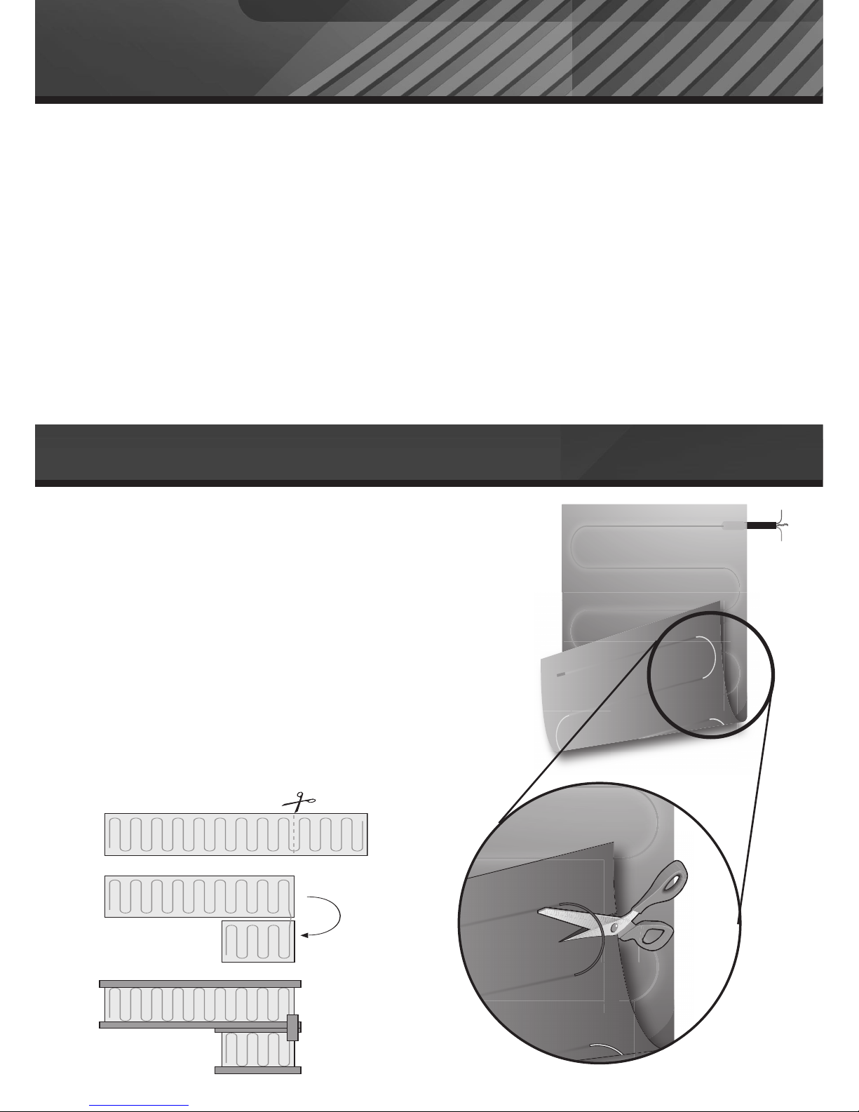
CCuuttttiinngg aanndd ttuurrnniinngg tthhee mmaatt::
In some instances, you may need to cut
and turn the mat to suit the room.
IItt iiss eesssseennttiiaall tthhaatt yyoouu ddoo nnoott ccuutt,, ttwwiisstt oor
r
kkiinnkk tthhee hheeaattiinngg wwiirree.
.
To make a cut, turn the mat over so that
the loops are exposed. Lift the wire out of
the way when cutting. Once the aluminium
foil has been cut and the mat has been
repositioned, use the aluminium tape
provided to cover the exposed wire and link
the two pieces of the mat.
Modifying Your Heating Mats
Top
Cold
Lead
Exposed
Wire
Aluminium Mat
Bottom
Page 7
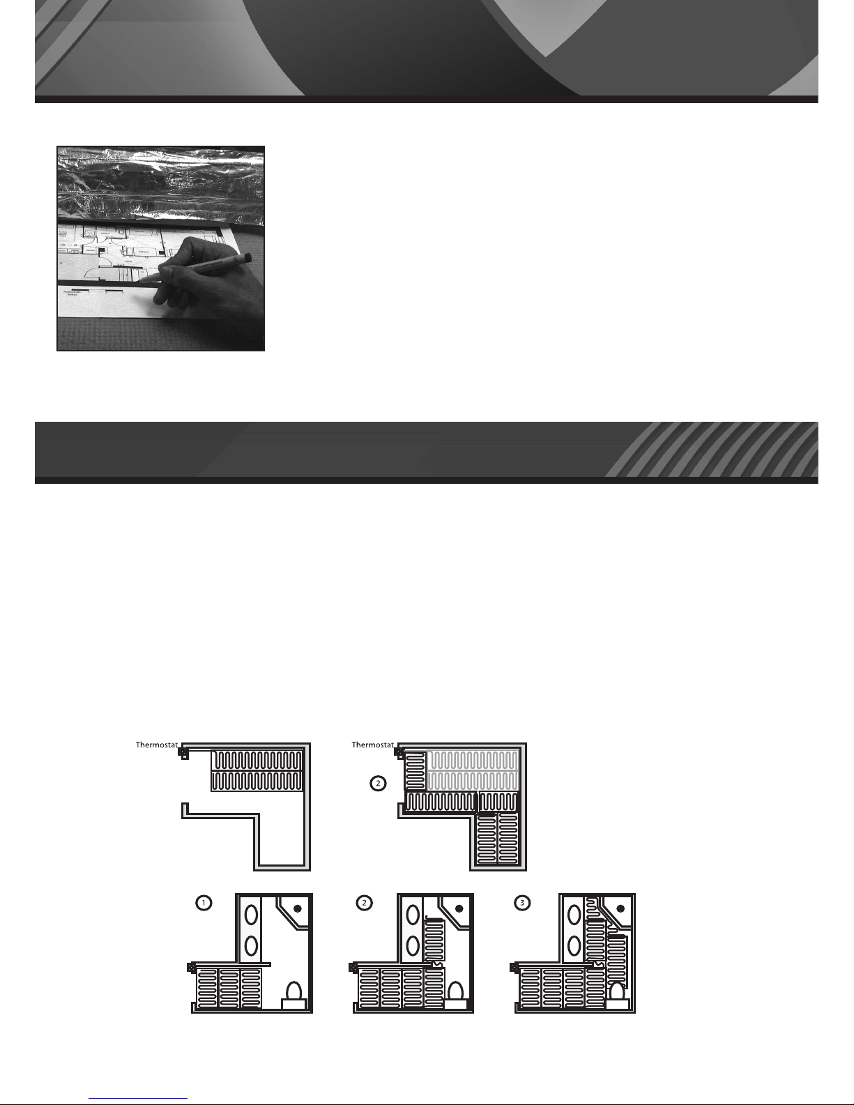
Before installing, draw an installation plan showing the placement of the
mats, floor sensor, and junction box
or boxes.
The Warmup
®
underlaminate foil heating mats should cover at least 80% of
the floor area of your room to be used as a primary heat source*. Warmup’s
foil heating mats are available in several convenient sizes. Choose the
combination of heating mats that best enables you to cover the
recommended 80% of your room. Plan to use the larger foil heating mats as
much as possible and to use smaller mats only as gap fillers.
Note: The mats are supplied with 3 metres of electrical cold leads.If
this is not enough, ask your electrician to extend the electrical
supply cables.
*Depending on insulation, air-flow & overall heat-loss within the room, additional heating may be required.
1 Clean all debris from the floor base.
2 Insert Warmup® Insulation Board
3 Clean all debris from the surface of the grout or insulating material.
4 Roll out heating mats on top of the insulating material. It is recommended to leave a gap of about
50mm from the wall to the heating mats, and a gap of about 10mm between each mat. Ensure that
each heating mat is completely flat. Make sure that the cold leads of the mats are on the side of the
mat that is closest to the location of the electrical junction box (See step 3 – Making the Electrical
Connection).
Step 2: Laying Out Your Heating Mats
Step 1: Planning Your Installation
7
NOTE:
When laying two or
more heaters, ensure
the cold tails reach the
thermostat.
Page 8
Step 2: Laying Out Your Heating Mats
8
5 Your mats come with aluminium tape. Stretch the mats
and secure the mats to the floor with the tape. Where
required, additional duct tape can be used.
IIff aannyy wwiirree hhaass bbeeeenn ddeettaacchheedd ffrroomm tthhee ffooiill mmaatt ((wwhheen
n
mmaatt iiss ccuutt aanndd ttuurrnneedd)),, tthhaatt wwiirree MMUUSSTT bbee ccoovveerreedd bbyy
aalluummiinniiuumm ttaappee,, aanndd bbrriiddggee tthhee ggaapp bbeettwweeeenn tthhee
sseeccttiioonnss ooff mmaatt..
This is necessary in order to keep the ground circuit
intact.
6 Place the electrical supply cables of the mats between
the mats toward the junction box. Place the electrical
supply cables so that they do not cross each other.
Important!
Ensure that the electrical supply cables of the mats
do no
t cr
os
s o
v
er the mats.
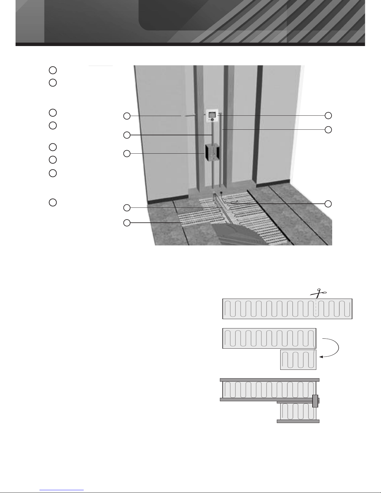
1
2
3
5
4
6
7
8
Power Supply
Electrical wire
installed in an
electric conduit
Junction box
Electrical supply
cables
Foil heating mat
Thermostat
Floor sensor
installed in an
electric conduit
Floor sensor installed
in floor (equal
distance between
heating foils)
1
2
3
4
5
6
7
8
Page 9
Step 2: Laying Out Your Heating Mats
9
7
Since the joint is slightly thicker than
the rest of the mat, create a slight groove in the insulation
board under the joint to ensure that the heating
mat lays flat. Create a groove for the cold leads
at the point at which they cross.
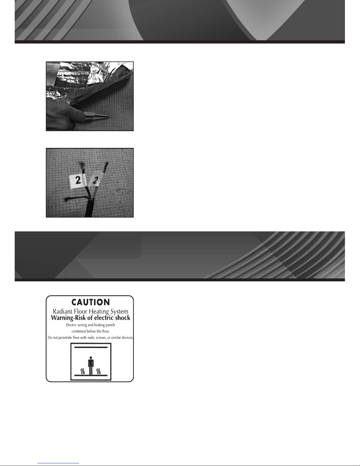
8 Mark each pair of cold leads coming from the same
mat with a number. Place a small sticker with the number
of each pair of leads close to the end of the lead.
Note: All electrical connections must be performed
by a fully qualified and Part P certified electrician.
Important! Tightly screw all connections to ensure
good electrical contacts.
1
Install the electrical junction box or boxes above floor
level according to local safety and building regulations
and codes. Place the following label (attached to back
cover) on the electrical junction box or boxes indicating
that an underfloor heating system is installed in the
room.
2 Install the control thermostat as far as possible from
any heat sources or heat sinks such as fireplaces,
dir
ect sunlight
, windo
ws
, doors, or anything that
could possibly affect proper temperature readings.
The sugge
sted placement is 1.6m above floor level.
Step 3: Making the Electrical Connections
Page 10
Step 3: Making the Electrical Connections
10
3
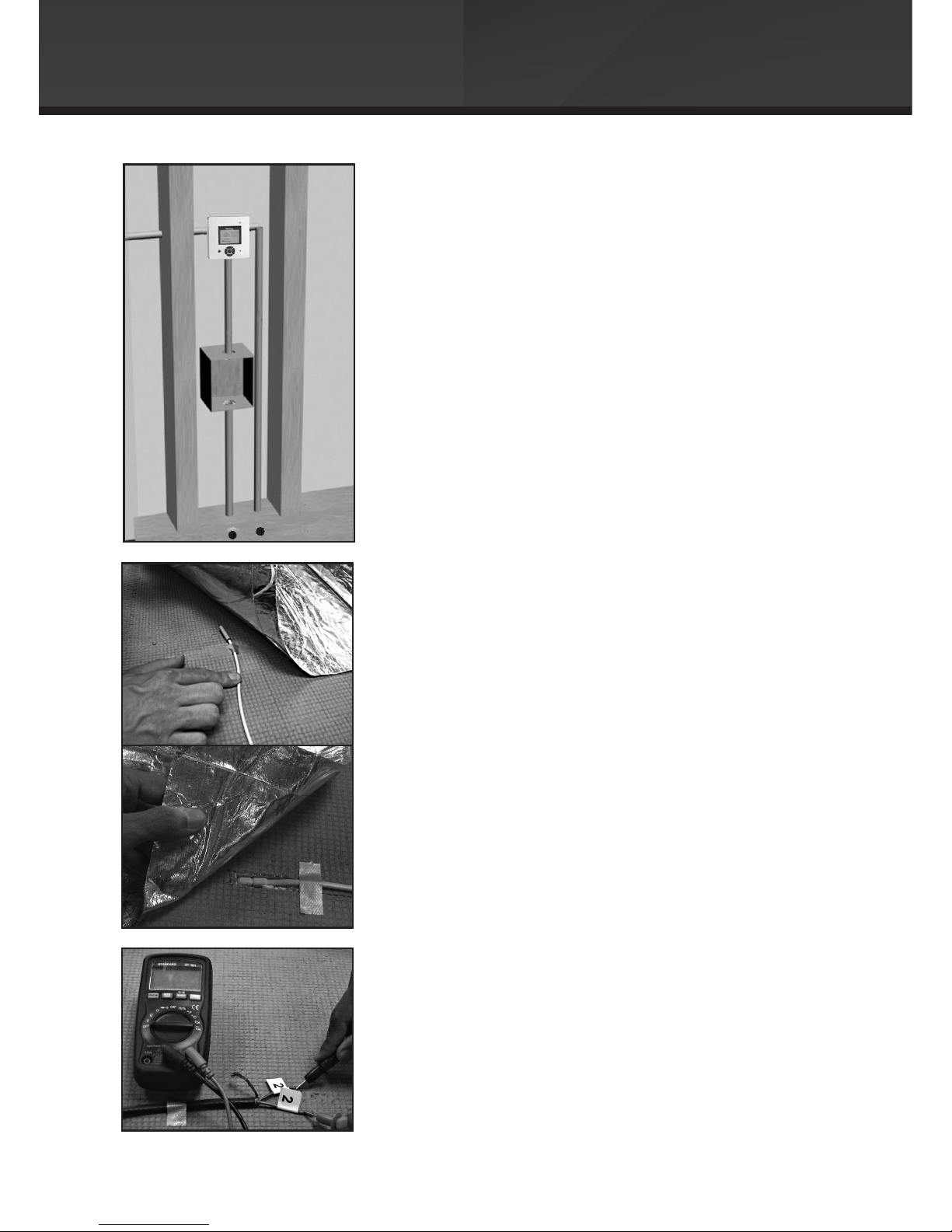
Install an electric conduit to the junction box and
thermostat as in the following diagram.
4 Connect the floor temperature safety sensor to the
thermostat through a conduit, and install between two
heating wire runs on the mat, at least 500mm from the
wall.
Note: Make sure that the sensor is placed
between two runs of wire, at the opposite end
from the heating wire loop.
The probe wire must not touch or be crossed by
the heating element.
5
Measure the resistance of the heating system and
record the value. Verify that the values you measure
are in line with the resistance value that is printed
on the specific ma
t namepla
t
e
.
Page 11
Step 3: Making the Electrical Connections
11
6
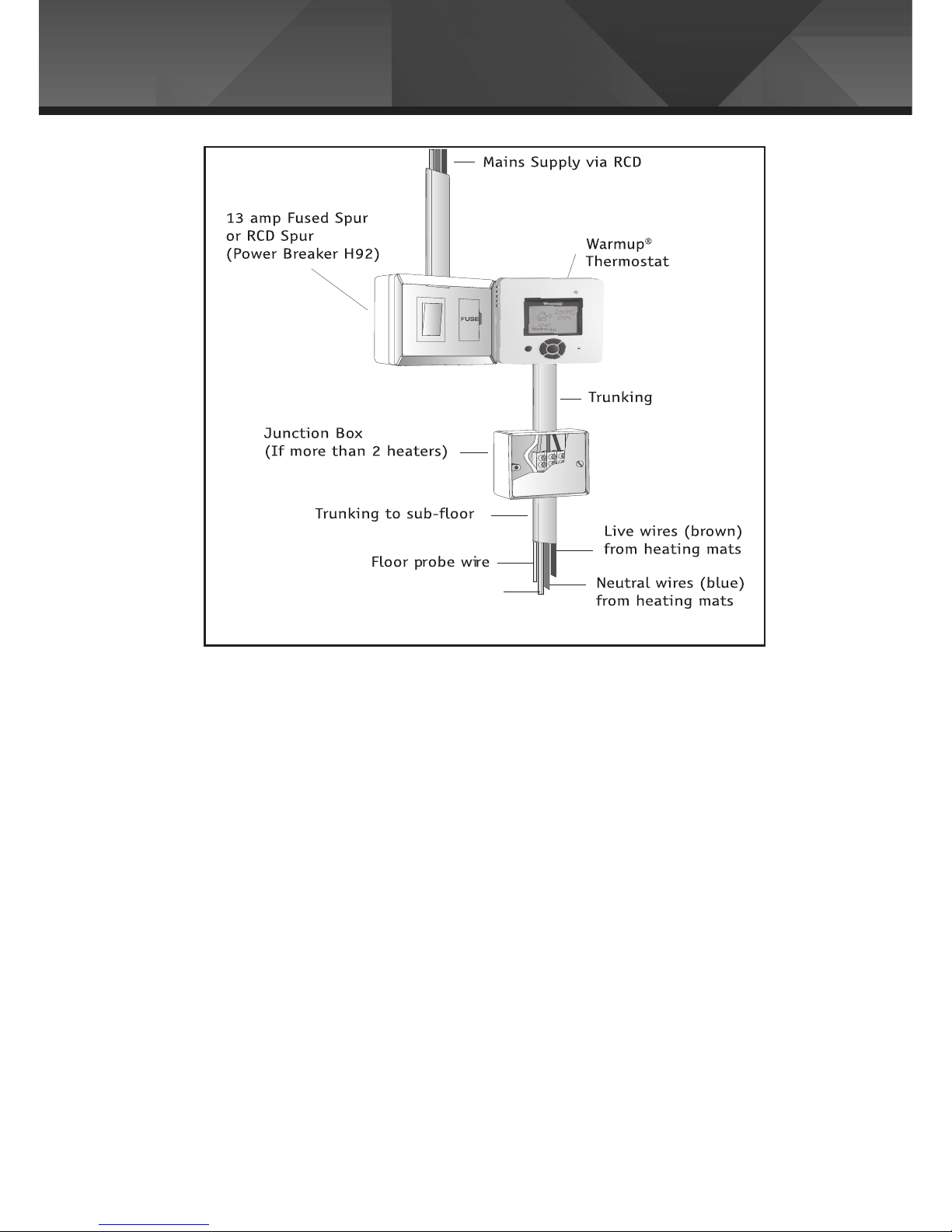
All earth connections from the heaters must be connected to the earth from the power
supply of the house.
7 In parallel, feed each mat to the electrical junction box. Make sure that you can see
the sticker with the numbers of the leads. If necessary, shorten the leads, but make sure
the sticker with the leads' numbers are affixed to the shortened lead.
8 Expose the conductor in each lead.
9 Connect all leads of the same colour.
10 Insert each coloured lead to one connector in the junction box.
11 Connect the same colour cold lead between the thermostat and the connector
in the junction box.
WARNING:
This product MUST be used with a dedicated
30MA RCD (residual current device).
The RCD should be tested regularly in accordance
with the manufacturer's guidelines.
Page 12
Earth wires (green/yellow)
from heating mats
Step 3: Making the Electrical Connections
12
12
Connect the wires to the control thermostat according to the wiring instructions found in
the thermostat box.
13 Switch on the foil heating system (see the directions in your thermostat manual)for half
an hour to ensure that the system is working properly.It is important to check each entire
system to ensure each foil mat is heating.
14 Switch off the heating system (see the directions in your thermostat manual).
15 When the mats are cool,lay down your floor covering.
Page 13
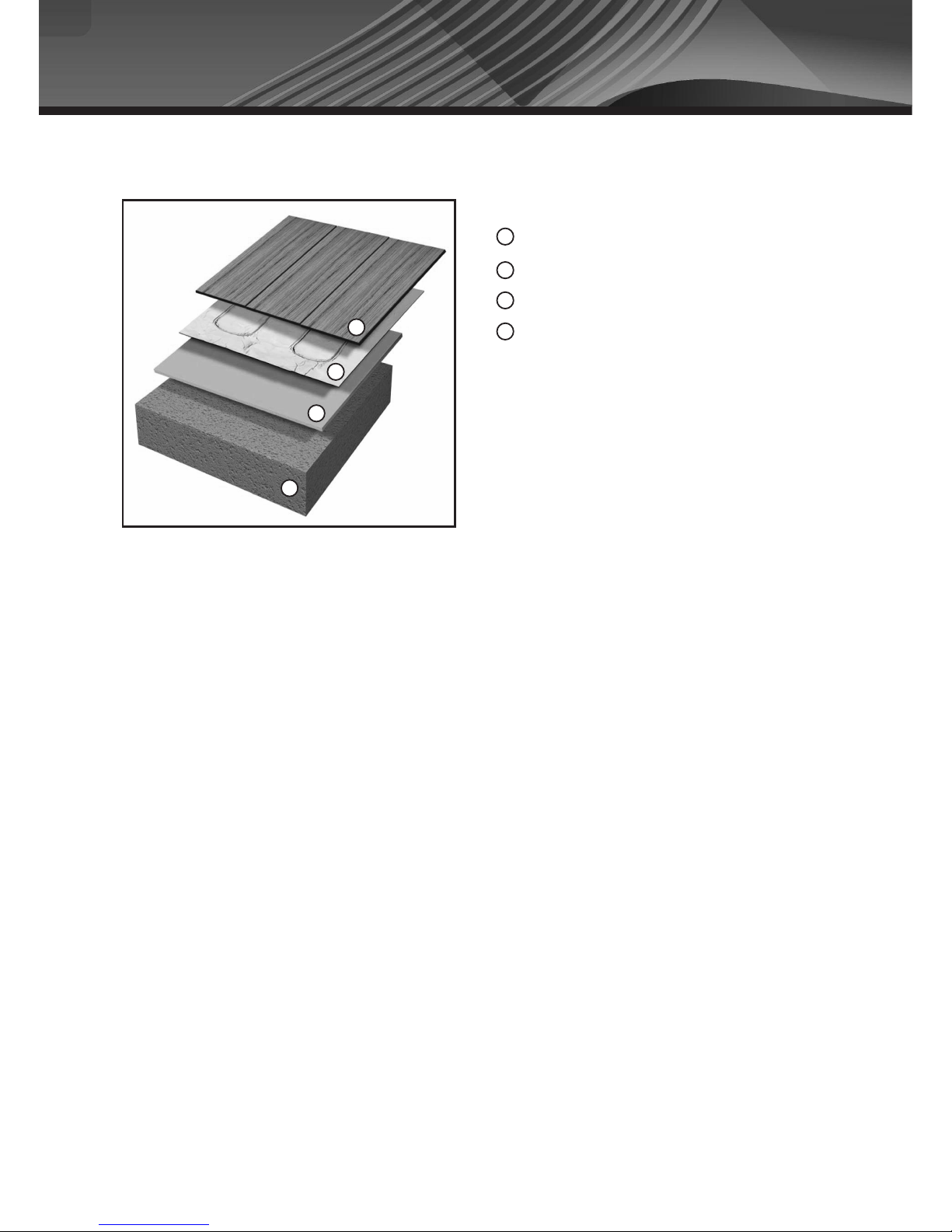
Installation Examples
Wood flooring material
Heating mat
Insulation material
Floor slab (wood or concrete)
2
3
4
1
2
1
3
4
13
Under wood or laminate flooring
Hard insulation materials – used as heat insulator under the foil heating mats in
installations with concrete subfloors to provide more efficient heating. The material comes in
plates, usually made from foamed Polyurethane or Polystyrene and should have
Compressive strength of more than 28PSI (2Kg/cm
2
). An example of this is the Warmup
®
Insulation Board.
Soft insulation material – any soft insulation suitable for wood or laminate. which has a
fire rating of B2 or greater.
Page 14
NOTES:
14
Page 15
If the heater fails due to damage caused during installation, this
guarantee does not apply. It is therefore important to check that
the heater is working (as specied in the installation manual)
prior to laying the oor covering.
Underlaminate Heater, and follow all
2. If you make a mistake and damage the new heater before laying the
oor covering, return the damaged heater, to Warmup within 30 DAYS
along with your original dated sales receipt. WARMUP WILL REPLACE
ANY HEATER (MAXIMUM 1 HEATER) WITH ANOTHER HEATER OF THE
SAME MAKE AND MODEL-FREE.
3. If you damage the new heater during installation of the oor covering,
contact Warmup immediately to arrange for a site visit. You will need to
show our engineer your original dated sales receipt.
ooring which
(iii) Damage to the heater that occurs after laying the oor covering is
not covered by the SafetyNet™ Installation Guarantee.
15
Ver. 0809
Page 16
16
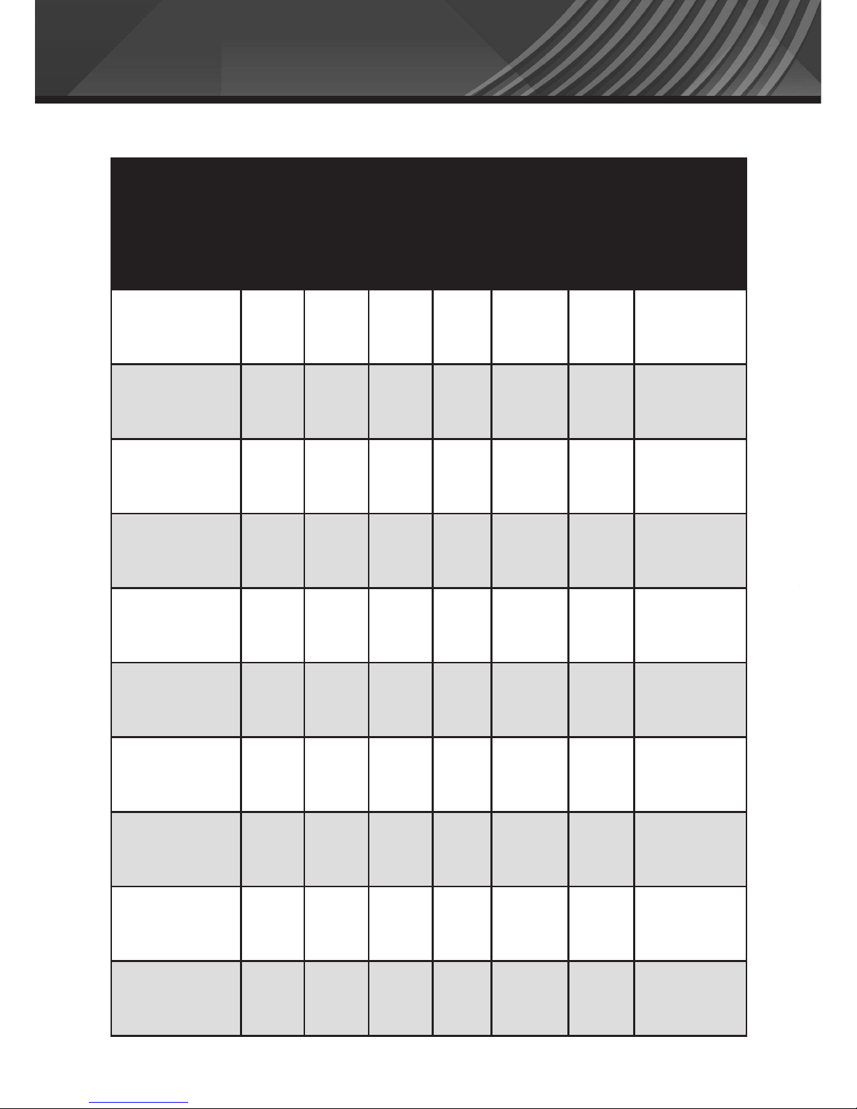
Standard sizes of foil heating mats and their values
220-240 Volts: Models 80 and 140 watts per m
2
Model
Area
SQM
Length
(m)
Width
(m)
Total
Watts
Watts /
SQM
Amps
Total
Resistance
WLFH-140W/210 1.5 3 0.5 210 140 0.91 251.90
WLFH-140W/280 2 4 0.5 280 140 1.22 188.93
WLFH-140W/420 3 6 0.5 420 140 1.83 125.95
WLFH-140W/560 4 8 0.5 560 140 2.43 94.46
WLFH-140W/700 5 10 0.5 700 140 3.04 75.57
WLFH-140W/840 6 12 0.5 840 140 3.65 62.98
WLFH-140W/980 7 14 0.5 980 140 4.26 53.98
WLFH-140W/1120 8 16 0.5 1120 140 4.87 47.23
WLFH-140W/1260 9 18 0.5 1260 140 5.48 41.98
WLFH-140W/1400 10 20 0.5 1400 140 6.09 37.79
Page 17
Page 18
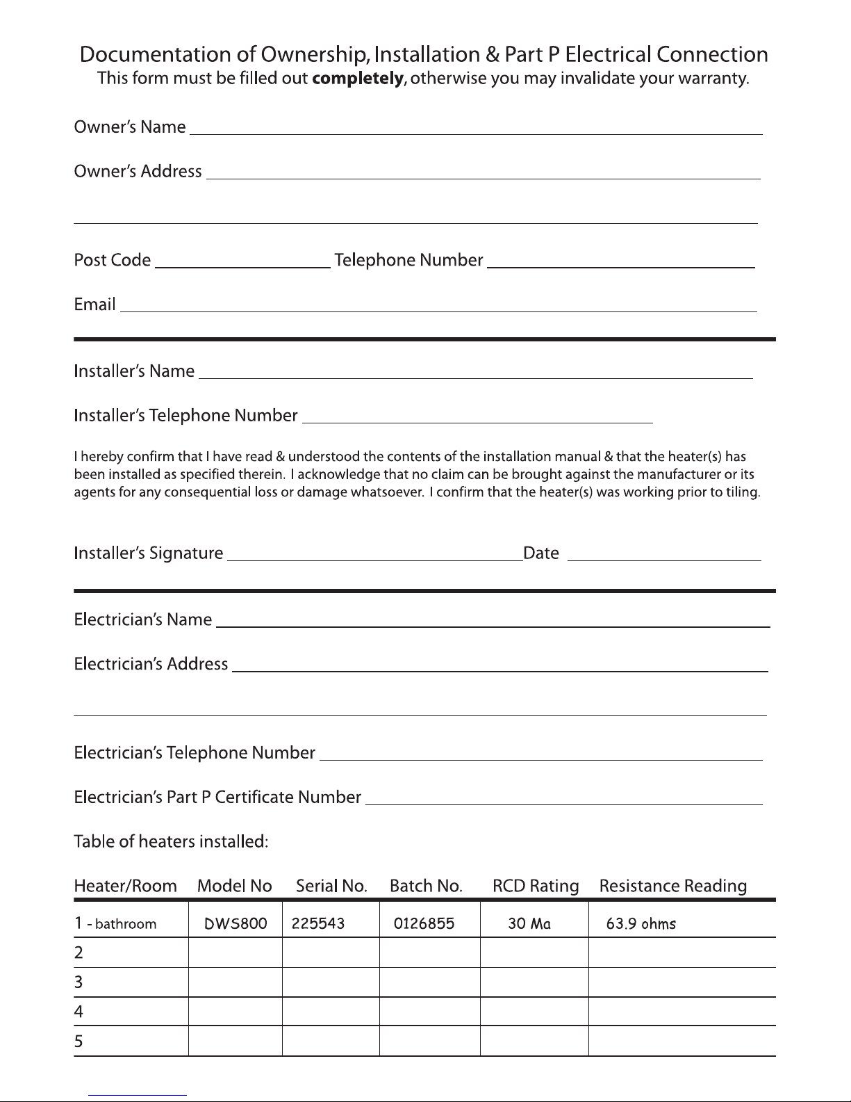
Name
Address
Post code Telephone number
E-mail
Installer name
Date of purchase
Please state which room the heater(s) is installed:
I hereby confirm that I have read and understand the contents of the Installation Manual, and that the heater has been installed as specified therein.
I acknowledge that no claim can be brought against the manufacturer or its agents for any consequential loss or damage whatsoever.
I confirm that the heater was working prior to the commencement of tiling.
Signed Date
other
Kitchen
Bathroom
Conservatory
Hall
Fill in your registration online at www.warmup.co.uk to receive your FREE GIFT.
Page 19
Page 20
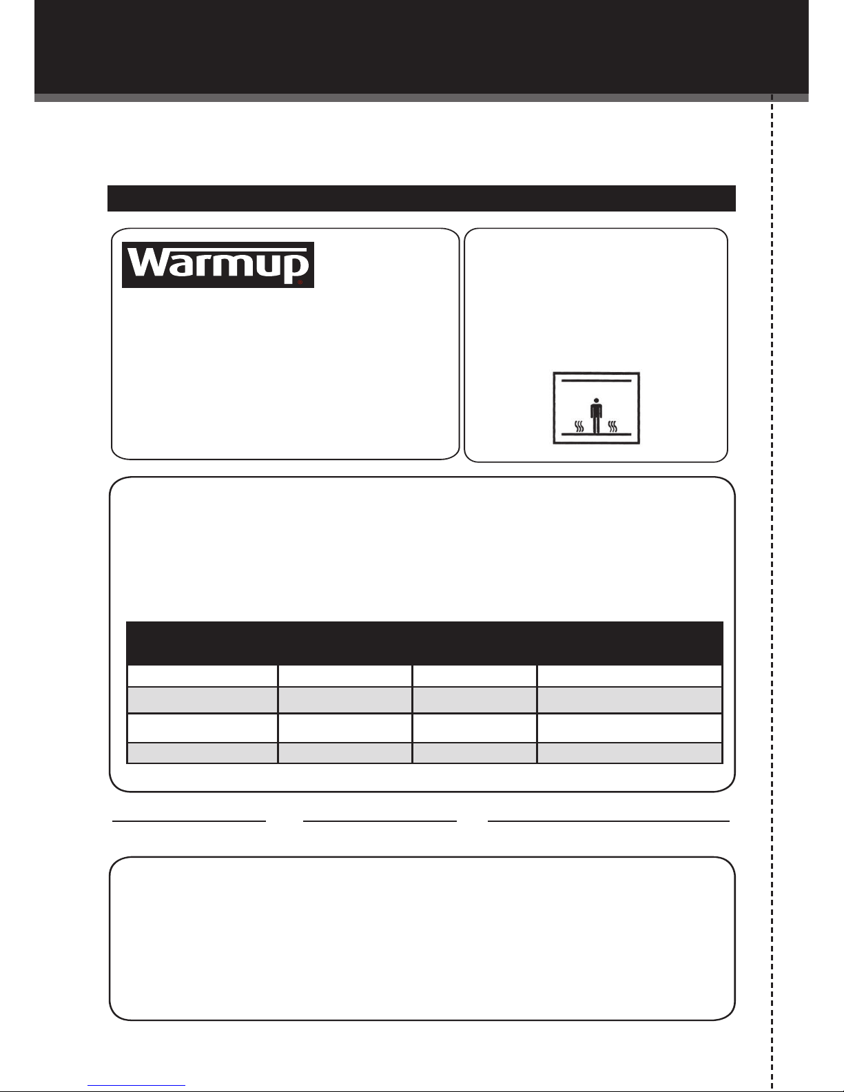
NNootteess
Heater Location _________________________
Total Wattage __________________________
Place this card in a visible spot close to the consumer unit.
SignedDate
Company stamp/name
CAUTION
CAUTION
Radiant Floor Heating SystemsRadiant Floor Heating Systems
Warming-Risk of electric shockWarming-Risk of electric shock
Electric-wiring and heating panels
contained below the fl oor. Do not
penetrate with nails, screws, or similar
devices. Do not restrict the thermal
emission of the heated fl oor.emission of the heated fl oor.
Attention:
Do not cut or shorten the heating element wire.
Ensure that the entire heating elements including the joints are installed under the
fi nished fl oor.
The Heating element must be used in conjunction with a 30mA RCD.
Heater Model Resistance Before Resistance After Insulation Resistance
This form must be completed as part of the Warmup Guarantee. Ensure that
the values are as per the instruction manual.
This card must be situated close to the consumer unit in a visible place.
Note: Draw a Plan showing the layout of the heater.
Warmup Plc 702 Tudor Estate Abbey Road London NW10 7UW T: 0845 345 2288 F: 0845 345 2299 www.warmup.co.uk
Page 21

The WARMUP word and associated logos are trade marks. © Warmup Plc. 2009 - Regd. TM Nos. 1257724, 4409934, 4409926, 5265707. E & OE.
702 Tudor Estate
Abbey Road
London
NW10 7UW
Web: www.warmup.co.uk
Email: [email protected]
Tel: 0845 345 2288
Fax: 0845 345 2299
V0310
 Loading...