

Warmup TSTAT, PB130-230 Owner's Manual
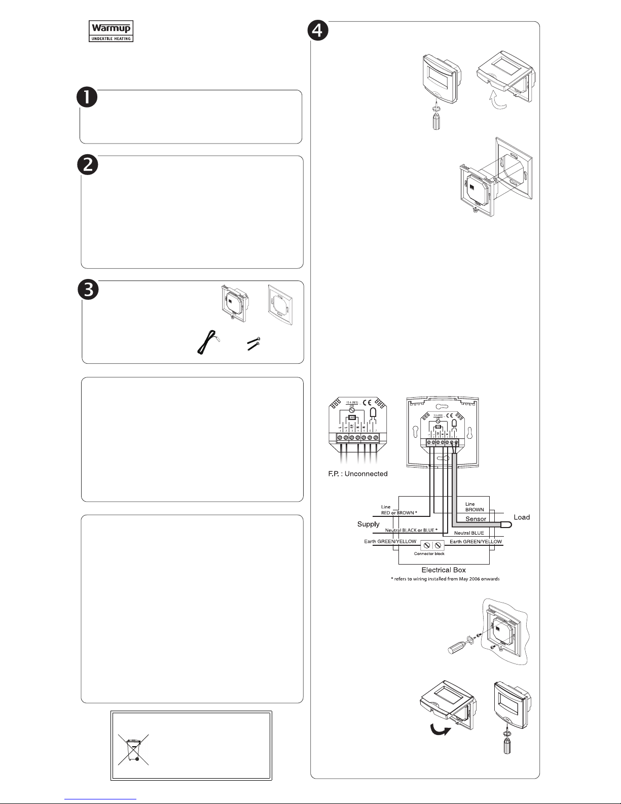
n Remove the screw
holding the control
module to the
power base.
The screw cannot be
completely removed.
o If you have a wall plate:
Before making the connections,
make sure that the base covers the
electrical box entirely. Otherwise,
install the cover plate behind the
base.
NOTE: The cover plate can also be used
to cover the plate for aesthetic reason.
p Connect the wires:
• Power: Terminals 1 and 5
• Load: Terminals 2 and 4
• Floor sensor: Terminals 6 and 7 (no polarity)
• Terminal 3 (F.P.) is not connected
NOTE: The terminals are designed to handle wires between 0.33
and 4 mm
2
.
The floor sensor must be centered between the heater wires
(80°C max.). Do not place the floor sensor next to a heater wire.
The temperature sensor wire must not cross any heater wires.
Make sure the temperature sensor wire is properly affixed along the
wall, in the concrete and into the electrical box (insulated material
only and could be run in a raceway) and that there is no interference
with the thermostat.
r Push the wires into the electri-
cal box and secure the base to
the electrical box anchorage
using the screws provided.
s Install the control module
onto the power base
(see owner’s guide).
t Return power to the heating system.
Material
n One (1) PB130-230 power base
o One (1) wall plate
p One (1) floor sensor
q Two (2) screws
PB130-230
Power Base
Installation Instructions
Technical Specifications
Supply: 230 VAC, 50 Hz
Maximum load: 3450 Watts (NI) @ 230 VAC; 15 A (resistive only)
Compliance: EN60730-2-9 / EN50081-1 / EN50082-2
Storage: -20°C to 50°C (-4°F to 122°F)
Protection: Class 2
Protection degree:IP20
Automatic action: Type 1.B
Environment: Normally polluted
Size (H•W•D): 2.94 x 2.94 x 0.53 in. (74.6 x 74.6 x 13.3 mm)
Warranty
WARMUP PLC THREE-YEAR LIMITED WARRANTY
This product is warranted against material defects and workmanship in
normal use for a period of three (3) years, from the date of the original
purchase from authorized dealers. During this period,Warmup plc will
repair or replace the product with a new or of equivalent quality at Warmup
plc’s option, without charge, any product proven defective in normal use.
Warranty does not cover transportation costs. Nor does it cover a product
subjected to misuse or accidental damage. This warranty does not cover
the cost of installation, removal or reinstallation.
This limited warranty is in lieu of all other warranties, obligations or
liabilities expressed or implied by the company. In no event shall Warmup
plc be liable for consequential or incidental damages resulting from
installation of this product. This warranty does not affect your statutory
rights.
The defective product and the original sale receipt must be returned to the
original dealer or shipped pre-paid, insured and addressed to:
Warmup PL C
702 Tudor Estate
Abbey Road
London NW10 7UW
WEEE Directive:
• Do not dispose along with
normal household waste.
• Do not burn.
The product and its packaging must be
disposed at a suitable recycling centre.
Introduction
The PB130-230 power base is designed to power a TSTAT control
module. The resistive load must not exceed 3450 watts (NI) @
230 VAC (15 A).
Installation Guidelines
TURN OFF POWER TO THE HEATING SYSTEM AT THE MAIN
POWER PANEL TO AVOID ELECTRICAL SHOCK.
Installation must be carried out by an electrician.
All work must conform to the most recent IEE regulations for
electrical installations and wiring.
This thermostat must be connected on a circuit equipped with
an RCD. It must be installed on a certified electrical box.
The thermostat must be installed on an inside wall.
1/3 400-608-000-C
Installation and Wiring
Introduction
Your new programmable electronic thermostat is
designed to control electric floor heating systems and is
equipped with a microprocessor and proportional integral
adaptive (PIA) temperature control technology for total
comfort.
The TSTAT is also preprogrammed to fit most
homeowners’ lifestyles and settings can be easily
modified if required.
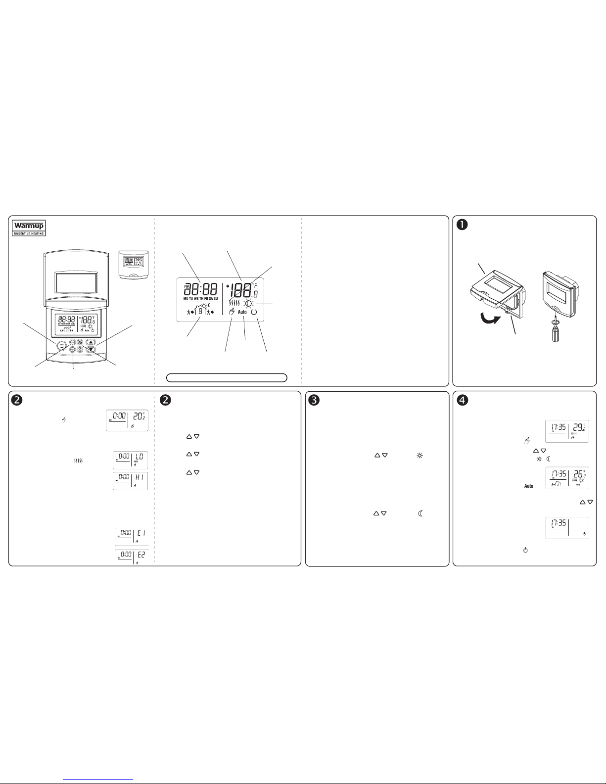
On/Standby Feature
The thermostat has an On/Standby feature making it
possible to put the thermostat in sleep mode when its use
is not required (e.g. summer).
Display with Backlight
The convenient backlight will light at the press of any
button and will stay on for 12 seconds.
Align the bracket tabs on the control module with the
holes located on top of the power base.
Note: Keep the thermostat's air vents clean and free from
obstructions.
Note: The screw cannot be removed completely.
Install the Control Module
Power base
Control module
On the first installation, the screen
displays: 0:00, MO, and the floor
temperature.
Temperature reading is above or below display
limits:
LO: The temperature is below -10°C.
The heating indicator is
displayed and the relay is closed
(energized). The screen will display
the floor temperature when it rises
above -10°C.
HI: The floor temperature is above 60°C. The floor
temperature will be displayed when it drops below
60°C.
The floor sensor is defective:
E1: The floor sensor is not connected
properly or is open circuit.
E2: The floor sensor is short circuited.
If this situation occurs, you can configure
the thermostat to operate like a regulator.
See “Advanced Programming” for more information.
Follow these steps to set the current time and day:
n Press CLK; the hour segment flashes.
o Press to set the hour.
p Press CLK; the minutes segment flashes.
q Press to set the minutes.
r Press CLK; the day flashes.
s Press to set the day.
t Press MODE to exit.
Note: To switch from 12-hour to 24-hour, see “Advanced
Programming” .
Note: After 60 seconds of inactivity, the thermostat will
automatically exit programming mode.
Comfort (default is 28°C)
Represents the temperature you wish to have when you
are at home (morning and evening).
Associated with programs 1 and 3
To modify:
Set the temperature using and press until the
icon is displayed on the screen (approx. 3 seconds).
Economy (default is 20°C)
Represents the temperature you wish to have when you
are away at work and during the night.
Associated with programs 2 and 4
To modify:
Set the temperature using and press until the
icon is displayed on the screen (approx. 3 seconds).
There are three operating modes:
Manual
Maintains a constant temperature.
Press MODE to select .
Set the temperature using or press one of the
pre-defined setpoint buttons .
Automatic
Executes the schedule.
Press MODE to select .
To bypass the current program for
a 2-hour period, simply define a new setpoint using .
The Auto icon flashes to indicate the bypass.
Standby
This mode is used to put the
thermostat in sleep mode when it
is not required (e.g. summer).
Press MODE to select .
First Power On Clock and Day Settings Setpoints Definition Select the Operating Mode
2/3 400-608-000-C
Current
program when
Auto mode is
activated
Floor temperature.
(arrow indicates a
setpoint
adjustment/view)
Heating
indicator is
displayed
when heating
is ON.
Manual
Mode
Comfort
and
Economy
setpoints
Current
time and
day
Automatic
Mode
Standby
Mode
TSTAT Floor Thermostat
Owner’s Guide
Select the
operating
mode and
exit a
function
Temperature
and options
selection
Time and
day settings
Schedule programming
and advanced settings
Pre-defined
Comfort and
Economy
Setpoints
Press any key to activate the display backlight
 Loading...