

Warmup MTC-1991-WU Installation Instructions Manual
MTC-1991-WU– this electronic thermostat is mounted
in a standard flush box. The red LED shows that the
heat is ON. An ON/OFF selector switch on the front of
the cover makes system operation extremely simple.
This thermostat with a remote sensor is
recommended for the control of floor heating systems
and is designed to meet the standard requirements
for comfort, safety and energy saving when using
electric radiant floor heating.
Mounting of Floor Sensor
The floor sensor should be placed in between two
runs of heating wire. Make sure it is centred so as to
achieve the best accuracy. Make sure the position of
this sensor is in an area of the floor that will not be
covered over with any items that will cause a heat
build up which could result in the overall floor
temperature being affected i.e. washing baskets, rugs
etc.
Thermostat installation
This should be done by a registered electrician ONLY.
The thermostat is to be mounted on a wall so that it is
easily accessible. The floor sensor should not be
influenced by any other heating sources (i.e. the sun).
• Remove the thermostat knob, noting the position
A
• Loosen screw to remove frame and cover B
• Attach wiring from the rear of the thermostat
according to the wiring diagram.
• The thermostat is mounted in a standard single
gang electrical box. Please ensure that the adaptor
plate is properly clipped on the thermostat.
Re-install frame and cover
Re-install the knob in the proper position
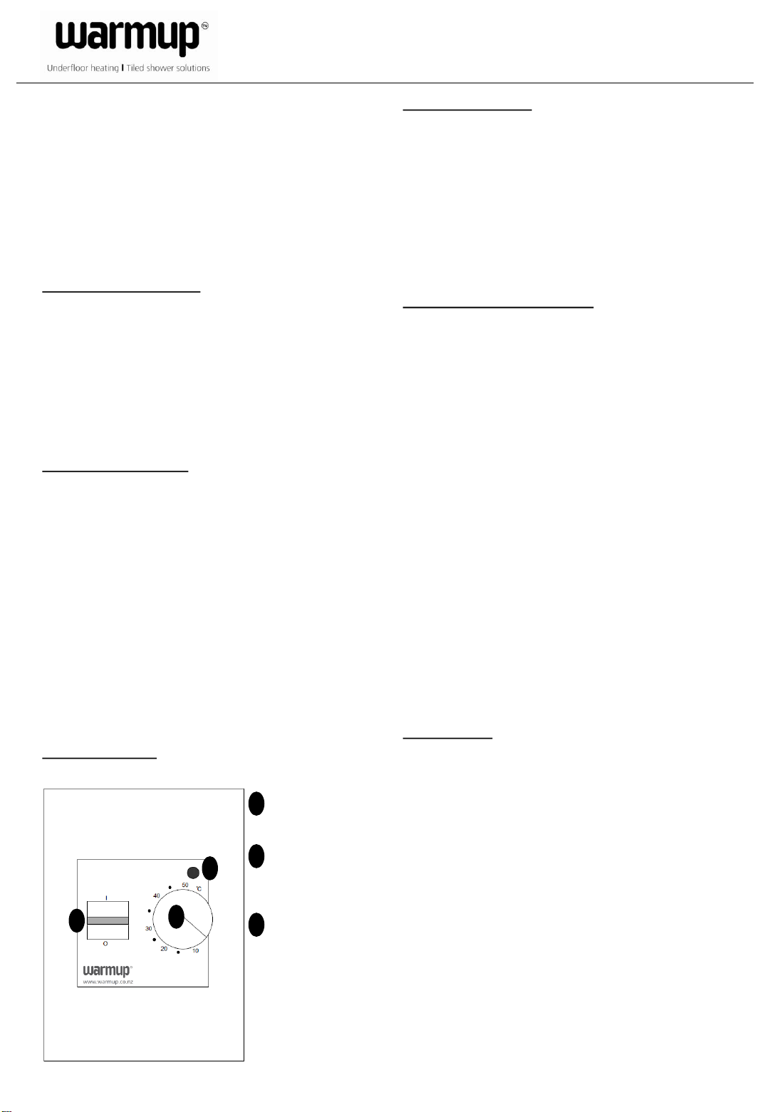
Operation Manual
3
1
2
On/Off
1
I – On O – Off
Temperature
2
setting
10 – 50⁰C
Indicator
3
The light is red
when the heat is
On.
Installation Instructions
MTC-1991-WU Electronic Thermostat
Temperature Setting
The thermostat has a scale range of 10-50⁰C. To assist
this adjustment, the thermostat has a LED which will
glow RED when the heating is ON. The thermostat
should be set to the maximum temperature setting
until the desired temperature of the room or floor is
achieved. The control knob should then be turned
back until the LED goes out. Fine adjustments can be
made over the next few days to suit individual
requirements.
Max/Min Temperature Setting
Behind the knob there are red and blue locking rings
held in position by a screw. To set the limitations,
loosen the screw (C) and adjust the red limit ring to
the desired maximum, set the blue ring to the desired
minimum temperature, then retighten the screw, The
knob must be re-installed exactly as it was removed.
Warning
The system must not be energized unless the system
is installed according to the instructions and the
installation meets all applicable codes. Warranty is
void if not installed according to this instruction
manual and proper procedure.
Caution: Disconnect all electrical power prior to
installing or servicing this unit.
Error Detection
The MTC-1991-WU has built-in error detection which
will de-energize the heating circuit if the sensor is
damaged or if it detects an open or shorted sensor
circuit.
Technical data
Power supply: 230-240V AC ±10%, 50Hz
Output relay, SPST (resistive load): 16A
Built-in switch: 2 pole, 16A
Ambient operating temperature: 0-50⁰C
Scale limitation: minimum and maximum
Scale range: 10-50⁰C
Temperature setback: not available
On/Off differential: 0.4⁰C
Enclosure: IP20
Dimensions: 115mm(h) x 84mm(w) x 50mm(d)

Figure 1 Figure 2
With floor sensor
Warmup New Zealand Limited
Copsey Business Park, 2/20 Copsey Place, PO Box 19144, Avondale, Auckland
T 0800 927 687 F 09 820 7090 E info@warmup.co.nz W www.warmup.co.nz
 Loading...