

Page 1

TECHNICAL HELPLINE
0845 345 2288
IMPORTANT
Read this manual before attempting to
install your undertile heate r.
Incorrect installation could damage the
heater and will invalidate your warranty.
by filling in your Guarantee
information online at
warmup.com
Installation Manual:
Undertile Heating
Loose Wire System
Page 2
3
4
5
6
8
9
10
11
12
14
15
16
19
Do’s and don’ts
Heater information
Making electric provision
Subfloor preparation
Wiring configuration
Installing multiple heaters
Installation step 1
Installation step 2
Installation step 3
Installation step 4
Installation step 5
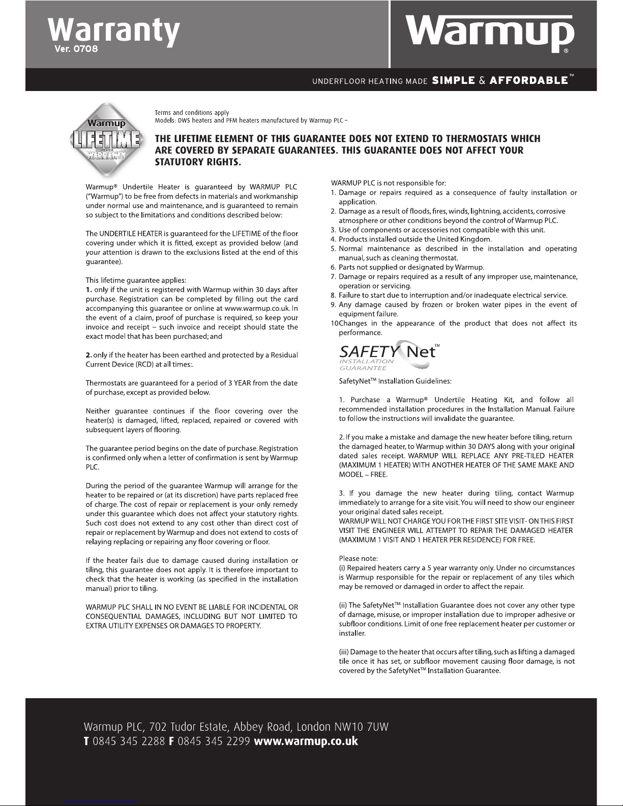
Guarantees
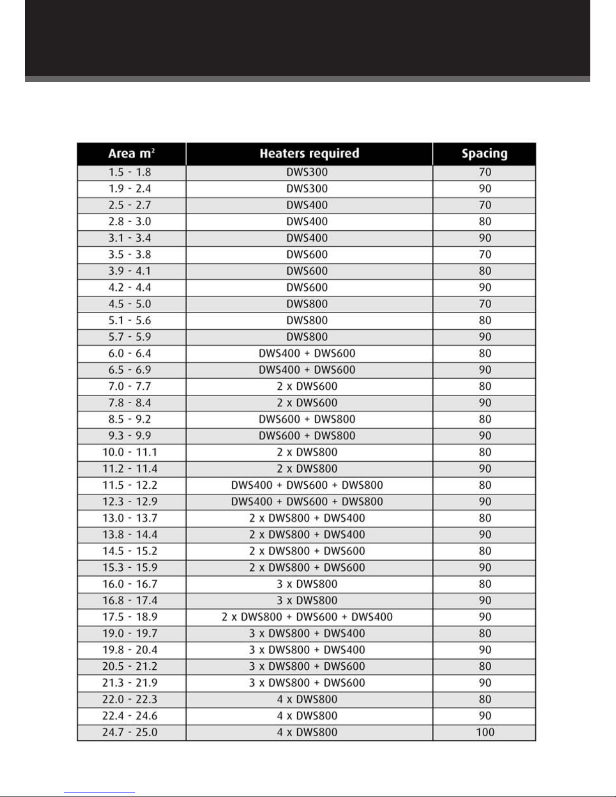
Sizing guide table
If these instructions are followed you should have no problems.
However, if you do require help at any stage, please call our FREE helpline:
Warmup Technical Helpline 0845 345 2288
You can also find a copy of this manual, wiring instructions, a list of frequently asked
questions and more helpful information on our website:
www.warmup.co.uk
Your Warmup®Undertile Heater
has been designed so that
installation is quick and straight
forward, but as with all electrical
systems, certain procedures
must be strictly followed.
Please check the sizing guide
at the back of this manual
to ensure that you have the
correct heater(s) for the area
you wish to heat.
Warmup plc, the manufacturer of the Warmup®Undertile
Heating System, accepts no liability, expressed or implied,
for any loss or consequential damage suffered as a result
of installations which in any way contravene the instructions
that follow.
Contents
2
Page 3

DO carefully read this installation manual before commencing installation.
DO ensure the floor surface is smooth, clean and dry before priming the floor with
Warmup
®
primer.
DO ensure good ventilation during application and drying of the primer.
DO lay the wires whilst the primer is still “tacky” to ensure the greatest level of adhesion.
DO plan the heater layout and installation so that any drilling after tiling (e.g. for fixing
sanitary ware) will not damage the wiring.
DO maintain a gap between heating wire runs of at least 50mm (2 inches) at all times.
DO make sure that ALL heating wire, including joints, are positioned under the tiles in the
installation.
DO protect the heating wire with cardboard or hardboard between installation and tiling.
DO use ceramic tile adhesives and grouts suitable for use with underfloor heating.
DO check that the heater is working immediately before commencing tiling.
DO take particular care when tiling not to dislodge or damage the heating wire.
DO ensure that each tile is solidly bedded in tile adhesive, with no gaps or voids beneath.
DO ensure that the heating elements are installed at least 50mm from conductive parts
of the building, such as water pipes.
DON’T install the Warmup
®
Undertile Heating System heater under any floor other than
ceramic, quarry or natural stone tiles.
DON’T commence installation on a concrete floor that has not been fully dried.
DON’T allow traffic over the primed floor or the installed heating wire before tiling.
DON’T cut or shorten the heating wire at any time.
DON’T allow the heating wires to cross over or touch each other at any point.
DON’T store tiles, sharp or heavy objects on any of the wiring whilst tiling.
DON’T commence tiling before testing the Warmup
®
Undertile Heating System.
DON’T switch on the installed heating system until tile adhesive has fully dried (7 days
minimum).
DON’T install the heating wire on stairways or up the walls.
DON’T install the mat in temperatures less than +5°C.
DON’T bend the heating cable under a 25mm radius.
The heating must be separated from other heat sources such as luminaires and chimneys.
WARNING
During the course of the installation care must be taken to ensure that no damage is caused by, for
example, falling objects, sharp objects, walking on the heating element. Once the heating wire has been
installed avoid all traffic over the wire until the floor has been tiled and the adhesive has set. Do not install
the heating wire until the floor is ready to be tiled. If the floor is not being tiled immediately, all heating
wires must be protected with two layers of cardboard or hardboard to prevent damage. Immediately prior
to tiling, test the heating wires as specified on page 14 to check it has not been damaged. If you are in
any doubt call the Warmup
®
Undertile Heating helpline on 0845 345 2288.
Do’s and don’ts
3
Page 4

The heaters consist of a fixed length of heating wire terminated at one end by a sealed joint
and the other end by a 3m power supply cable (cold tail).
The cores and earth braid are spliced in a waterproof joint assembly to the supply conductors
and the earth conductor of the cold tail.
Heater information
Heater Model Wire Colour kW Wire Length Amps Resistive Resistance
(m) (@230 volts) (ohms-cold)
DWS300 BLUE 0.300 22 1.3 176.0
DWS400 SILVER 0.400 34 1.7 136.0
DWS600 GREY 0.600 44 2.6 88.0
DWS800 RED 0.800 64 3.6 64.0
As with all electrical projects which are subject to Part P Building Regulations, all electrical work should be
carried out by a certified/qualified electrician. All work must conform to BS 7671:2008 and the current IEE
Wiring Regulations.
4
Page 5
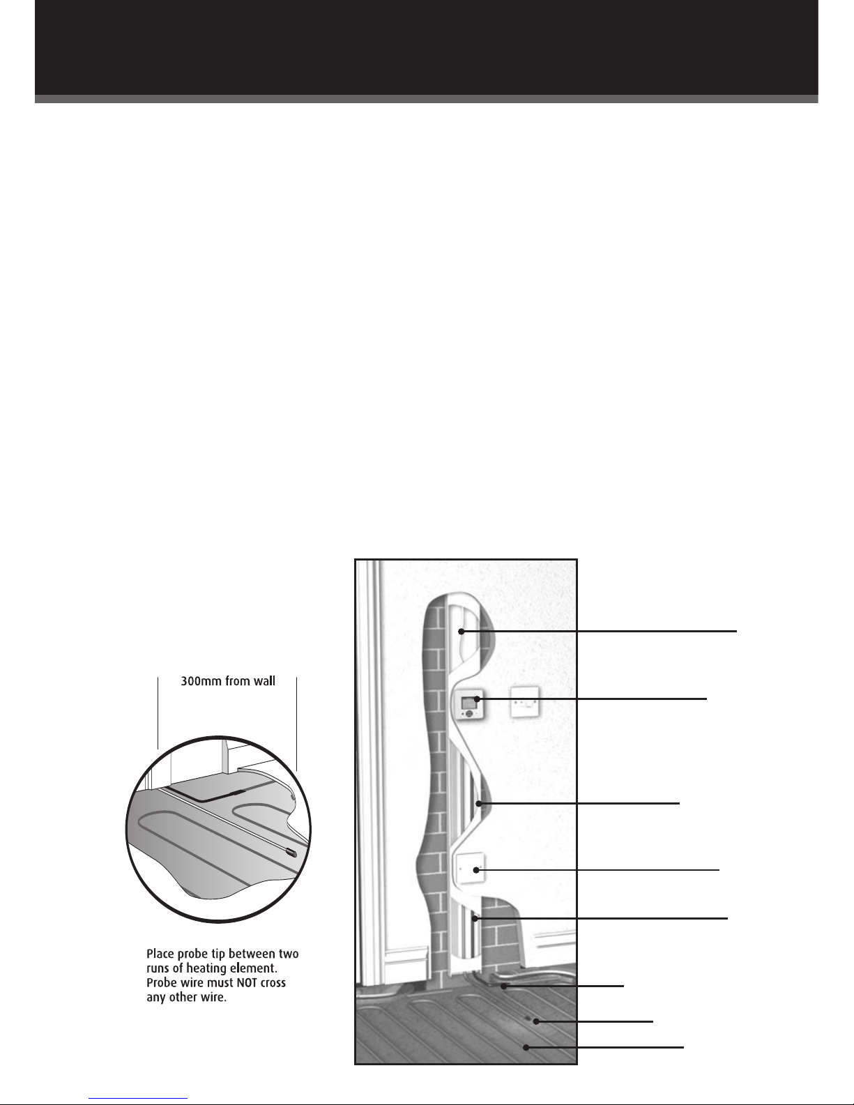
Install the RCD
The electrician must install a dedicated RCD or use an existing RCD. The electrician may wish
to use a combination ‘double pole switched’ fused-spur/RCD. No more than 4.8kW of
heating may be connected to each 30 milliamp RCD. For larger loads, use multiple RCD’s.
Note: It is possible to run the heater(s) from an existing circuit. The electrician will be able to determine whether or
not the circuit can handle the load and if it is RCD protected.
Install electrical boxes and trunking
You will require a deep (35mm) back box for the Warmup
®
Thermostat. If you are installing
more than two heaters, a junction box will also be necessary. The wiring to the thermostat
should be chased into the wall and protected by conduit or plastic trunking.
Connecting the Warmup
®
Thermostat
The thermostat should be connected to the main electrical supply via a fuse or circuit
breaker, ‘double pole isolator’ in accordance with the wiring regulations.
The thermostat should be installed within the rooms or area to be heated. In the case
of bathroom installations, electrical regulations prohibit the installation of the thermostat
within the bathroom itself. In such cases, the thermostat should be fitted to the outside
of an internal wall of the bathroom, as close to the undertile heating as possible, for example
in an adjacent airing cupboard.
Note: The floor probe wire can be
extended up to 50m.
Making electrical provision for the heater
Mains supply via RCD.
Fused isolator switch
must be fitted.
Warmup
®
Thermostat
mounted on the wall.
Wires recessed into
blockwork in metal
or plastic trunking.
Junction box.
(if more than 2 heaters)
Black power supply cable.
Temperature sensing
floor probe.
Heating element.
Joint.
5
Page 6

To fully utilise the long-term durability of ceramic tiling, whether heated or not, it is important
that the design, construction and preparation of the subfloor is carried out correctly.
It is essential that the subfloor be sufficiently rigid to support the ultimate weight that
it will have to bear without movement or deflection.
The choice of products for subfloor preparation and tile will vary depending on the existing
subfloor, preferred tiling system and choice of tile. This document is only intended to
be an outline guide to laying ceramic floor tiles. Further help regarding floor preparation
and tile application is available from the tile adhesive manufacturers.
Comprehensive information can be found in the following British Standards with which
all installations should comply:
BS 7671: "The IEE Wiring Regulations" (latest edition)
BS 8204: "Concrete bases and screed to receive in-situ flooring" 1987
BS 5385: "Wall and floor tiling" Part3: 1989 and Part 4: 1992
BS 8000: "Workmanship" Section 11.1:1989 and section 11.2:1990
Copies can be obtained from: British Standards Institute, 389 Chiswick High Road, London,
W4 4AL Or for a token fee, may be viewed at most Public Libraries. Ensure the most
up-to-date versions are seen. Alternatively, you may wish to seek professional advice;
e.g. an architect.
Subfloor Preparation
Prior to installation, it is important that the subfloor is properly prepared.
Timber subfloor: boards must be overboarded by a suitable tile-backer board or overboarded
with WBP plywood (18mm thickness minimum) screwed down at 200mm centres.
Insulated concrete floor: This must be completely dry (can take 8 weeks), smooth and level.
Subfloor previously covered in vinyl, cork or carpeting: all old flooring and adhesive must
be removed.
If bitumen asphalt is present as adhesive residues it must be removed. If the bitumen is a
damp proofing layer, it must be covered with a minimum 50mm of sand/cement screed,
taking care not to puncture the bitumen coating. The screed must be fully dry (6 weeks)
before priming.
If using other damp proofing or tanking systems, contact the manufacturer for advice.
Note: Chipboard, M.D.F. and O.S.B. boards (flake boards) are not suitable bases for ceramic floor tiling.
Technical notes
6
Page 7

Preparation of timber or concrete subfloor
Using WBP plywood
Ensure adequate underfloor ventilation.
Securely fix existing floorboards and if
necessary, pre-level with a latex/cement
self-levelling compound to give a flush fit
for the subsequently applied WBP plywood.
Refer to BS 5385: Part 3, clause 14.4
regarding sealing the backs and edges
of the WB plywood before fixing.
Fixing ply directly to the joists will not
provide a sufficiently stable floor finish
to accept tiles; fitting tongue and groove
flooring and then over-boarding with ply
or a tile backer board is recommended.
A rigid base is essential.
The above recommendations apply to floors
of small areas as advised in clause 14.4 of
BS 5385: Part 3: 1999.
Using insulated tile backer board
Fix the tile backer board as per
manufacturer’s instructions.
For best results and for ease of installation,
Warmup recommends the use of an
extruded polystyrene building or insulated
tile backer board with a cement-based
facing, such as Warmup
®
Insulation Board.
After attaching the board to the subfloor, the
Warmup®Undertile Heating System may
be laid directly on top of the tile backer/
building board, and then tiled over. It is
important to ensure that the tile adhesive
and grout used are flexible and that the tile
backer/building board has been fitted as per
the manufacturer’s instructions. High quality,
cement-based adhesives with their flexible
additives are most suitable.
NOTE: Do not use the green Warmup
®
primer
when installing on insulated tile backer board.
Tiles Flexible tile adhesive
Heating wire Primer
18mm WBP plywood or Warmup
®
Insulation Board
Tiles Flexible tile adhesive
Heating wire Warmup
®
Insulation board
Insulation board adhesive
Subfloor
(concrete or timber)
1
2
3
4
5
1
2
3
4
5
6
2
1 2
3 4
5
1
3
4
5
6
7
Page 8
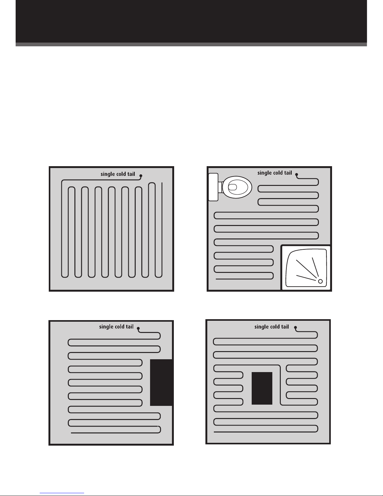
Whilst the installation instructions only make provision for the wiring to be installed in a
set configuration, there are many instances where departure from this configuration may
be desirable. Below are a few drawings illustrating the versatility of the
Warmup®Undertile
Heating System.
In each of the examples the floor space is heated using different wire configurations to suit
the particular layout of the room. It should be noted that whilst the sizing chart provided
in this booklet is a useful guide to heater layout, it may be necessary to slightly alter the
heating wire spacing to suit your particular installation. However, at no time should the
spacing between the wires be less than 50mm.
Wiring configurations
Standard room
Room with recesses
Room with central obstacle
Bathroom
8
Page 9
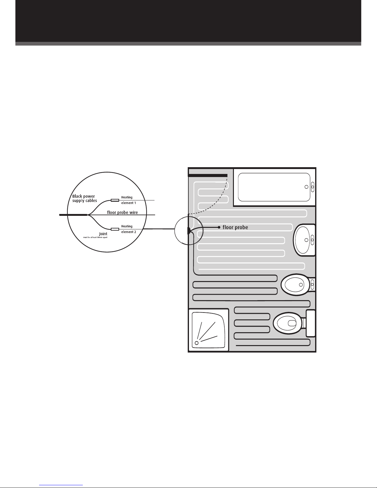
When installing two or more heaters, begin by reading the sizing guide at the back of this
booklet to ensure that you have the proper number and size of heaters for the area you
wish to heat. The sizing guide will also tell you the perimeter and heating wire spacing
required for your particular room size.
After you have primed the subfloor, mark the subfloor as per the instructions on page 11
and lay the first heater. Do not cover the first heater with tape at this point as you may wish
to slightly alter the spacings later on.
Lay the second heater in the remaining area using the same perimeter and heating wire
spacings as the first heater. Please note that all heaters will start in the same area next to
the Warmup
®
Thermostat location.
When laying more than one heater, it is important to keep these points in mind:
1 The heating wires may not touch or cross at any point.
2 The heaters are joined in parallel only at the Thermostat or in a junction box.
Do not attach one heater to another in series.
3 The heating wire spacings for all heaters in an area should be approximately equal.
Installing multiple undertile heaters
9
Page 10
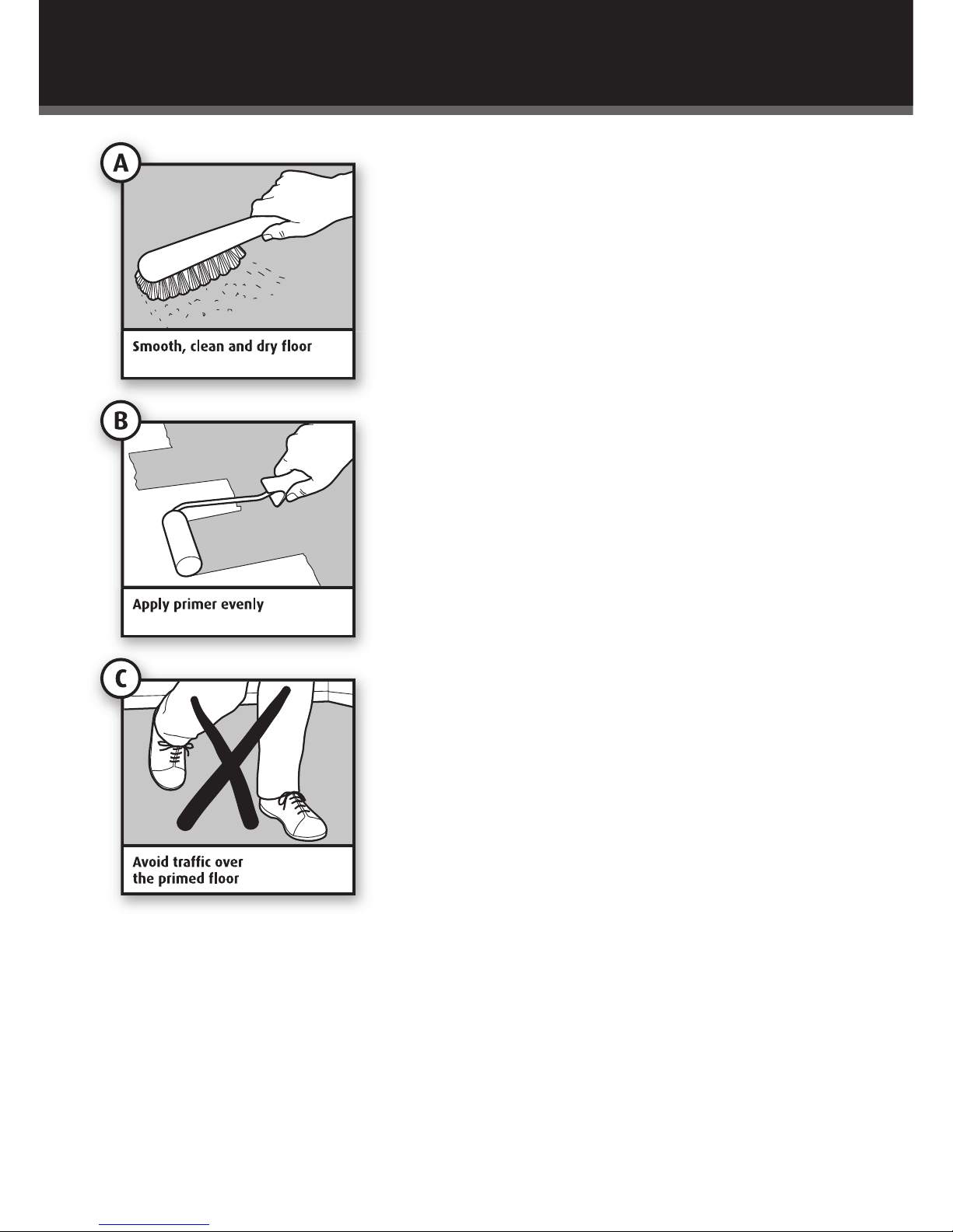
Paint the subfloor with Warmup®primer.
NOTE: It is not necessary to use the primer if you are
installing the heaters on an insulated tile backer board.
If the heater is being fitted to a wooden floor, the floor
should be boarded over with tile backer board or plywood
as specified in the technical notes section.
Before applying the primer ensure that the floor surface is
smooth, dry and free from dust or grease.
If necessary, an appropriate smoothing compound should
be applied and allowed to cure.
If the heater is being fitted to a solid floor it is essential
that the concrete has been allowed to dry before the
primer is applied. This can take 8 weeks or more.
If tiling on existing ceramic or quarry floor tiles, clean
the floor with an appropriate floor-cleaning compound.
Do not then apply the green Warmup
®
primer, go to step 2.
Using the roller supplied, apply the primer evenly to the
entire surface to be heated.
The primer must be allowed to dry for a minimum of
3 hours. The light green colour of the primer will change to
a darker green once dry.
Good ventilation must be provided, which along with
a higher ambient air temperature, will accelerate the
drying process.
Avoid traffic over the subfloor once the primer has
been applied.
*If any sort of sealant has been used on the base
DO NOT use the primer contained in the kit.
Installation step 1
10
Page 11
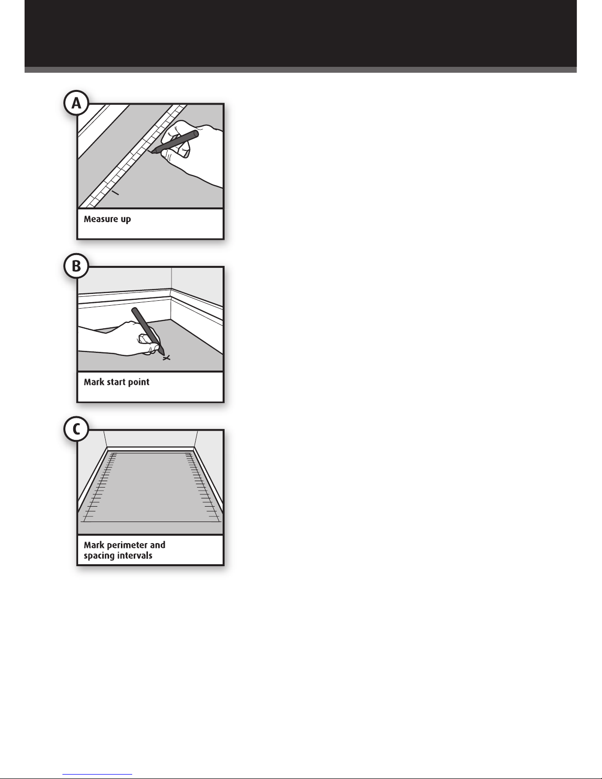
Installation step 2
Mark the heater position on the floor.
Calculate in square metres the size of the area to
be heated. Then, using the sizing guide on the back
of the manual, read off the wire spacing and perimeter
distances to correctly fit your heating wire into the
space available.
Using a fibre tipped pen, mark a start point as close
as possible to the power supply, but no further than
2.5m from it.
Mark all the outer corners of the heated area observing the
perimeter distances previously read off the sizing guide
and join the corners up to form a marked out perimeter.
Mark up the spacing intervals for the heating wire
following the sizing guide.
The spacing must be a minimum of 50mm and at no
time should the heating wire be less than 40mm from
the wall.
11
Page 12
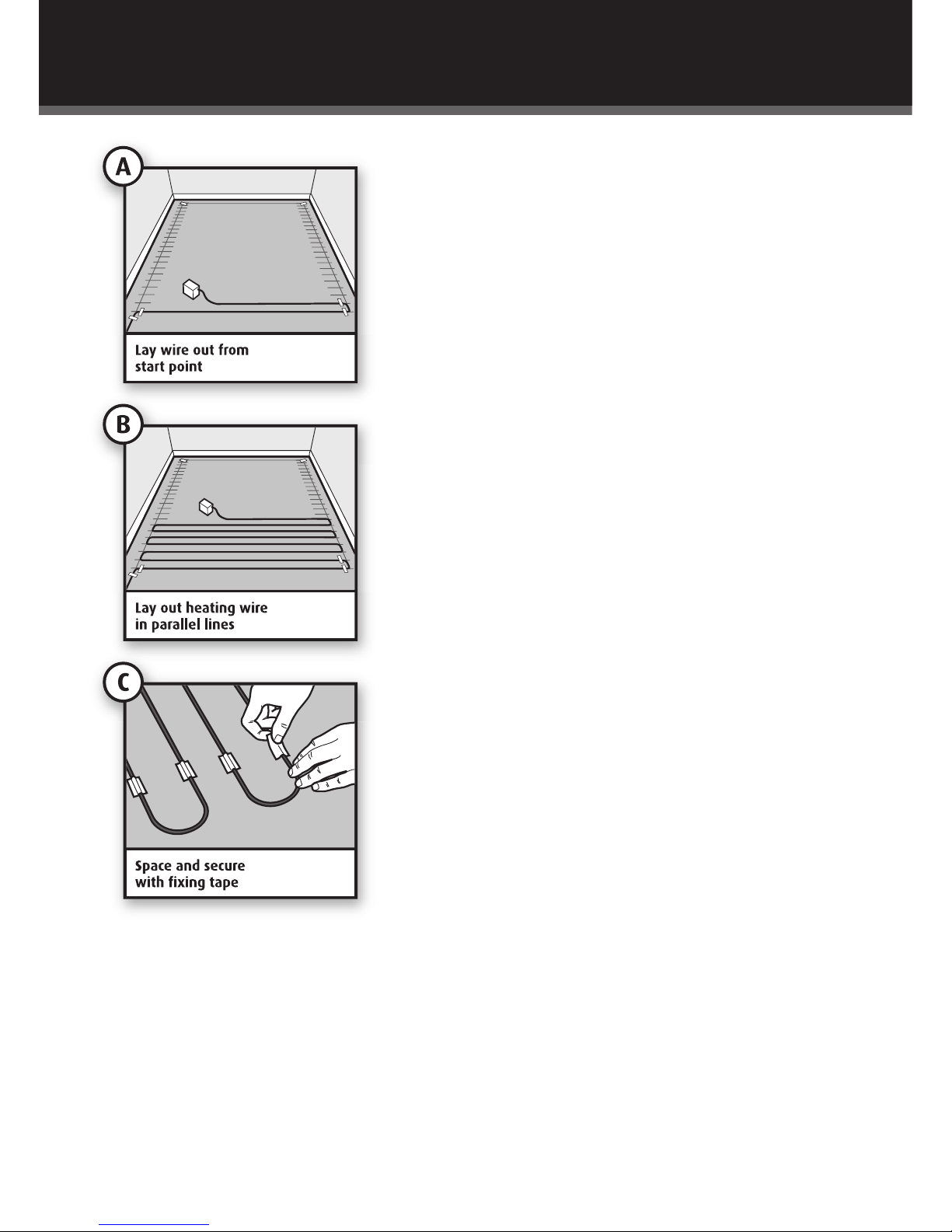
Installation step 3
Lay out heating wire and secure with fixing tape.
Once the floor has been marked up, the heating wire
can be laid out.
Gently pull the power supply cable from the box.
Do not remove the spool from the box as this will
cause the heating wire to twist.
After 3 metres of cable have been removed, you will
reach the point at which the power supply cable joins
the heating wire.
The joint should be taped to the floor at the start point.
The wire should be laid in parallel lines back and forth
across the main body of the area to be heated.
Using the wire spacing markings as tape down points,
secure the heating wire to the floor with strips of
adhesive tape supplied.
The strips should be about 25mm (1 inch) long.
In order to achieve even coverage of the balance of the
area to be heated, you may at this stage need to adjust
some of the wire spacing that you previously secured.
You may wish to alter the wire layout to fit your
particular room.
Where there are irregularities of room shape you can
manually lay out the heating wire, e.g. to provide warmth
around the basins, toilets, etc.
12
Page 13
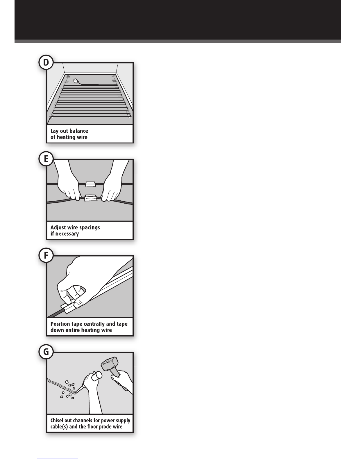
This is quite acceptable providing that:
The heating wires are spaced at least 50mm
apart at all times.
The heating wires never cross.
Once the heating wire layout has been completed, the
entire length of the heating wire should be taped to
the floor.
Ensure the greatest possible adhesion, with the minimum
of trapped air space beneath the taped wire. As you
apply the tape, gently tighten the heating wire from the
ends to ensure it is straight.
The wire should be located in the centre of the tape
to provide maximum protection from the tiler’s trowel.
If the tape is not completely covering the wire at any
point, apply another layer of tape to provide
additional protection.
After applying a length of tape, run your forefinger and
thumb along the length of the wire, gently squeezing
the wire to remove any air space between the wire
and the tape.
Depending on the requirements of the tiler, it may be
necessary to chisel out or "chase" short channels in the
subfloor to minimise the increased height presented by
the power cable, the end joint and the floor probe wire.
Before chiselling the area, ensure that the heating wire
and power supply cable are out of the way. Fit the power
supply cable into the channels and secure with fixing tape.
Remove all debris and chippings from the floor. Unless
the floor is being tiled immediately, cover the floor with
hardboard or cardboard to protect the heating wire.
Note: the main joint and end cap must be covered by adhesive and tile.
Do not tape over these joints as air pockets can occur and cause the joint
to fail due to overheating.
13
Page 14
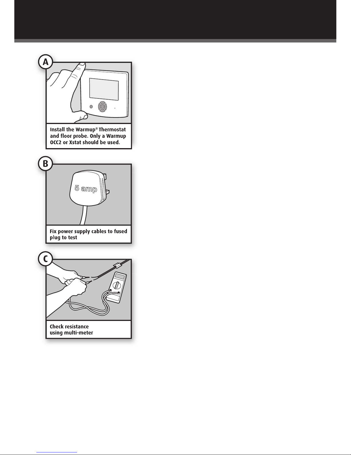
Installation step 4
Install the Warmup®Thermostat
and floor probe.
Instructions for the fitting of the Warmup Thermostat
can be found inside the thermostat box.
The power cable consists of conductors coloured brown
(live), blue (neutral) and green/yellow (earth). These
should be connected in accordance with current wring
regulations. For testing purposes, the brown and blue
wires should be connected to a multimeter to obtain a
resistance reading BEFORE any connections are made to
the electrical supply.
Please review the information on page 5 before proceeding.
Install Warmup
®
Thermostat and floor probe.
Test the heater*
Before tiling, ensure that the heater is working properly.
Temporarily wire each heater to a 5 amp fused plug via
an RCD, in accordance with normal wiring regulations.
Run each heater for approximately 10 minutes to ensure
that the element heats up and is warm to the touch.
In larger installations, where more than one heater is
fitted, repeat the procedure for each heater.
Do not leave the heater on for more than 30 minutes.
Completely disconnect the heater prior to and during tiling.
If possible, during tiling use a multi-meter set to 200 ohms
to check the resistance on the heater to ensure that there
is a circuit.
At 20 degrees C, the DWS300 heater should read
approximately 176 ohms, the DWS400 heater should read
approximately 136 ohms, the DWS600 heater should read
approximately 88 ohms, and the DWS800 heater should
read approximately 64 ohms.
A +/-5% ohm reading tolerance is allowed under
manufacturing guidelines.
If the heater is not working call the technical helpline
on 0845 345 2288.
At this stage DO NOT TILE if the heater is not working.
*DO NOT use a continuity tester to test the heaters.
14
NOTE:
DO NOT WIRE TO MAINS WHILE
HEATING ELEMENT IS STILL ON
THE REEL.
Page 15
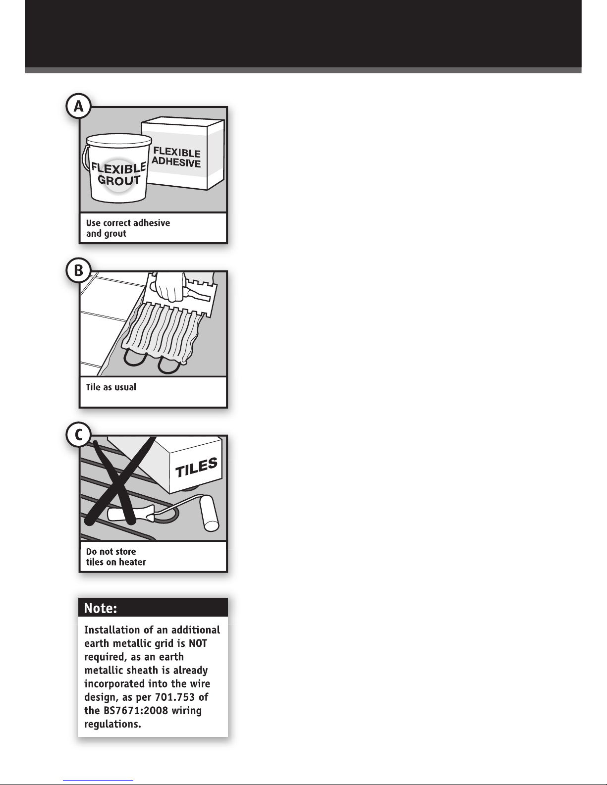
Installation step 5
Tile and grout
The tile adhesive and grout must include an additive for
flexibility and be suitable for use with underfloor heating.
Refer to the tile adhesive manufacturer’s instructions
for usage. 2 part flexible adhesive is best.
Check that the heating wire is fully taped and secure.
Tile as normal, taking care not to damage or dislodge
the heating wire with the trowel or with the tiles.
If tiling with mosaic slate or similar tiles, it is advisable
to cover the heating wire with latex self-levelling
compound before tiling.
When using a notched trowel, gently comb the adhesive
in straight lines in the same direction as the runs of the
heating wire. The trowel should be used at an angle of
approximately 45 degrees to the floor. If possible use
a plastic trowel.
Do not allow the trowel to make contact with the heating
wire whilst applying the adhesive. Use sufficient adhesive
to ensure that there are no voids or hollows under the tile.
If a tile has been positioned incorrectly, take great care
not to damage the heating wire when lifting.
Remember that tiles must not be lifted once the adhesive
is dry, as this will damage the heating wire. Do not store
or cut tiles on top of the heating wire. Do not allow
chippings or dust to contaminate the floor during tiling.
Care must be taken not to damage the heating wire during
the tiling process. Use a piece of carpet or a dustsheet as a
"crawl-board" to prevent the heating wire being damaged
by your feet or knees during the tiling process.
If possible, check the heater resistance with a multi-meter
every half hour or so. If the heater goes open circuit
(no reading on the multi-meter) DO NOT CONTINUE
– call the technical helpline on 0845 345 2288
Grout the floor as soon as possible as per the ceramic tile
adhesive manufacturer’s instructions. Do not switch on the
heater until the tile adhesive has fully dried. (min. 7 days).
15
Page 16

Notes
16
Page 17
Page 18
Name
Address
Post code Telephone number
E-mail
Installer name
Date of purchase Batch No. Serial No.
Please state which room the heater(s) is installed:
I hereby confirm that I have read and understand the contents of the Installation Manual, and that the heater has been installed as specified therein.
I acknowledge that no claim can be brought against the manufacturer or its agents for any consequential loss o
r damage whatsoever.
I confirm that the heater was working prior to the commencement of tiling.
Signed Date
other
Kitchen
Bathroom
Conservatory Hall
Fill in your registration online at www.warmup.co.uk to choose your FREE GIFT.
Page 19
The WARMUP word and associated logos are trade marks. © Warmup Plc. 2007 – Regd. TM Nos. 1257724, 4409934, 4409926,
Page 20
V0708
Sizing guide If your area is above 25m2 please contact the Warmup Technical Helpline on 0845 345 2288 for assistance
NOTE: All spacing has been based on square areas for calculation purposes. Therefore, actual spacing will vary according to
the shape of the area to be heated.
The standard perimeter spacing is 50mm.
However, it may be increased to a maximum of 150mm or decreased to a minimum
of 40mm.
Page 21
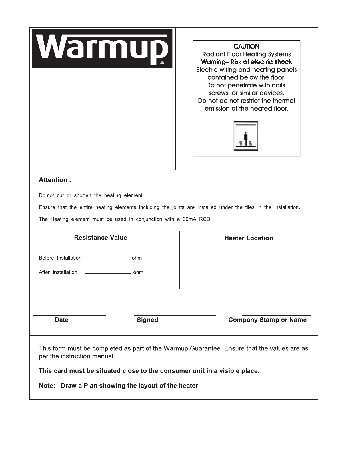
Heater Location:____________________________
Total Wattage:______________________________
Warmup PLC
702 Tudor Estate, Abbey Road,
London NW10 7UW.
T: 0845 345 2288
F: 0845 345 2299
W: www.warmup.co.uk
 Loading...