

Page 1

™
The w
orld’s best-selling electric floor heating brand
™
The w
orld’s best-selling electric floor heating brand
WARMUP INC.
USA: us@warmup.com
Tel.: 1-888-927-6333
www.warmup.com
CANADA: ca@warmup.com
Tel.: 1-888-592-7687
www.warmup.ca
CDP-2 SNOW SENSOR CONTROL/DISPLAY PANEL
INSTALLATION INSTRUCTIONS
CAUTION: Read all instructions carefully before installation.
Save this Installation Manual for future reference.
GENERAL SAFETY INSTRUCTIONS
1. THIS UNIT SHOULD BE INSTALLED BY QUALIFIED PERSONNEL ONLY!
2. To avoid shock hazard do not open the front cover of the attached
rain/snow sensor controller with power connected to the controller
or any controlled equipment.
3. Always open any circuit breakers and remove power from any high
voltage electrical circuits installed in close proximity to or sharing an
enclosure with the CDP-2 prior to removing the enclosure cover plate.
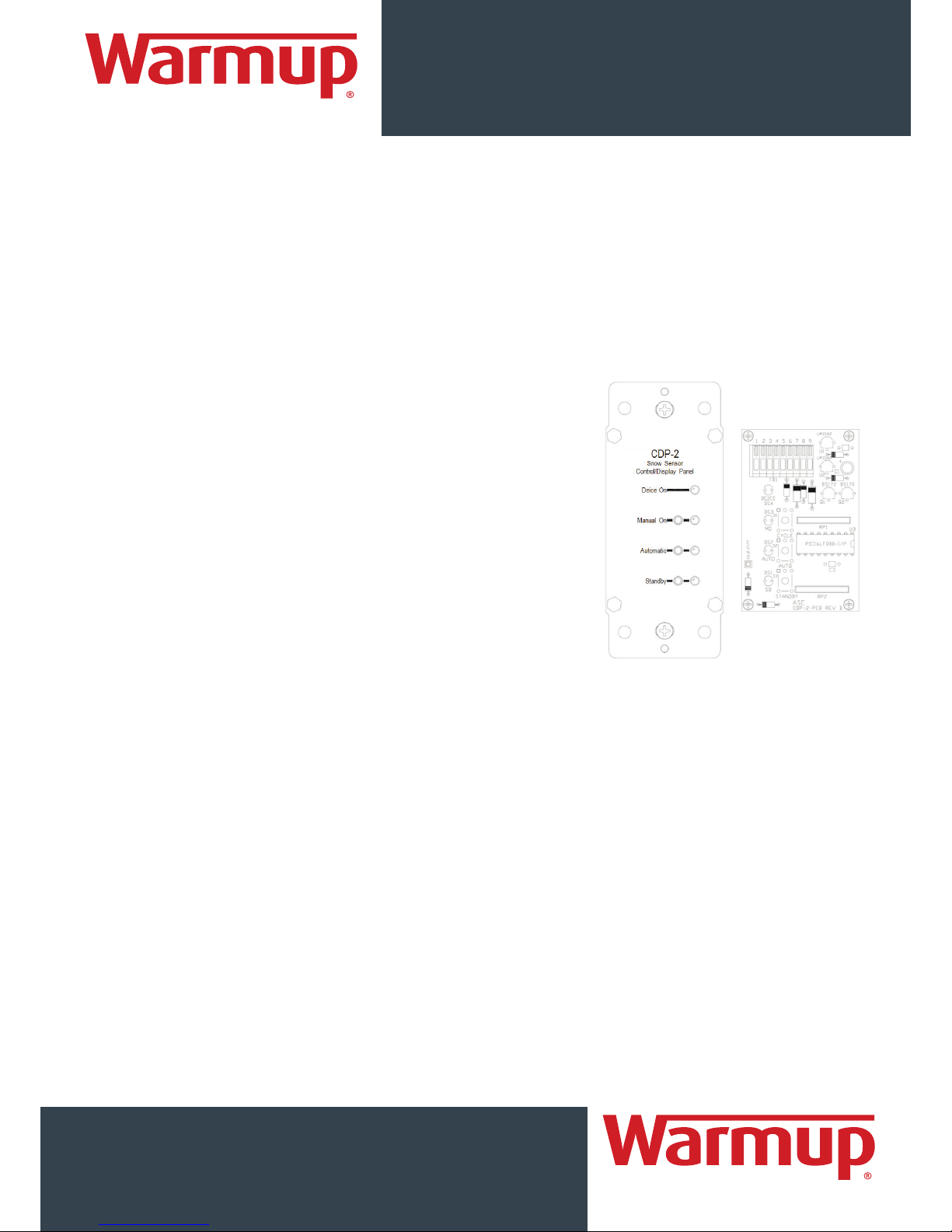
OVERVIEW
The CDP-2 Snow Sensor Control/Display Panel is used in conjunction with a DS-2C or DS-5 Rain/Snow
Sensor Controller. The sensor is typically mounted on a roof, near a gutter, or in a similarly difficult location
to reach. The CDP-2 provides a method of remotely monitoring and controlling the attached sensor. The
user may monitor both the operating mode and the activation state of the sensor. The user may also set
the sensor to prohibit automatic operation, to automatically operate, or to manually operate one snow
melting cycle, then return to automatic operation. The CDP-2 derives its power from the snow sensor and
requires no batteries or AC power. With an operating temperature range of -40°C to +85°C the CDP-2 is
designed for use either indoors or outdoors with proper protection from the elements.
INSTALLING THE CDP-2 CONTROL/DISPLAY PANEL
Installation requires a CS-1 Remote Control/Monitor Pigtail for the snow sensor and an appropriate 5conductor cable for installation between the snow sensor and the CDP-2. The cable conductors must be
tinned, stranded, minimum 22 AWG copper and overall shielding is required. An appropriate selection is
Belden® 9941 or equiv. The CDP-2 can be installed as much as 500 feet away from the snow sensor if
proper cable is used. Remove all power to the snow sensor, open its cover, and install the CS-1 pigtail.
Install the 5-conductor cable between the sensor and the CDP-2 enclosure. Ground the “drain” wire on
one end only and terminate the cable leads to the CS-1 following the table below:
CS-1 Color Function Your Color CDP-2 TB-1
Black Manual On 5
White Return 6
Green Standby/Reset 7
Orange Deice On Mon 8
Red Deice On Mon 9
The CDP-2 may be installed in a conventional single or multi gang standard electrical enclosure. If installed
in a multi gang enclosure next to high voltage equipment the CDP-2 and its interconnecting cable must
be isolated from high voltage wires and devices. Consult local electrical codes to determine the isolation
methods required. Remove 2 in. (50mm) of outer insulation and shield from the 5-conductor cable.
Remove ¼ in. (6mm) of insulation from the individual inner conductors.
Following the above table press the clamp button on the terminal block, insert the bare lead into the
clamp hole, then release.
Page 2
™
The w
orld’s best-selling electric floor heating brand
WARMUP INC.
USA: us@warmup.com
Tel.: 1-888-927-6333
www.warmup.com
CANADA: ca@warmup.com
Tel.: 1-888-592-7687
www.warmup.ca
™
The w
orld’s best-selling electric floor heating brand
CDP-2 SNOW SENSOR CONTROL/DISPLAY PANEL
INSTALLATION INSTRUCTIONS
The CDP-2 faceplate can be grounded to reduce the chances of damage due to static shock. This can be
an important consideration when operating in a very dry environment in the winter. Remove 1 in.
(25mm) of insulation from the green EGND lead and connect this lead to an electrical ground lead using
a wire nut or equivalent.
Install the CDP-2 into the electrical enclosure using the two screws provided. The screws are compatible
with both metallic and non-metallic enclosures. Once installation is complete a “modular” electrical cover
plate can be installed. Compatible types include the Leviton® Decora® and Hubbell® Styleline series.
EXTERNAL CONTROL/MONITOR OPERATION
The CDP-2 indicators show the current setting of the manual override
switch for the attached snow sensor, either MANUAL ON, AUTOMATIC,
or STANDBY. The sensor override switch will also override any current
CDP-2 commands. Whenever the sensor’s switch overrides the CDP2’s setting, then returns to AUTOMATIC mode, the CDP-2 will also
return to AUTOMATIC mode. The sensor override switch should be
left in the center AUTOMATIC position to allow the CDP-2 to control
the system.
The CDP-2 provides three pushbutton switches; STANDBY, AUTOMATIC,
and MANUAL ON. The respective LED indicators for each control
reflect the current operating mode of the snow sensor. Note that,
to save energy, the LED indicators blink periodically rather than
remaining steadily illuminated.
Pressing STANDBY will set the connected snow sensor to ignore snow fall and prohibit automatic the CDP2 is designed for use either indoors or outdoors with proper protection from the elements.
A “Delay Off” drying cycle time is configured on the snow sensor with a time delay of 30-90 minutes.
It begins once snow stops falling and allows the heated surface to more thoroughly dry. For example, if the
cycle is set for 30 minutes and snow falls for 2 hours the snow sensor will operate the snow melt system
for 2 hours, 30 minutes. Switching the sensor override switch to the MANUAL ON position will cause the
sensor to close its relay, illuminate the CDP-2 MANUAL ON and DEICE ON indicators, and activate the snow
melt system continuously. Pressing the MANUAL ON button on the CDP-2 will not trigger the sensor to
run continuously but will initiate one drying cycle. This mode can be used to test the system or clear any
remaining unmelted snow. This function allows the user to run a cycle without having to remember to
shut the system back off. The sensor will initiate one drying cycle and revert to automatic mode, ready
for detection. The MANUAL ON mode can be activated directly from either AUTOMATIC or STANDBY mode.
The user may clear the drying cycle by pressing STANDBY. Note that a properly working unit will not show
a MANUAL ON indication during this cycle but will show AUTOMATIC with a DEICE ON indicator.
The DEICE ON indicator shows whether or not the attached snow sensor has been activated and the snow
melting system is operating.
Page 3

™
The w
orld’s best-selling electric floor heating brand
™
The w
orld’s best-selling electric floor heating brand
WARMUP INC.
USA: us@warmup.com
Tel.: 1-888-927-6333
www.warmup.com
CANADA: ca@warmup.com
Tel.: 1-888-592-7687
www.warmup.ca
CDP-2 SNOW SENSOR CONTROL/DISPLAY PANEL
INSTALLATION INSTRUCTIONS
HOME AUTOMATION INTERFACE
The CDP-2 also includes an input for optional home
automation control. This interface provides the capability to
trigger the system through telephone or computer control.
Closure of the Trigger and Enable inputs will start one snow
melting cycle, just as though the MANUAL ON button was
pressed. Once the cycle is complete the sensor will revert
to AUTOMATIC mode.
The Enable input is an optional connection point for a
second “safety” contact set. If used, both contact sets
must close to trigger the snow melt system. This can help
eliminate inadvertent cycling of the system. If only one
contact set is available the user may install a jumper wire
across terminals 3 & 4. The user may also connect a simple
toggle switch across the Enable input to allow manual
enabling and disabling of the home automation interface.
LIMITED WARRANTY
The CDP-2 is warranted against defects in workmanship and materials for two years from date of sale.
This warranty does not apply to damage resulting from accident, misuse, or alteration nor where connected
voltage to the attached snow sensor is more than 5% above the configured operating voltage, nor to
equipment improperly installed or wired or maintained in violation of this Owner’s Manual. No other
written or oral warranty applies. No employee, agent, dealer or other person is authorized to give any
warranties on behalf of Warmup.
The customer shall be responsible for all costs incurred in the removal or reinstallation and shipping of the
product for repairs. Within the limitations of this warranty, inoperative units should be returned, freight
prepaid, to Warmup, and we will repair or replace, at our option, at no charge to you with return freight
paid by Warmup. It is agreed that such repair or replacement is the exclusive remedy available from
Warmup and that WARMUP IS NOT RESPONSIBLE FOR DAMAGES OF ANY KIND, INCLUDING INCIDENTAL AND
CONSEQUENTIAL DAMAGE.
Some states do not allow the exclusion or limitation of incidental or consequential damages so the above
exclusion may not apply to you. The warranty gives you specific legal rights, and you may also have other
rights which vary from state to state.
 Loading...