

Page 1
5iE
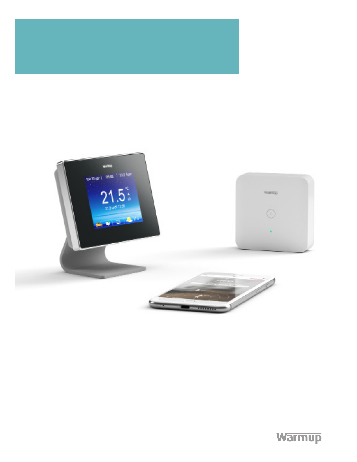
The Smartest Smart Thermostat
Installation Manual
Technical Helpline
0345 345 2288
Page 2

Contents
Components ..........................................3
Safety Information .................................. 4
Step 1 - Install Boiler Receiver ....................7
Step 2 - Assembling the 5iE ....................... 10
Step 3 - Paring and testing ....................... 12
Step 4 - Review Installation ...................... 14
Step 5 - Getting Started .......................... 16
Step 6 - Download ‘MyHeating’ app ............. 17
Step 7 - Registration ............................... 18
Step 8 - General information ..................... 19
Step 9 - Troubleshooting .......................... 20
Technical Specications ........................... 21
User Guide
Installation Guide
Page 3
5iE
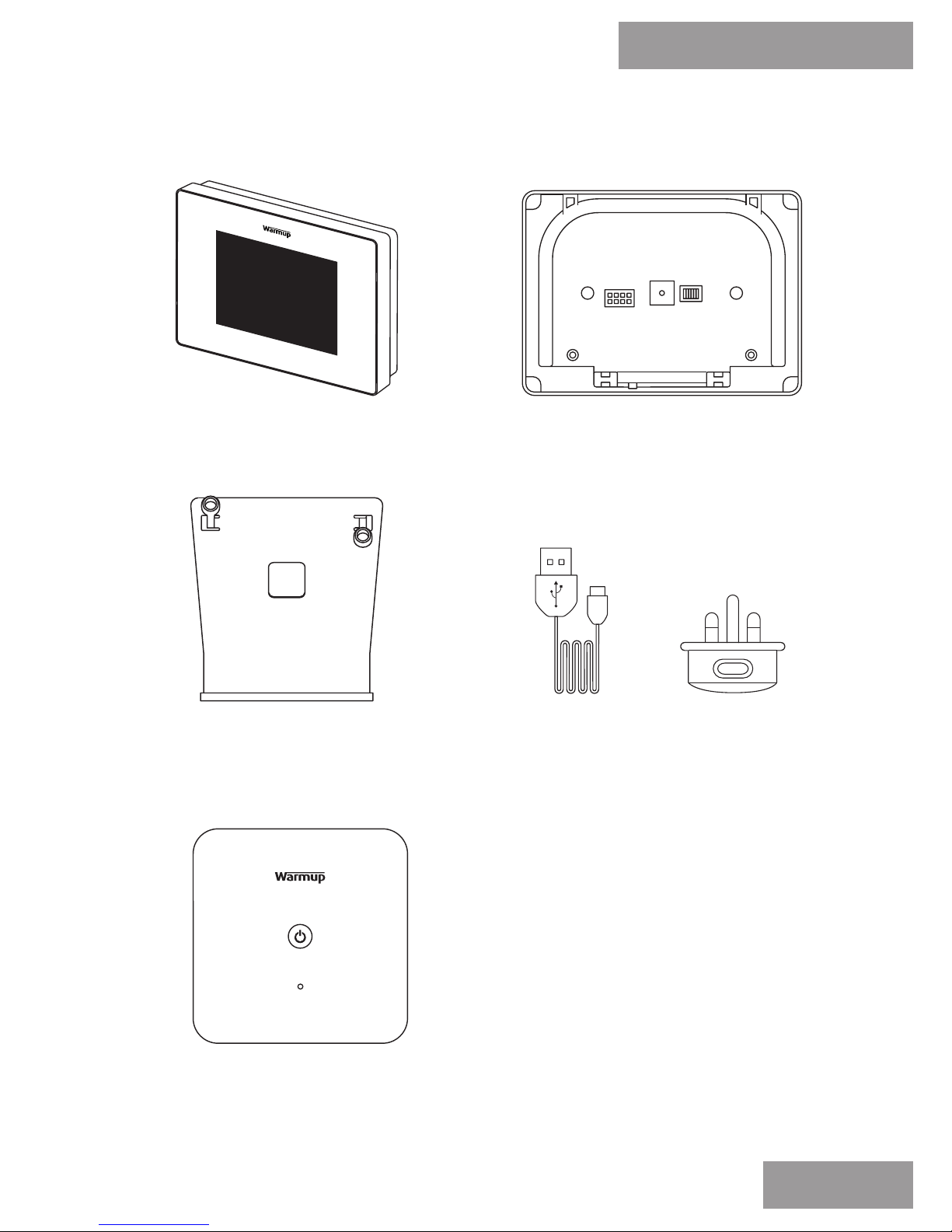
Components
Power BaseThermostat Face
Stand
Boiler Receiver
Power Adapter with 1m
USB Cable
Pack Contents
3
Page 4

IMPORTANT INFORMATION: Installation of the Boiler Receiver
should only be carried out by a qualied electrician. It requires a
permanent 230V supply.
The Boiler Receiver should be connected to the central heating
fused spur or circuit breaker in accordance with current wiring
regulations such that there is a single point of isolation for all
interconnected devices.
Isolate the central heating system from the mains supply
throughout the installation process.
Ensure that multi stranded wires are fully inserted into the
terminals and secured tightly. Any loose strands should be trimmed
as they could cause a short-circuit.
Safety Information
5iE
Safety Information
4
This product uses mains voltage electricity
and work should only be carried out by a
qualied electrician. Electrical installation to
be in accordance with latest edition of BS7671
Wiring Regulations and appropriate Statutory
Regulations.
!
Page 5
Before making any permanent xtures Warmup recommends
progressing through to ‘Step 3 - Paring and Testing’ upon
identifying preferred locations for the Boiler Receiver and Power
Base. This will ensure the wireless connection is not subject to
range or interference issues once installed.
The Boiler Receiver should be installed within the Boiler’s vicinity.
Large metal objects such as the boiler, hot water cylinder or
radiators, should be at least 300mm away from the Boiler
Receiver and not directly between it and the Power Base.
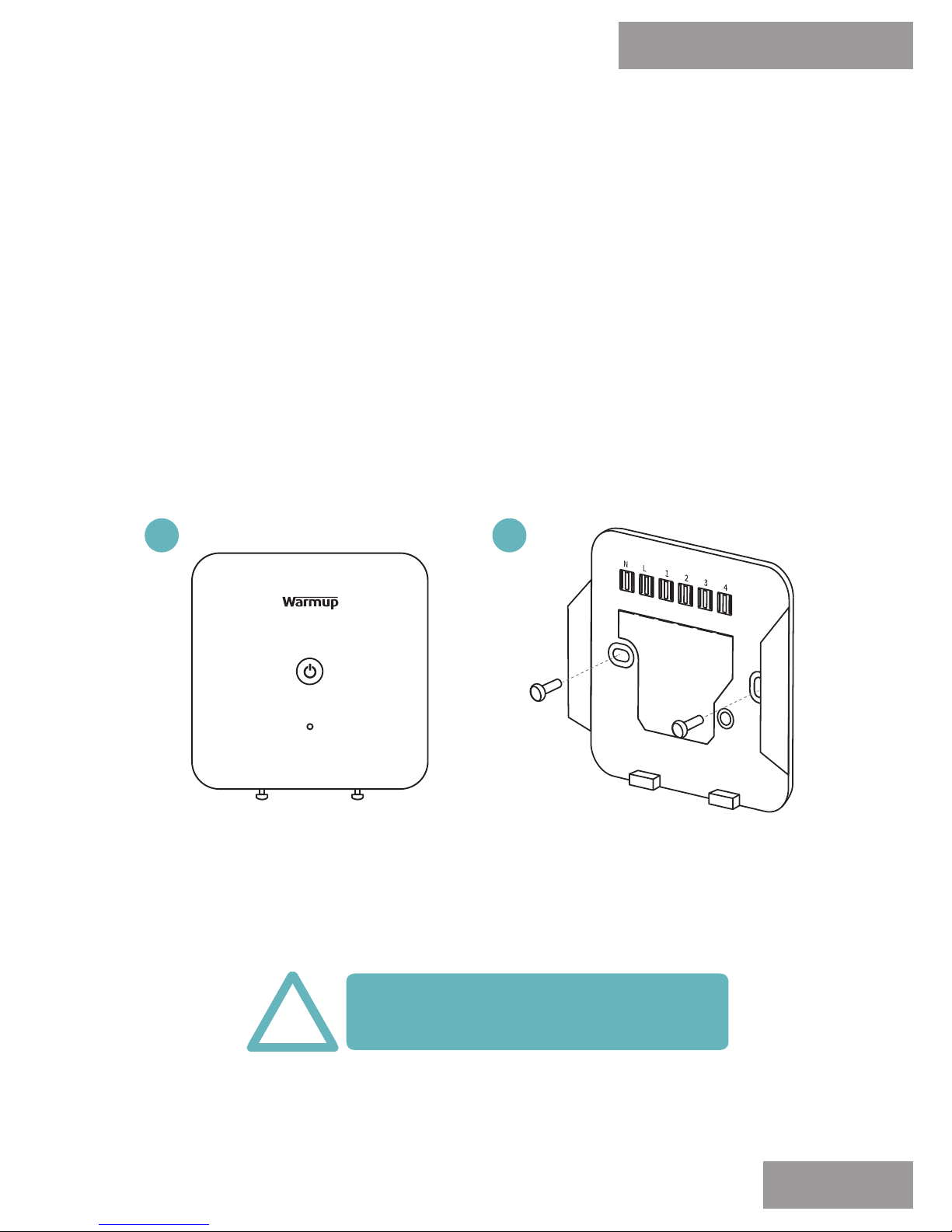
Loosen both screws at
the bottom of the Boiler
Receiver and remove
the backplate.
Fix the backplate to the
wall using xing screws
provided.
Make sure to avoid cables or pipes
which may be concealed in the wall
!
Mounting/positioning
5iE
Step 1 - Install Boiler Receiver
NOTE: For alternative installation congurations, see online at www.warmupsmart.com/installation
5
1
2
Page 6
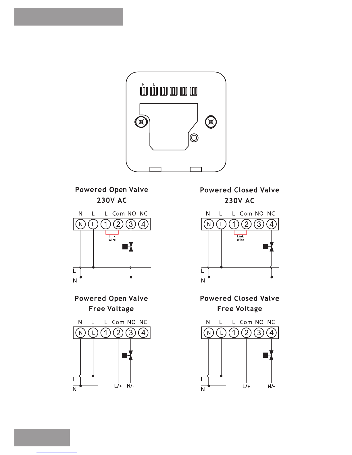
Wiring Connections
5iE
Step 1 - Install Boiler Receiver
6
NOTE: For alternative installation congurations, see online at www.warmupsmart.com/installation
1 2 3 4
Page 7
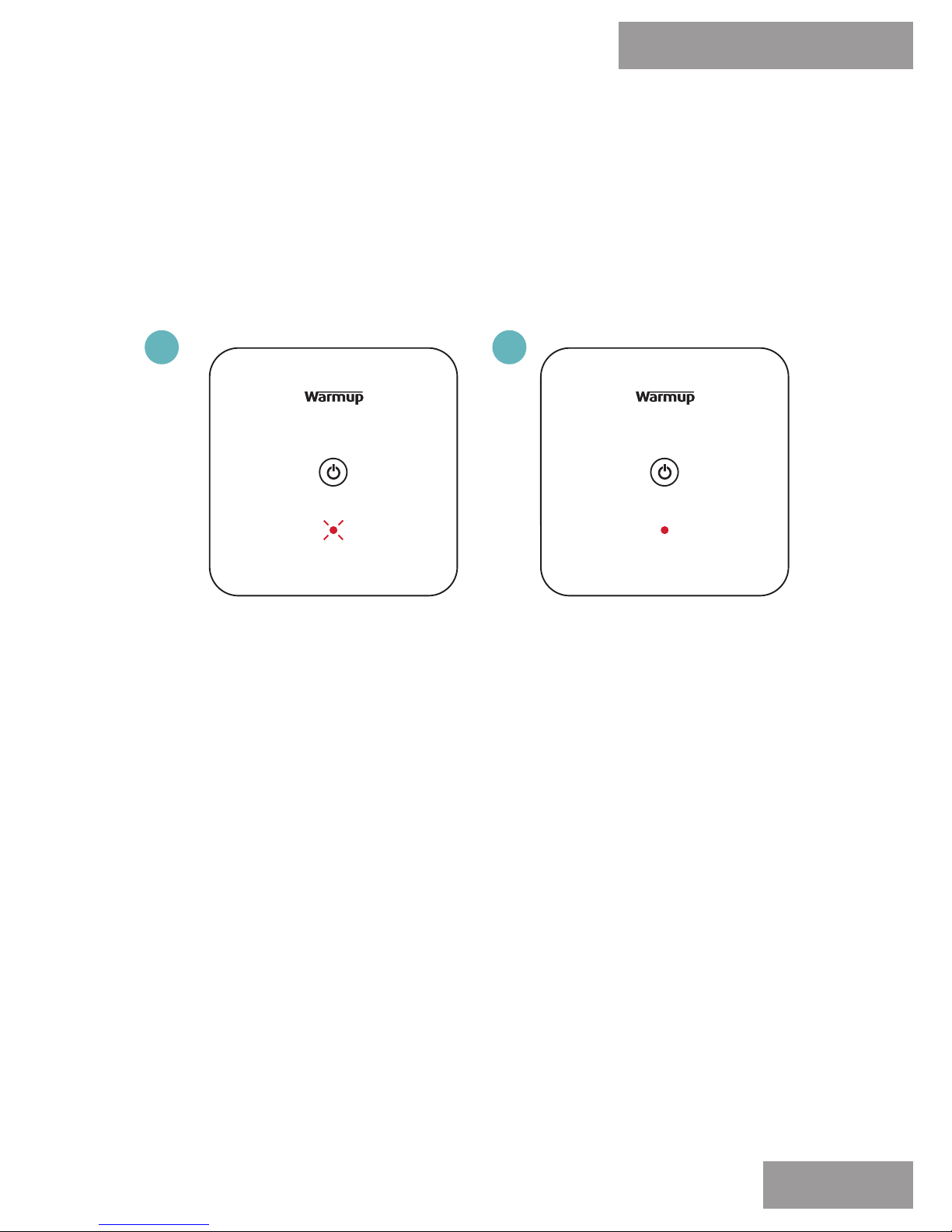
Once the Boiler Receiver has been wired correctly, reattach the
front panel to the back plate and tighten both screws to secure.
Restore power to the
boiler. The LED on the
Boiler Receiver will ash
RED slowly to indicate it
has power and is
not paired.
Test the manual control
function (Page 8) to
ensure the boiler is being
switched by the Boiler
Receiver.
Re-assemble
5iE
Step 1 - Install Boiler Receiver
7
1
2
Page 8
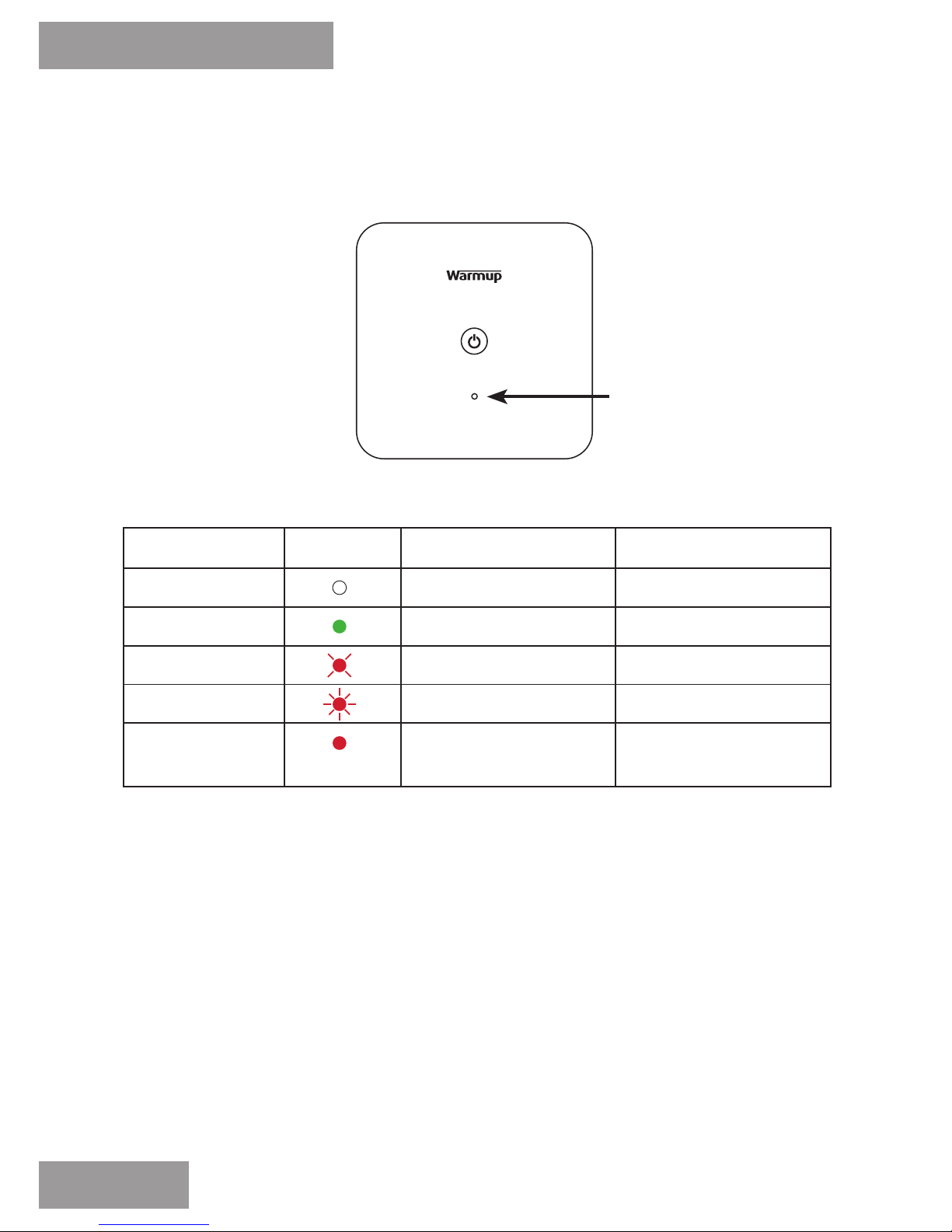
LED Colour LED Status Meaning
N/A Not lit Paired
Green Lit constantly Relay on
Red Flashing slowly Not paired
Red Flashing quickly Relay o
Red Lit constantly Communication Lost
Relay on
LED Status
5iE
Step 1 - Install Boiler Receiver
LED
8
Page 9

The Warmup 5iE has been designed to still provide heating control
should communication between the Power Base and Boiler
Receiver be interrupted.
With the Power Base and Boiler Receiver paired and the
Thermostat face calling for heat, the relay will be activated and
the Boiler Receiver will show a constant green LED indication. If
the communication between the Power Base and Boiler receiver
is lost, the green LED and relay will remain active on for the
Boiler Receiver for a period of up to 30 minutes.
If communication has not been restored before the 30 minutes has
expired, the Boiler Receiver will indicate a communications fault
by displaying a red LED ashing quickly.
To activate the Boiler Receiver manually (switch heating on), or
whilst communication has been lost, press the power button on
the Boiler Receiver once. The LED indicator with change from
ashing quickly red to constant red.
To de-activate the Boiler Receiver manually (switch heating o),
or whilst communication has been lost, press the power button
on the Boiler Receiver once. The LED indicator with change from
constant red to ashing quickly red.
Once communication has been restored, the Boiler Receiver
indication will change back to constant green when the
Thermostat face is calling for heat and the Boiler Receiver is
activated.
Manual Control
5iE
Step 1 - Install Boiler Receiver
9
Page 10
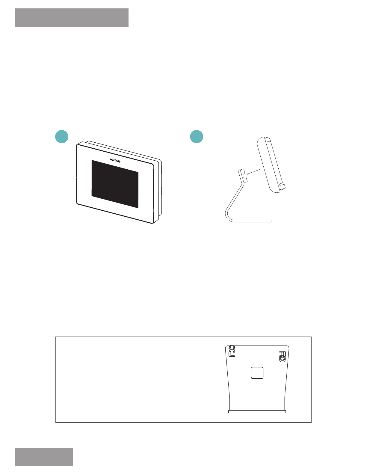
Remove the 5iE from its
packaging. Loosen both
closing screws located
at the bottom of the
Thermostat Face, and
remove from the Power
Base.
Clip the Power Base
onto the stand. Thread
the USB Cable through
the stand and connect
to the Power Base.
Connect the Power
Adaptor to a wall socket.
For optimal performance the Thermostat should be located
in an area with good ventilation. It should not be beside a
drafty window/door, in direct sunlight or above another heat
generating device (e.g. radiator or TV).
Stand Mounted
5iE
Step 2 - Assembling the 5iE
10
1 2
NOTE: For alternative installation congurations, see online at www.warmupsmart.com/installation
Components required:
· Thermostat Face
· Power Base
· Stand
· Power Adapter with 1m Cable
Page 11
5iE
Step 2 - Assembling the 5iE
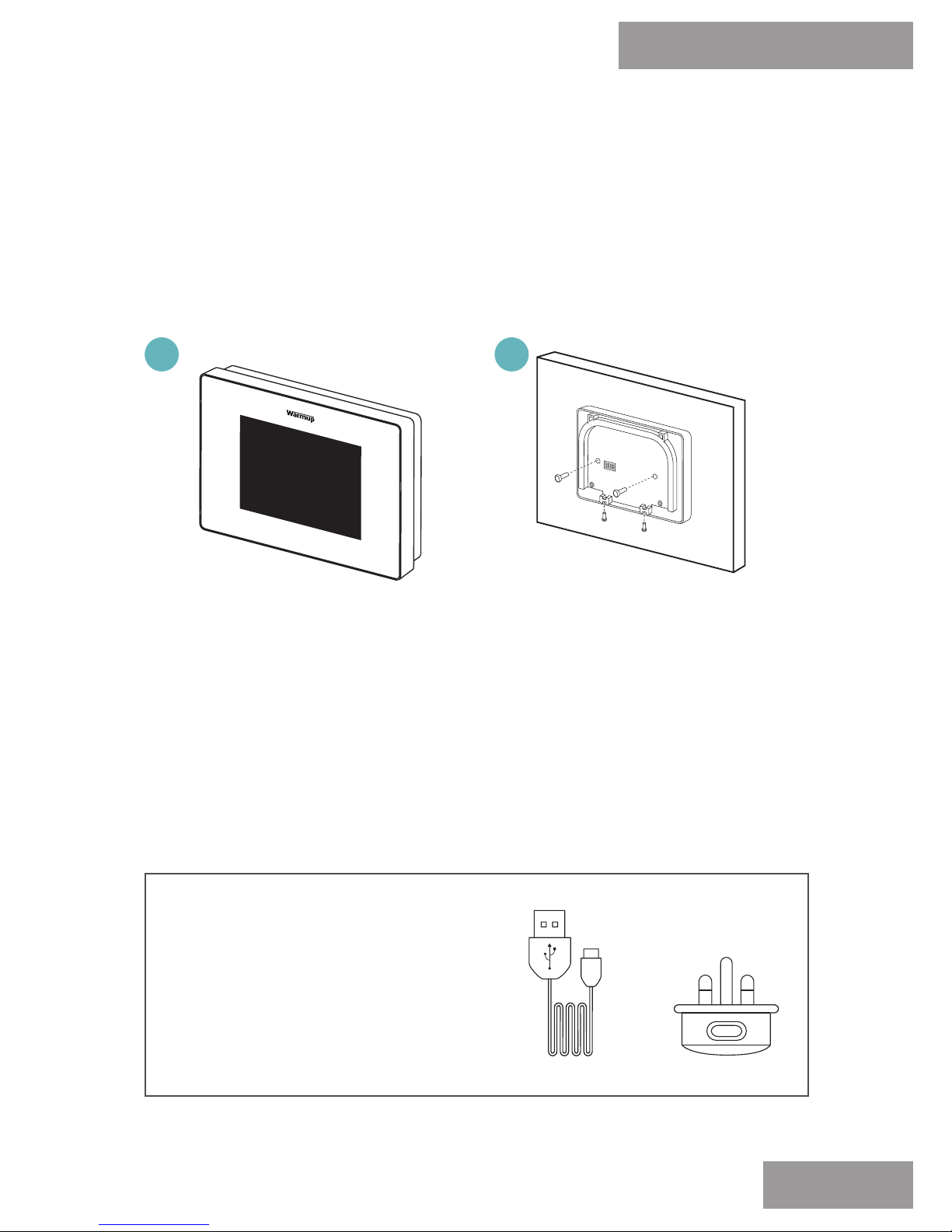
Remove the 5iE from its
packaging. Loosen both
closing screws located
at the bottom of the
Thermostat Face, and
remove from the Power
Base.
Drill a hole through the
wall to feed the USB
cable into the pattress.
Connect the USB cable
to the Power Base and
attach it to the wall
using the xing screws
provided.
For optimal performance the Thermostat should be located in
an area with good ventilation. It should not be beside a drafty
window/door, in direct sunlight or above another heat
generating device (e.g. radiator or TV).
Wall Mounted
11
1
2
NOTE: For detailed instructions, see online at www.warmupsmart.com/installation
Components required:
· Thermostat Face
· Power Base
· Power Adapter
· Extra: In-wall USB Cable
Page 12
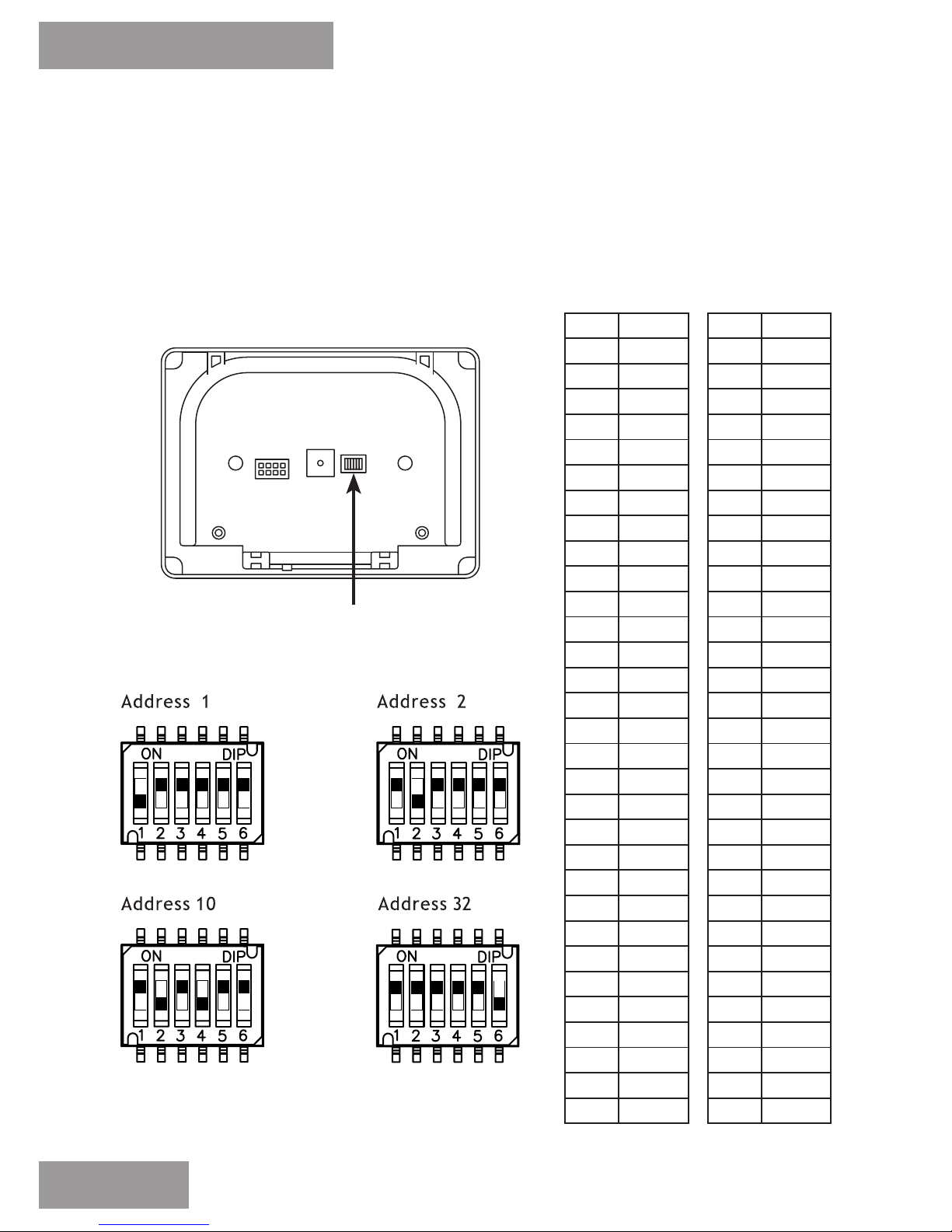
When using multiple 5iE’s, each Power Base should be set to a
unique address to prevent interference. Use the dip switches on
the power base to select the unique address for each 5iE.
Address Setup
Dip Switches
5iE
Step 3 - Pairing and Testing
12
1 100000
2 010000
3 110000
4 001000
5 101000
6 011000
7 111000
8 000100
9 100100
10 010100
11 110100
12 001100
13 101100
14 011100
15 111100
16 000010
49 100011
50 010011
51 110011
52 001011
53 101011
54 011011
55 111011
56 000111
57 100111
58 010111
59 110111
60 001111
61 101111
62 011111
63 111111
0 000000
33 100001
34 010001
35 110001
36 001001
37 101001
38 011001
39 111001
40 000101
41 100101
42 010101
43 110101
44 001101
45 101101
46 011101
47 111101
48 000011
17 100010
18 010010
19 110010
20 001010
21 101010
22 011010
23 111010
24 000110
25 100110
26 010110
27 110110
28 001110
29 101110
30 011110
31 111110
32 000001
Page 13
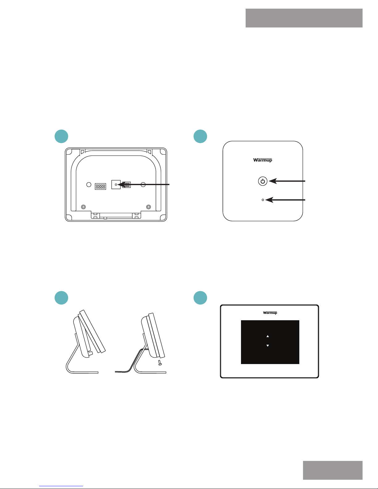
Before pairing, please make sure the Power Base and Boiler
Receiver are powered. If the LED on the Boiler Receiver is not
slowly ashing RED, indicating that it is ready to be paired, reset
its pairing by pressing and holding the power button for 6 seconds.
Paring
5iE
Step 3 - Paring and Testing
13
The LED on the Boiler
Receiver will stop
ashing RED, indicating
a successful connection.
Following the on-screen
instructions, join a WiFi
network, record device
number on page 17 of this
manual. Test operation.
Press the Pairing Button
on the Power Base, as
shown above, using a
short length or wire or
similar to begin pairing
Power
button
LED
Pairing Button
Attach the Thermostat
Face to the Power Base
and tighten both closing
screws.
accept
language
english
1
3
2
4
Page 14

Boiler Receiver
The Boiler Receiver should now be positioned and mounted within
a close vicinity of the boiler. In a position pre-dened by testing
the range and functionality of the Thermostat and Power Base.
Power Base
The Power Base should now be either mounted on the stand or on
a wall and paired with the Boiler Receiver. It should not be in a
location prone to drafts, direct sunlight or direct heat.
5iE Thermostat
The Thermostat Face should be mounted to the Power Base,
connected to a WiFi network and able to activate the Boiler
Receiver.
Registering
Ensure the MyHeating app has been downloaded and installed.
Search ‘MyHeating by Warmup’
Device Number
When you rst connect the Thermostat Face to a WiFi network
the device number will be displayed, please recorded it on page
17. It can be found in the Thermostat settings, by navigating the
menus to go to:
> settings > advanced settings > about > info
5iE
Step 4 - Review Installation
Installation Overview
14
Page 15

Tick when completed:
Position Boiler Receiver
Install Boiler Receiver
Assemble Unit (for Stand or wall mount)
Set Addresses on Power Base (multiple units only)
Pair the Power Base and Boiler Receiver
Test Thermostat
So the hard work is nearly over.
All that remains is to register and setup your device by logging
onto your MyHeating app or my.warmup.com to complete your
installation. It is useful if you have a recent energy bill nearby for
this.
MyHeating Features include:
- SmartGeo™
- EasySwitch™
- Smartphone control
- Natural Language Programming
5iE
Step 4 - Review Installation
15
Checklist
Page 16
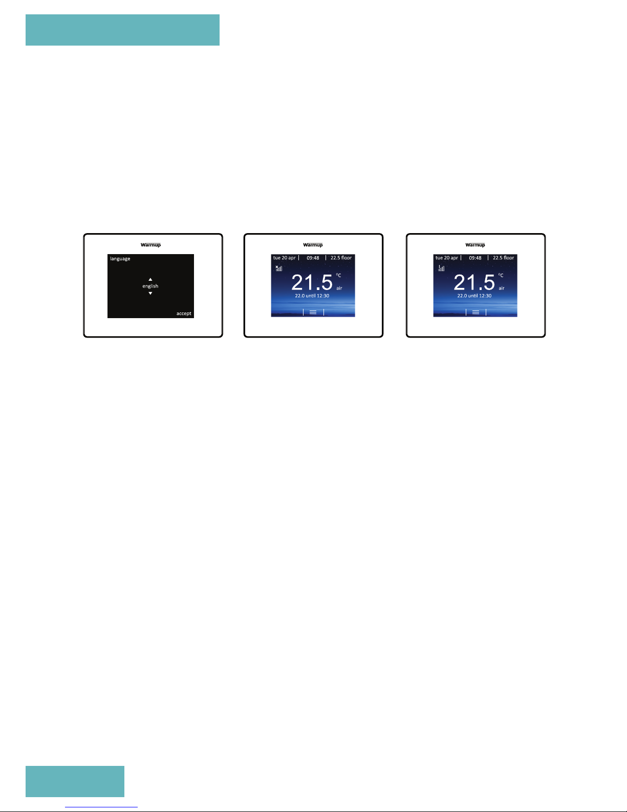
Depending on who has installed your 5iE, you will have one of the
following screens visible. If you have anything other than the
below screens, please press the standby button briey on the
underside of Thermostat Face.
Getting Started
Language
If you have this
screen present, the
Thermostat has not
been connected to a
WiFi network.
Please follow the
on-screen
instructions to
connect it to WiFi
No WiFi
If you have this
screen present, the
Thermostat should
be connected to a
WiFi network.
> settings >
network
No Server
If you have this
screen present, the
Thermostat is
connected to a WiFi
network.
5iE
Step 5 - Getting Started
16
Page 17

App Download
The MyHeating App is available for iOS and Android devices via
the App Store or Google Play. If you have not done so already,
download the MyHeating App to your tablet or smartphone.
Search ‘MyHeating by Warmup’
Device Number
When rst registering and setting up your location on MyHeating,
you will need the device number of the Thermostat. Your installer
should have recorded it below, if not it can be found in the
Thermostat menu:
> settings > advanced settings > about > info
Registration
5iE
Step 6 - Download ‘MyHeating’ App
17
Go to my.warmup.com or
MyHeang to complete setup
Your device number is
ok
Page 18

Below shows the menu structure to follow, when rst registering
with my.warmup.com or the MyHeating app
Registration
5iE
Step 7 - Registering your device
Location
A location needs to be setup before a room can be congured and
the 5iE device registered. Creating a location is user friendly and
easy to follow, it is advised to have details of your current energy
tari and pricing to hand, as these will be required for the energy
monitoring features.
Room
With a location now setup, the next step is to register a room.
When creating a new room, the following options are available to
select:
Location (Select the newly setup location)
Room name (Description, e.g. Upstairs Bedroom)
Room type (Select the room type e.g. General)
Floor type (Select the oor type e.g. Tile/
stone)
Device number (See page 17)
System type (Select ‘Central heating’ for 5iE
setup)
System power (Size of heat source e.g.32kw=32000)
Power source (Energy source e.g. gas)
18
NOTE: For full registration and setup guide, see online at www.warmupsmart.com/installation
Registration
Once the app has been successfully downloaded and device
number recorded you will need to set up your MyWarmup account.
The Thermostat can be registered via the MyHeating app or by
visiting my.warmup.com
Page 19
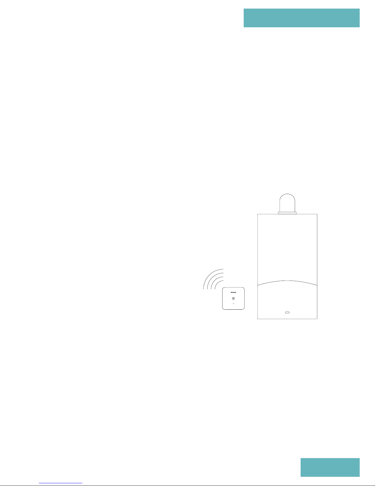
Ok, so you are now all set up and ready to go!
Have you tested your wireless heating control yet?
The 5iE will take approximately two weeks of learning your
routines before it can set a customer schedule just for you. So at
the moment, adjust the temperature as required, once the 5iE
knows your routine, it’ll take over and keep you cosy.
5iE
Step 8 - Overview
Overview
19
Page 20

5iE
Step 9 - Troubleshooting
Troubleshooting
Due to the large number of dierent boiler systems
and wiring plans in use, Warmup cannot guarantee
compatibility with a particular system. Compatible
systems include Combi and System boilers with 230VAC,
volt-free or low voltage input up to 3A. The boiler
manufacturer or manual will be able to conrm if your
boiler is compatible.
Is the 5iE compatible with
this heating system?
How do I pair the system
again?
Thermostat display is
blank
The system type on initial setup should be set to
“Conventional”. If you are using the Thermostat with a
conventional system (central heating) you will not have
a oor sensor installed. Switch the Thermostat to air
mode by pressing menu, settings, heating preference,
control air/amb and switch to air.
Thermostat displays “er1
amb”
If the connection drops the LED on the Boiler Receiver
will ash RED. Remove the Thermostat from the Power
Base and using a device such as a paper clip press the
pairing button as shown on page 13. The light on the
Boiler Receiver will turn o to indicate a successful
connection.
Note: You can manually override the system to get the
heating to work should the wireless connection fail by
pressing the power button on the Boiler Receiver as
shown on page 8.
1. Check that the display/standby brightness is not
on the lowest setting, “0”. To access display/audio
settings rst press the standby button at the bottom
of the Thermostat. Then press menu, settings and
display/audio settings & display brightness.
2. Verify that power is going to the Thermostat. Check
that the Power Base is plugged in.
20
Page 21
5iE
Technical Specications
Technical Specications
Dimensions 86 x 86 x 26.5mm
Power Supply 230V AC, 50Hz
IP Rating IP40
Maximum Relay Load 3A, 250V
Operational Temperature Range 0°C - 50°C
Operational Humidity Range <95% RH
Fuse T1.6A, 250V
Dimensions (Assembled with Thermostat) 120 x 121.4 x 72.5mm
Power Supply 5V DC, 300mA
IP Rating IP30
Operational Temperature Range 0°C - 50°C
Operational Humidity Range <95% RH
Dimensions (Assembled with 4iE face) 90 x 120 x 18mm
Screen size 3.5in
IP Rating IP33
Operational Temperature Range 0°C - 50°C
Operational Humidity Range <95% RH
Boiler Receiver
RF Range (Open Air) Max. 500m
Communication Band 868 MHz
Radio Frequency Standards EN 301 489-1 v1.9.2 / EN 300 220-2
v2.4.1 / EN 62479:2010 /
EN60950-1:2006/A2:2013
Wireless
Thermostat
21
Power Base
Page 22

Contact Us
UK
0345 345 2288
702 & 704 Tudor Estate
Abbey Road
Park Royal
London
NW10 7UW
Warranty
Warmup plc warrants this product, to be free from defects in the workmanship or
materials, under normal use and service, for a period of three (3) years from the date
of purchase by the consumer. If at any time during the warranty period the product is
determined to be defective, Warmup shall repair or replace it, at Warmup’s option. If
the product is defective, please either,
(i) return it, with a bill of sale or other dated proof of purchase, to the place from which
you purchased it, or
(ii) contact Warmup. Warmup will determine whether the product should be returned,
or replaced.
This warranty does not cover removal or re-installation costs, and shall not apply if it
is shown by Warmup that the defect or malfunction was caused by failure to follow the
instruction manuals, incorrect installation or damage which occurred while the product
was in the possession of a consumer.
Warmup’s sole responsibility shall be to repair or replace the product within the terms
stated above.
WARMUP SHALL NOT BE LIABLE FOR ANY LOSS OR DAMAGE OF ANY KIND, INCLUDING ANY
INCIDENTAL OR CONSEQUENTIAL DAMAGES RESULTING, DIRECTLY OR INDIRECTLY, FROM
ANY BREACH OF ANY WARRANTY, EXPRESS OR IMPLIED, OR ANY OTHER FAILURE OF THIS
PRODUCT. THIS WARRANTY IS THE ONLY EXPRESS WARRANTY WARMUP MAKES ON THIS
PRODUCT. THE DURATION OF ANY IMPLIED WARRANTIES, INCLUDING THE WARRANTIES OF
MERCHANTABILITY AND FITNESS FOR A PARTICULAR PURPOSE, IS HEREBY LIMITED TO THE
THREE-YEAR DURATION OF THIS WARRANTY.
This Warranty does not aect your statutory rights.
Lifetime warranty also available. Contact Warmup or visit www.warmup.co.uk for
details
Warmup - Manual - C01 - 5iE - V4.2 0716
 Loading...