

Page 1
WARM SURFACES™
Radiant Floor Heating System
INSTALLATION GUIDE
TWIN WIRE NON-RETURN TYPE
RADIANT HEATING CABLE
86MW
UL FILE #E240867
VER 1.4
Page 2
WARM SURFACES™ INSTALLATION MANUAL VER 1.4
TABLE OF CONTENTS
WELCOME.....................................................................................3
SKILL LEVEL .................................................................................3
CAUTION ......................................................................................4
READ CAREFULLY BEFORE STARTING INSTALLATION .............5
LAYOUT PLAN...............................................................................6
BEFORE INSTALLATION ..............................................................7
INSTALLING WARM SURFACES FLOOR GAUGE………………..……..8
WARNING................................................................................... 11
VERIFICATION – VERY IMPORTANT ........................................ 12
FLOOR SENSOR INSTALLATION ............................................... 13
THERMOSTAT ............................................................................. 13
THERMOSTAT INSTALLATION................................................... 14
IMPORTANT NOTICE ................................................................. 15
TILE TIPS.................................................................................... 15
FLOOR COVERING TECHNIQUE…………………………….…….………………16
DIRECT MORTAR TECHNIQUE .................................................. 17
OPERATING TIPS……………………………………………………………………………18
TABLE 1 CABLES SELECTION AND SPECIFICATION .…………....19
THERMOSTAT TECHNICAL DATA…………………..….…………….………20
~LIMITED WARRANTY AND LIABILITY~ ................................ 21
Product Warranty/Information ................................................ 22
The items you have purchased must include the following:
Warm Surfaces™ Floor Heating Cable
Warm Surfaces™ Floor Gauges
Warm Surfaces™ wall mounted Thermostat including Floor Probe
You will need the following tools and materials to install the Warm Surfaces™
Floor Heating system.
1. Hot glue gun
2. Measuring tape
3. Digital multimeter
4. Megohmmeter
5. Wood chisels
ELECTRICAL REQUIREMENTS
120 V systems require one single pole 15 Amp breaker for each floor cable
240 V systems require one double pole 20 Amp breaker for each floor cable
Electrical wire suitable for the system, 12/2 wire with ground 300Vac
2300 Victoria Avenue, Lachine, Quebec H8S 1Z3 Canada
Tel: 514-634-7100 Fax: 514-634-9868
TOLL FREE : 1-888-552-2257
WarmSurfaces.com
- 2 -
Page 3
WARM SURFACES™ INSTALLATION MANUAL VER 1.4
WELCOME
Thank you for choosing the WARM SURFACES™ floor heating system. This
product has been designed to provide warmth to flooring materials such as
marble, ceramic and porcelain tile, slate, engineered wood, granite and poured or
dimensional stone.
Before using WARM SURFACES™ floor heating system under any floor covering
always refer to the floor-covering manufacturer.
WARM SURFACES™ floor heating systems utilize state-of-the-art heating cables,
hardware and electrical controls for an economical and long lasting floor heating
system.
WARM SURFACES™ is designed for use inside residential , institutional and
commercial buildings.
WARM SURFACES™ floor heating systems are available in cable sets of "120”
volt and “240” volt series products.
WARM SURFACES™ produces a full range of floor heating cable lengths that
may be used in virtually any room and cover virtually any area.
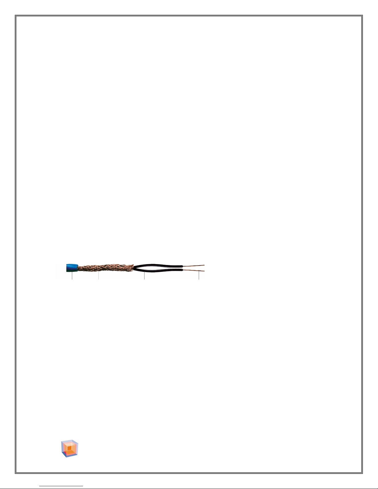
WARM SURFACES™ floor heating cable is manufactured using the highest
quality materials.
NON-RETURN RESISTANCE WIRE
PVC Copper Shield Teflon Resistance
Jacket 0 EMF Insulation Wire
SKILL LEVEL
WARM SURFACES™ recommends that CERTIFIED or QUALIFIED professionals
install any floor heating system. Ask your distributor for a list of recommended
installers.
Electrical inspection is required during and after system installation. Check with
your local electrical inspection department before beginning installation. All
installations must be according to local and national electrical codes.
2300 Victoria Avenue, Lachine, Quebec H8S 1Z3 Canada
Tel: 514-634-7100 Fax: 514-634-9868
TOLL FREE : 1-888-552-2257
WarmSurfaces.com
- 3 -
Page 4
WARM SURFACES™ INSTALLATION MANUAL VER 1.4
CAUTION
DO NOT pull the floor heating wire
tight around the floor gauge.
DO NOT energize a coiled cable.
DO NOT cut or alter the length of the
cable.
Never use the WARM SURFACES™
floor heating cable for applications
other than floor heating.
Never install the heating portion of the
cable in a wall.
Never attempt to repair a damaged
cable. Consult your WARM SURFACES™
Representative.
It is not recommended to extend
the floor heating cable beyond the
room in which it originates.
Never install floor-heating cable in an
area that will be covered by cabinets,
toilets, sinks, bathtubs or shower stalls.
Never combine systems of different
voltages.
Never use spacing less than 2 inches
between floor-heating cables.
Never use floor-heating cable in an
area prone to water infiltration.
Never cut or nick the outer insulation
of the floor heating wire.
Never overlap the floor heating cables.
Overheating will occur.
Never overlap the power leads and the
heating cable. Overheating will occur.
It is not recommended to install the
floor heating cable in a shower stall.
2300 Victoria Avenue, Lachine, Quebec H8S 1Z3 Canada
Tel: 514-634-7100 Fax: 514-634-9868
TOLL FREE : 1-888-552-2257
WarmSurfaces.com
- 4 -
Page 5
WARM SURFACES™ INSTALLATION MANUAL VER 1.4
READ CAREFULLY BEFORE STARTING INSTALLATION
1. Verify your cable selection by measuring and determining the square footage of
the “heated area”. Do not include areas were cabinets, sinks, shower stalls or
closets may be installed.
Note: Since the heating cable cannot be cut and that it’s whole length has to be
covered by the base mortar. The selected cable should always cover an area equal
to or less than that of the heated area excluding the “BUFFER ZONE”. (The buffer
zone is an area of the room where heating can be modified without compromising
the total comfort of the room)
See FIGURE 1.
2. Tampering with the length of the cable (cutting the cable) will result in injury
and/or fire hazard thus voiding the warranty.
3. It is very important that once the layout of the floor heating cable is complete,
we suggest that a drawing or photo be made and kept in your records for future
reference.
4. WARM SURFACES™ floor heating system may be used as a primary source of
heat. Heat generated from the floor is in direct relation with the area of the heated
floor (12 watts /sq ft @ 3” spacing). You should carefully evaluate your heating
needs for your region. A separate source of heat may be needed.
Note: DO NOT pull the floor heating wire tight against the floor gauge, create a 3”
loop.
5. WARM SURFACES™ floor heating system is an “electrical appliance” and it
should be installed in accordance with local and national electrical codes. Qualified
personnel should supervise its installation.
2300 Victoria Avenue, Lachine, Quebec H8S 1Z3 Canada
Tel: 514-634-7100 Fax: 514-634-9868
TOLL FREE : 1-888-552-2257
WarmSurfaces.com
- 5 -
Page 6

WARM SURFACES™ INSTALLATION MANUAL VER 1.4
Buffer Zone
Heated Area
Temperature
Figure 1
LAYOUT PLAN
Before installing the cable, insure that all surfaces on which the heating cable will
lie are free from any sharp objects, i.e. nails, screws, staples, splinters, debris or
other restrictions that may cut or otherwise damage the heating cable.
Refer to HEATED AREA FIGURE 1 for layout details.
Carefully consider the location of the “buffer zone”, (buffer zone is an area of
the room where heating can be modified without compromising the total comfort
of the room) FIGURE 1. Allow sufficient space along walls and cabinets and
around floor drains, toilets and showers.
The heating cable must not overlap under any circumstance. Overlapping will
create a hot spot and will damage the cable.
Probe
2300 Victoria Avenue, Lachine, Quebec H8S 1Z3 Canada
Tel: 514-634-7100 Fax: 514-634-9868
TOLL FREE : 1-888-552-2257
WarmSurfaces.com
- 6 -
Page 7
WARM SURFACES™ INSTALLATION MANUAL VER 1.4
Figure 3
Figure 2
Prope
r knowledge of test
BEFORE INSTALLATION
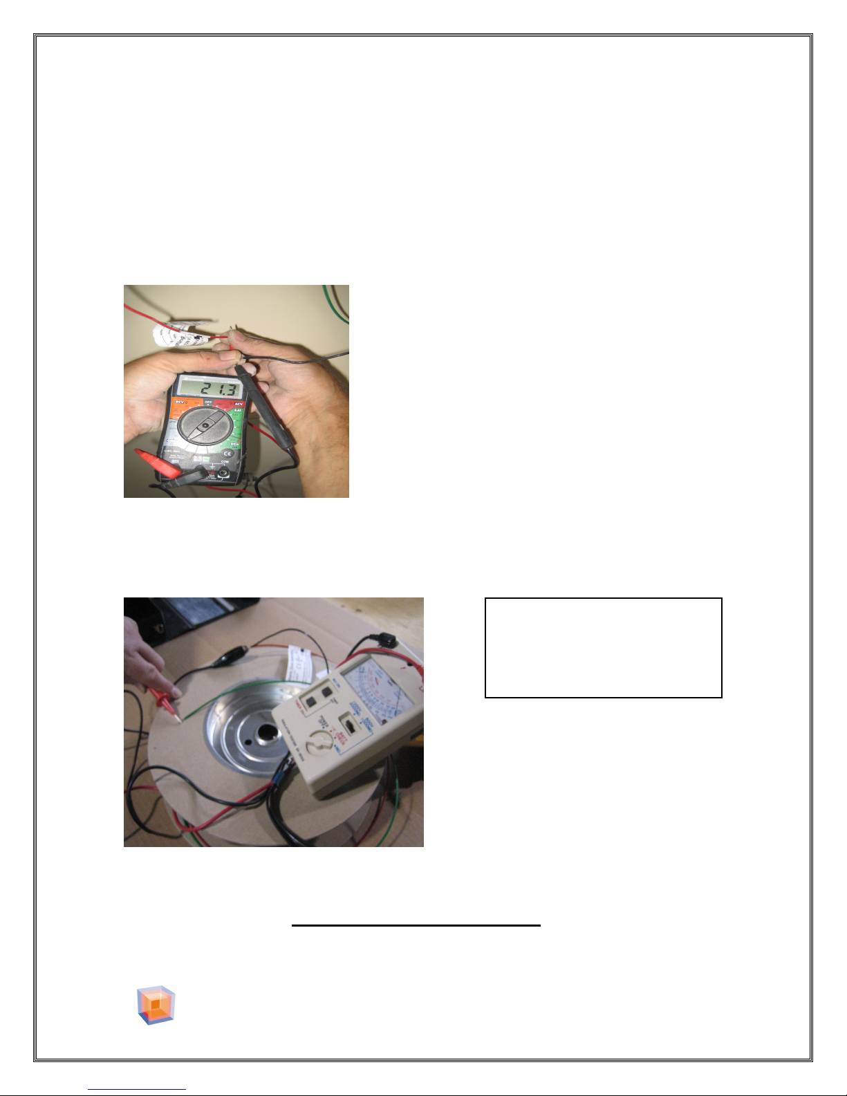
With a digital multimeter measure the resistance of the cable between the two
leads, (Black wire and Red wire or Black wire and White wire) see (FIGURE
2). The resistance of each cable should be within 2 percent of the value in Table
1).The measurement should agree with the value marked on the cold lead of the
cable. Record this value on the warranty page.( page 22 )
If the resistance does not match the resistance
Of the specific cable you have purchased, please
Contact your WARM SURFACES Representative
With a Megohmmeter measure the insulation resistance between the Black wire
and the Green wire. The insulation resistance must not be less than 1000
megohms. Record this value on the warranty page. (page 22 )
equipment is required.
Electrical shock may occur.
If you have measured less than 1000 megohms of resistance between the Black
and Green wires, Do not connect the cable, contact your WARM
SURFACES™ Representative.
2300 Victoria Avenue, Lachine, Quebec H8S 1Z3 Canada
Tel: 514-634-7100 Fax: 514-634-9868
TOLL FREE : 1-888-552-2257
WarmSurfaces.com
- 7 -
Page 8
WARM SURFACES™ INSTALLATION MANUAL VER 1.4
Figure 4
Figure 5
3” Loop
3” Separation from
INSTALLING WARM SURFACES™ FLOOR GAUGE
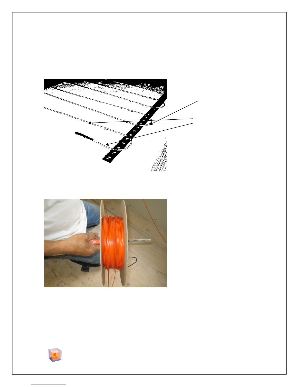
The Warm Surfaces™ Floor Gauge can be stapled or glued to a plywood floor
or sub floor. On concrete surfaces the Floor gauge may be attached by means of
hot melt glue, self-tapping concrete anchors or equivalent.
Do not pull cable tight
wire to wall
It is important to properly uncoil the floor heating cable to prevent twisting.
Support the wire spool so it may turn freely while installing the floor heating wire
Cut a hole in the drywall and the sill plate large enough for three wires from the
floor heating cable and the floor sensor to pass through. This will be normally 1”
diameter.
2300 Victoria Avenue, Lachine, Quebec H8S 1Z3 Canada
Tel: 514-634-7100 Fax: 514-634-9868
TOLL FREE : 1-888-552-2257
WarmSurfaces.com
- 8 -
Page 9
WARM SURFACES™ INSTALLATION MANUAL VER 1.4
Figure 6
3” Separation
Cold Leads
Cold Joint
Floor sensor
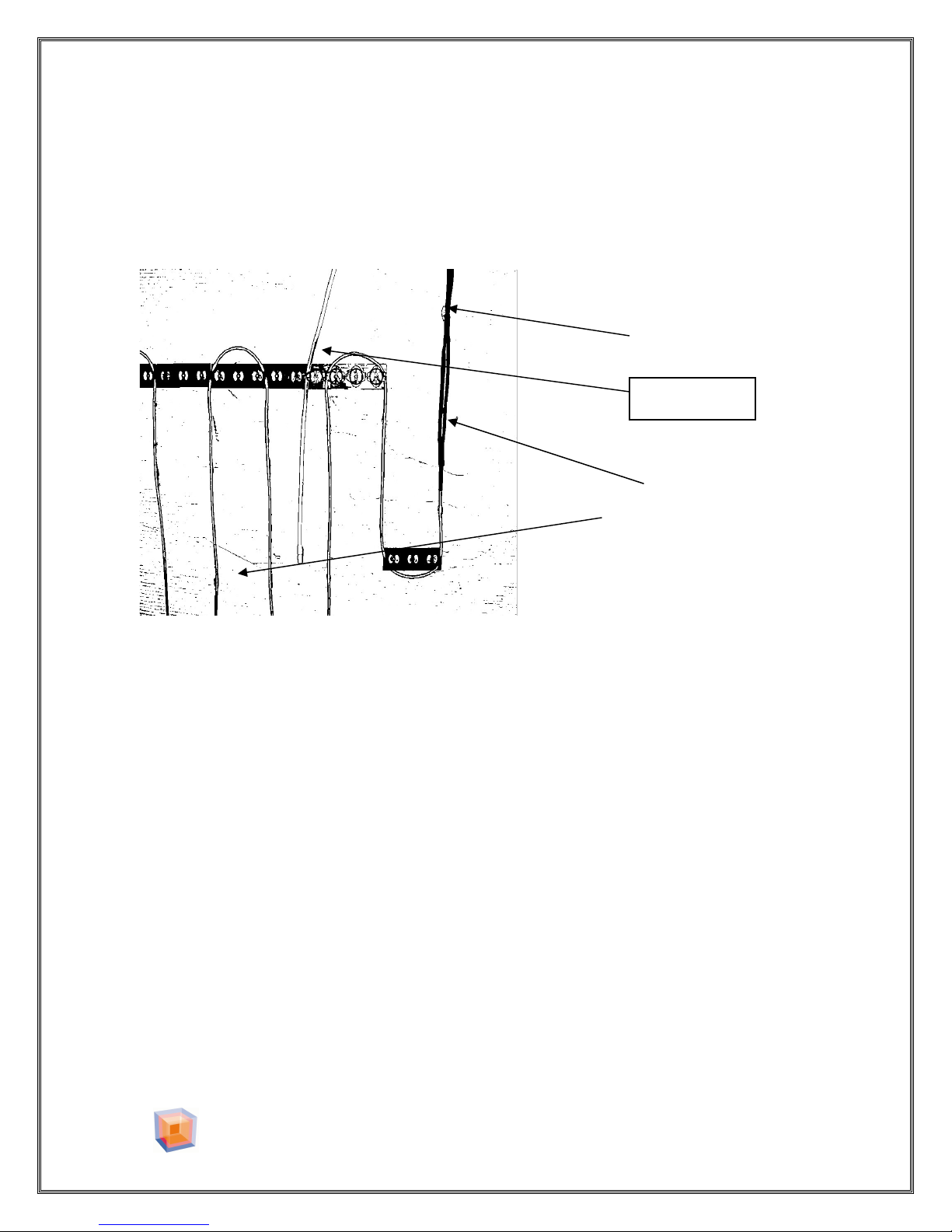
Pull the three cold leads (Green, Black and Red or Green, Black and White
wires) from the main spool through a fish hole in the sill plate using fish cords,
and then into the junction box.
same time.
The cable should be pulled until the factory splice between the
Do not forget to pull the floor sensor at the
heating wire and the lead wire is within 6 to 12 inches of the entry point of the
wall cavity.
Between wire
Mark the splice locations on the floor and temporarily set splice aside. Due to the
larger thickness of the splice and cold lead, remove approximately ¼” of sub floor
material below splice/cold lead areas to eliminate any possible interference with
tile. (For wooden sub floors, use utility knife or chisel; for concrete, use
appropriate chisel.) Remove all debris after this step to avoid cable damage.
2300 Victoria Avenue, Lachine, Quebec H8S 1Z3 Canada
Tel: 514-634-7100 Fax: 514-634-9868
TOLL FREE : 1-888-552-2257
WarmSurfaces.com
- 9 -
Page 10
WARM SURFACES™ INSTALLATION MANUAL VER 1.4
Figure 7
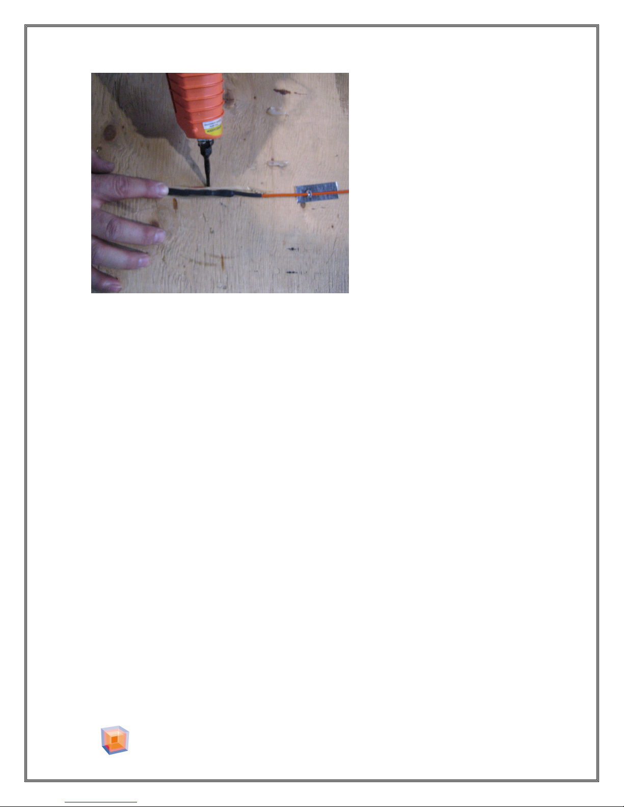
Secure splice and cold lead to floor in recessed areas using Hot melt glue . (Do
not staple the cable). Secure starting point of the heating cable with pieces of
WARM SURFACES FLOOR GAUGE fastened or glued to the floor.
(FIGURE 7)
Place a cardboard box over the cable to protect the heating wire when kneeling or
walking over the heating wire.
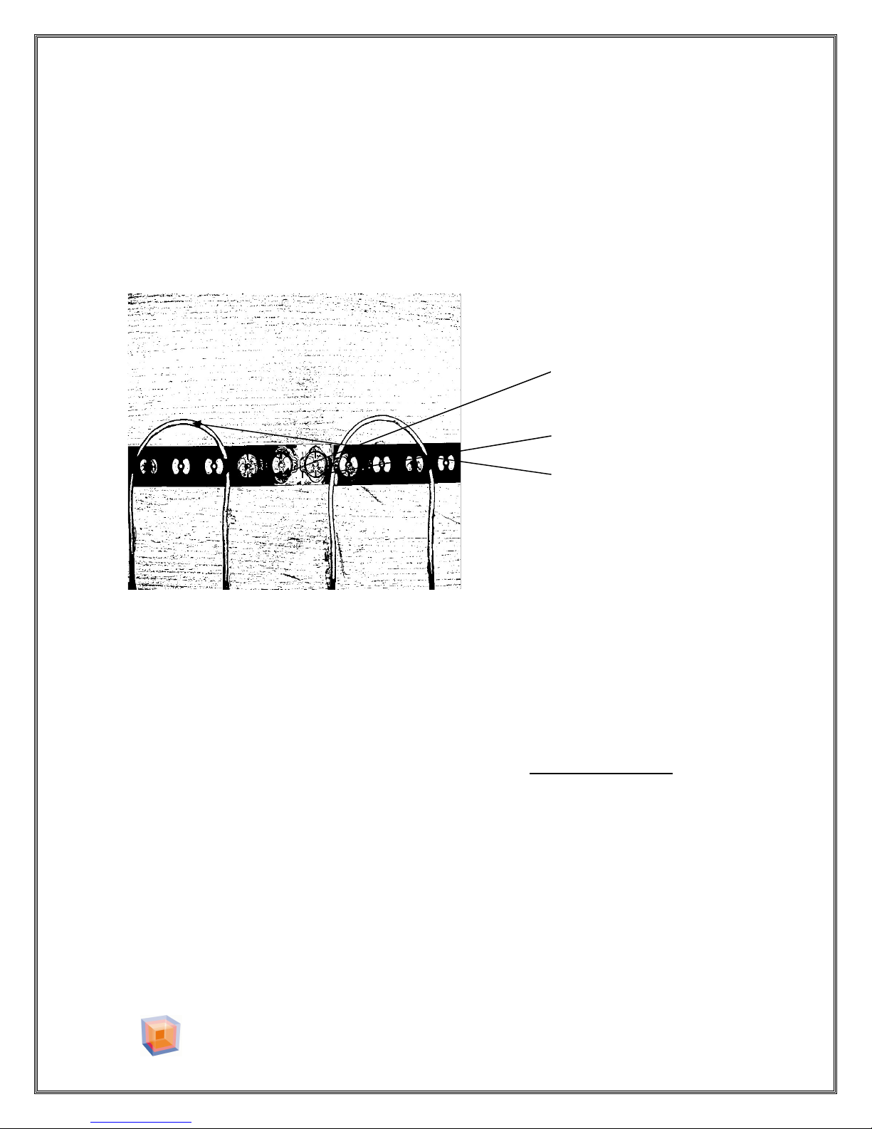
Slide the floor heating cable under the Warm Surfaces™ Floor Gauge tabs at
appropriate intervals and proceed with cable installation . Insure the heating cable
is securely insert at each turn. DO NOT pull the cable tight in the Warm
Surfaces™ Floor Gauge. (Do not staple the cable).
2300 Victoria Avenue, Lachine, Quebec H8S 1Z3 Canada
Tel: 514-634-7100 Fax: 514-634-9868
TOLL FREE : 1-888-552-2257
WarmSurfaces.com
- 10 -
Page 11
WARM SURFACES™ INSTALLATION MANUAL VER 1.4
Figure 8
3” Loop
Staple, Screw
WARNING
DO NOT PULL THE FLOOR HEATING CABLE TIGHT AGAINST THE TURNS
OF THE WARM SURFACES™ FLOOR GAUGE DURING INSTALLATION.
Always form a 3” loop at each corner on the floor gauge. Refer to Figure
8.
Hot glue may be used.
When you reach the half way ,a RED TAPE MARKS indicate the center length of
the cable, evaluate remaining area.
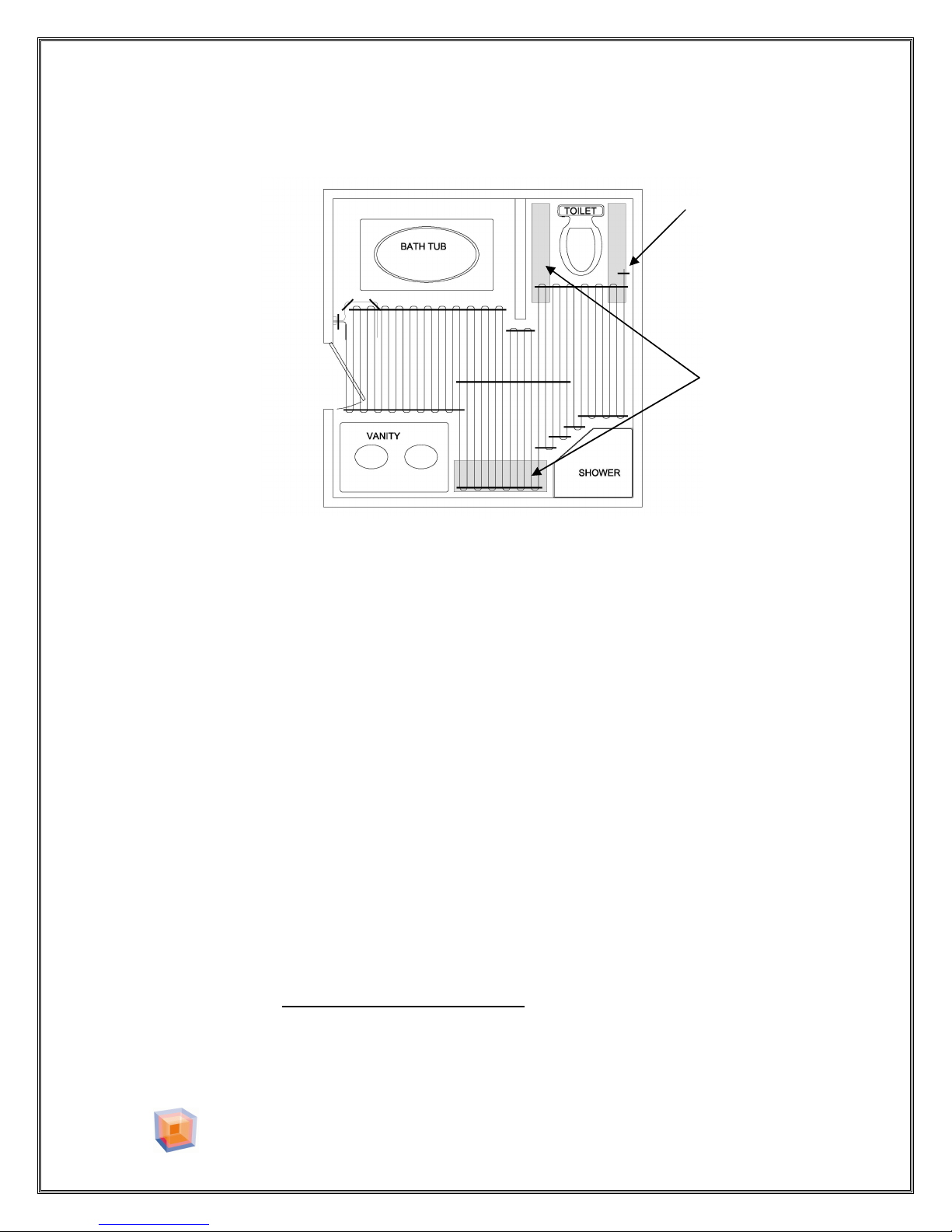
Cable spacing can be adjusted ONLY in the BUFFER ZONE areas.
For cable shortage, consider the “buffer zone” areas and omit placing heating
cable where it would provide little benefit.
For excess cable, spacing can be compressed to a minimum 2-inch pattern in
“buffer zone” areas (FIGURE 9). To adjust cable, gently remove it from the
floor gauge, alter the pattern as required and then re-insert the cable into the floor
gauge.
2300 Victoria Avenue, Lachine, Quebec H8S 1Z3 Canada
Tel: 514-634-7100 Fax: 514-634-9868
TOLL FREE : 1-888-552-2257
WarmSurfaces.com
- 11 -
Page 12
WARM SURFACES™ INSTALLATION MANUAL VER 1.4
Figure 9
Buffer Zone
End of Wire
Layout of excess cable in the buffer zone area
VERIFICATION – VERY IMPORTANT
Before proceeding with covering the floor heating cable with self-leveling cement,
insure damage has not occurred during installation.
Make sure that no wire is overlapping.
With a digital multimeter measure the resistance of the cable between the two
leads, (Black wire and Red wire or Black wire and White wire) see FIGURE 2.
The resistance of each cable should be within 2 percent of the value in Table 1.
Verify that this is the same value as recorded on the warranty sheet.
If the resistance does not match the resistance of the specific cable you have
installed, you should contact your WARM SURFACES™ Representative.
With a Megohmmeter measure the insulation resistance between the Black wire
and the Green wire. The insulation resistance must not be less than 1000
megohms. Verify that this is the same value as recorded on the warranty sheet.
If there is less than 1000 megohms of resistance between the conductor and the
braided shield, Do not connect the cable, you should contact your WARM
SURFACES™ Representative.
2300 Victoria Avenue, Lachine, Quebec H8S 1Z3 Canada
Tel: 514-634-7100 Fax: 514-634-9868
TOLL FREE : 1-888-552-2257
WarmSurfaces.com
- 12 -
Page 13
WARM SURFACES™ INSTALLATION MANUAL VER 1.4
Temperature Probe
Figure 10
Probe wire
FLOOR SENSOR INSTALLATION
Pull the floor sensor cable, through the sill plate hole and into the junction box.
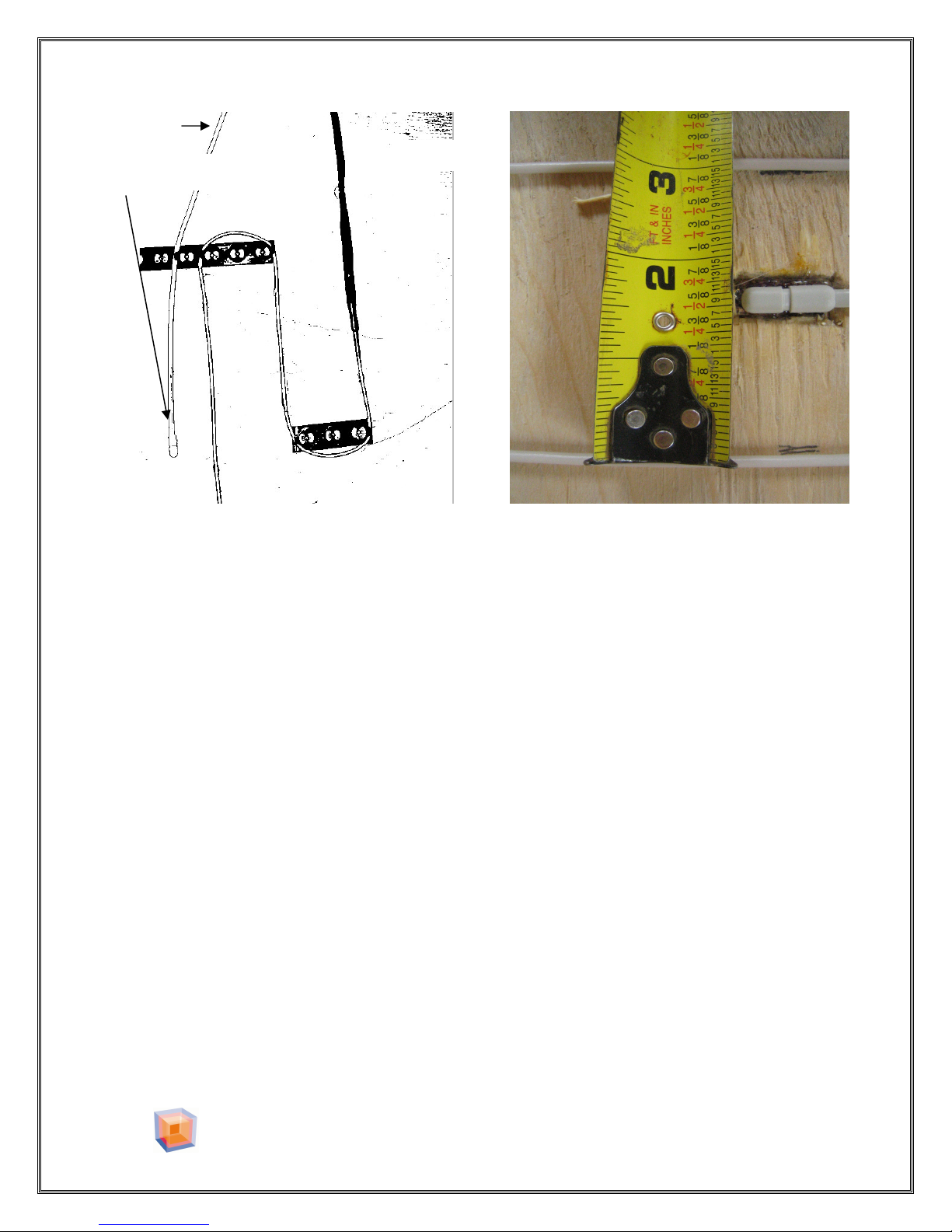
Install the thermostat floor sensor wire at a location where the sensor cable
extends into the heated area a minimum of 2.5 ft from a “cold” wall and is
centered between two adjacent runs of heating cable. Do not locate the
thermostat floor sensor closer than 1” from the heating cable this will cause the
floor to heat unevenly. Do not cross or overlap any other cable, as this will cause
interference with the thermostat control. FIGURE 10.
Also refer to thermostat installation instructions for sensor wire placement.
THERMOSTAT
A standard thermostat, a voltage adjuster or a switch IS NOT SUITABLE to
control the system.
Only a Warm Surfaces™ thermostat sold with the system has a GFCI (Ground
Fault Circuit Interrupter). Use of any other devise will void the warranty.
2300 Victoria Avenue, Lachine, Quebec H8S 1Z3 Canada
Tel: 514-634-7100 Fax: 514-634-9868
TOLL FREE : 1-888-552-2257
WarmSurfaces.com
- 13 -
Page 14
WARM SURFACES™ INSTALLATION MANUAL VER 1.4
Figure 11
Proper knowledge of
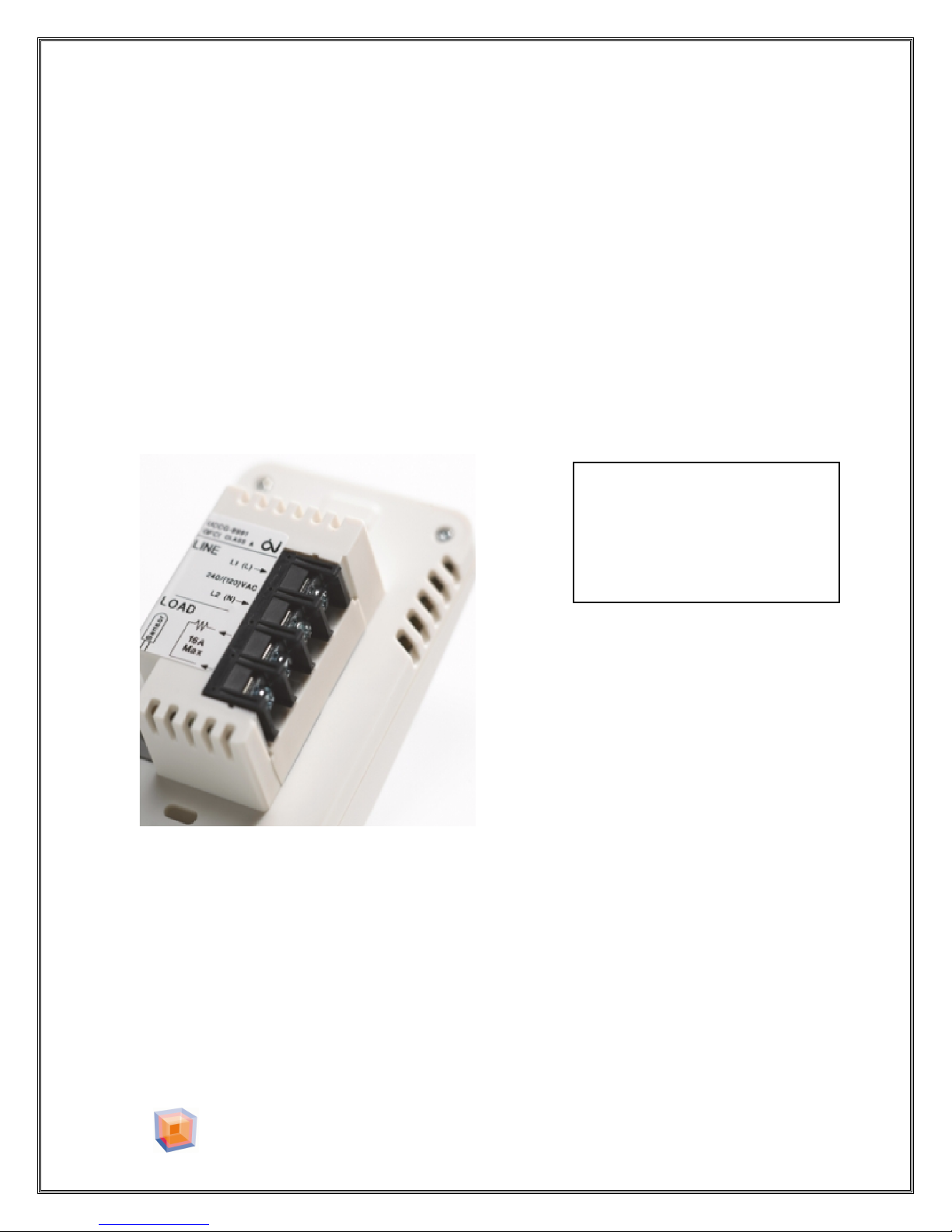
THERMOSTAT INSTALLATION
Ensure the supply branch circuit has been disconnected and de-energized.
Trim excess length of both supply branch circuit and cold lead cables, as
necessary, leaving a minimum of 6" to connect to the thermostat.
Strip 1/4” of insulation off of each conductor.
Connect the Warm Surfaces™ cold lead wire to the thermostat terminals marked
“LOAD”.
Connect the Green wire from the cold lead to the grounding screw in the junction
box.
Connect the supply wires to the thermostat terminals marked “LINE”.
electrical wiring is required.
Electrical shock or fire may
occur.
Installation of all control wiring devices must be according to manufacturer's
instructions. Refer to thermostat installation guide.
The thermostat is an electrical product and must be installed in conformity with
the national and/or the local electrical code.
2300 Victoria Avenue, Lachine, Quebec H8S 1Z3 Canada
Tel: 514-634-7100 Fax: 514-634-9868
TOLL FREE : 1-888-552-2257
WarmSurfaces.com
- 14 -
Page 15
WARM SURFACES™ INSTALLATION MANUAL VER 1.4
IMPORTANT NOTICE
TEST THE COMPLETE SYSTEM PRIOR TO COVERING THE HEATING WIRE.
APPLY POWER TO INSURE PROPER FUNCTIONING OF THERMOSTAT
AND FLOOR HEATING CABLE BEFORE APPLYING A THIN SET OR SELFLEVELING MATERIAL.
SET THE THERMOSTAT ON HIGH TO INSURE CURRENT FLOW. This test
must only by applied for no longer than 5 minutes. Applying power
longer than 5 min. may damage the cable.
Test the system before applying the self-leveling cement or thin set.
Test the system after applying the self-leveling cement or thin set.
Do not fully energize the system until the thin set or self-leveling
material has fully cured. Some products require 20 days to fully cure.
Consult the material manufacture for cure time.
TILE TIPS
Refer to the manufacturer's instructions for cure time. This will insure
that the heat from the cables does not compromise the setting of the
mortar/grout. Cure time is not the same as setting time.
To minimize potential tile cracking, it is important that the sub floor on which the
tile is to be laid is sufficiently rigid. It may be necessary to apply an under-layment
such as backer board and/or mesh and mortar to achieve a solid application
surface to insure the floor is stable, smooth and clean.
Moisture barriers are used to contain water spills in bathrooms. These barriers are
typically a waterproof thin film laid on the floor and any necessary joints will be
sealed with an appropriate waterproof adhesive.
Moisture barriers are to be used in conjunction with WARM SURFACES™ systems
by laying the Warm Surfaces™ Heating Wire on the floor first, covered by a thin
set self-leveling mortar. The moisture barrier is then laid over the thin set and
the flooring completed in the usual manner.
2300 Victoria Avenue, Lachine, Quebec H8S 1Z3 Canada
Tel: 514-634-7100 Fax: 514-634-9868
TOLL FREE : 1-888-552-2257
WarmSurfaces.com
- 15 -
Page 16
WARM SURFACES™ INSTALLATION MANUAL VER 1.4
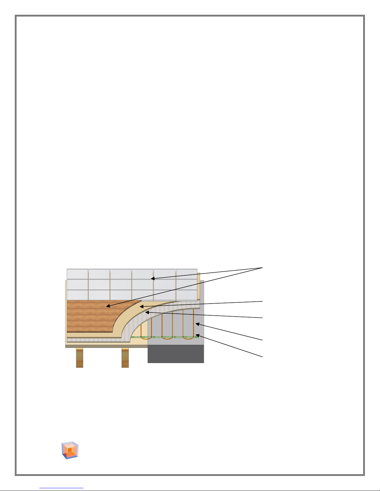
Heating
Cable
Figure 12
Gauge
FLOOR COVERING TECHNIQUE
After the Warm Surfaces™ Floor Heating Cable has been laid and the resistance
measurements have been made you are now ready to set the tiles on the floor.
Verify that power has been removed from the cable. You are now ready to pour
the self-leveling cement.
In this method, the cable is embedded in a "scratch coat" of Thin Set self-
leveling cement, which is allowed to cure prior to setting the tiles. This method
will protect the wire during the laying out of the tiles.
Thin set is applied uniformly over the entire floor area, including any area not
being warmed. Cover the floor with a minimum 1/4” of thin-set. DO NOT
TROWEL THE SELF-LEVELING CEMENT.
After the cement has cured the resistance values are to be measured again and
recorded on the WARRANTY card. Then a thin layer of tile adhesive is applied and
the tile is set.
Before applying power to the system allow the mortar to fully cure. This may
take 3 or 4 weeks. This is not the time allowed to set before applying the tile or
ceramic. Consult the manufacturer of the material used.
Sub Floor: Wood or Concrete
2300 Victoria Avenue, Lachine, Quebec H8S 1Z3 Canada
Tel: 514-634-7100 Fax: 514-634-9868
TOLL FREE : 1-888-552-2257
Floor Covering
Tile or Wood
Toweled
Mortar
Self-leveling
Cement
WarmSurfaces.com
- 16 -
Page 17
WARM SURFACES™ INSTALLATION MANUAL VER 1.4
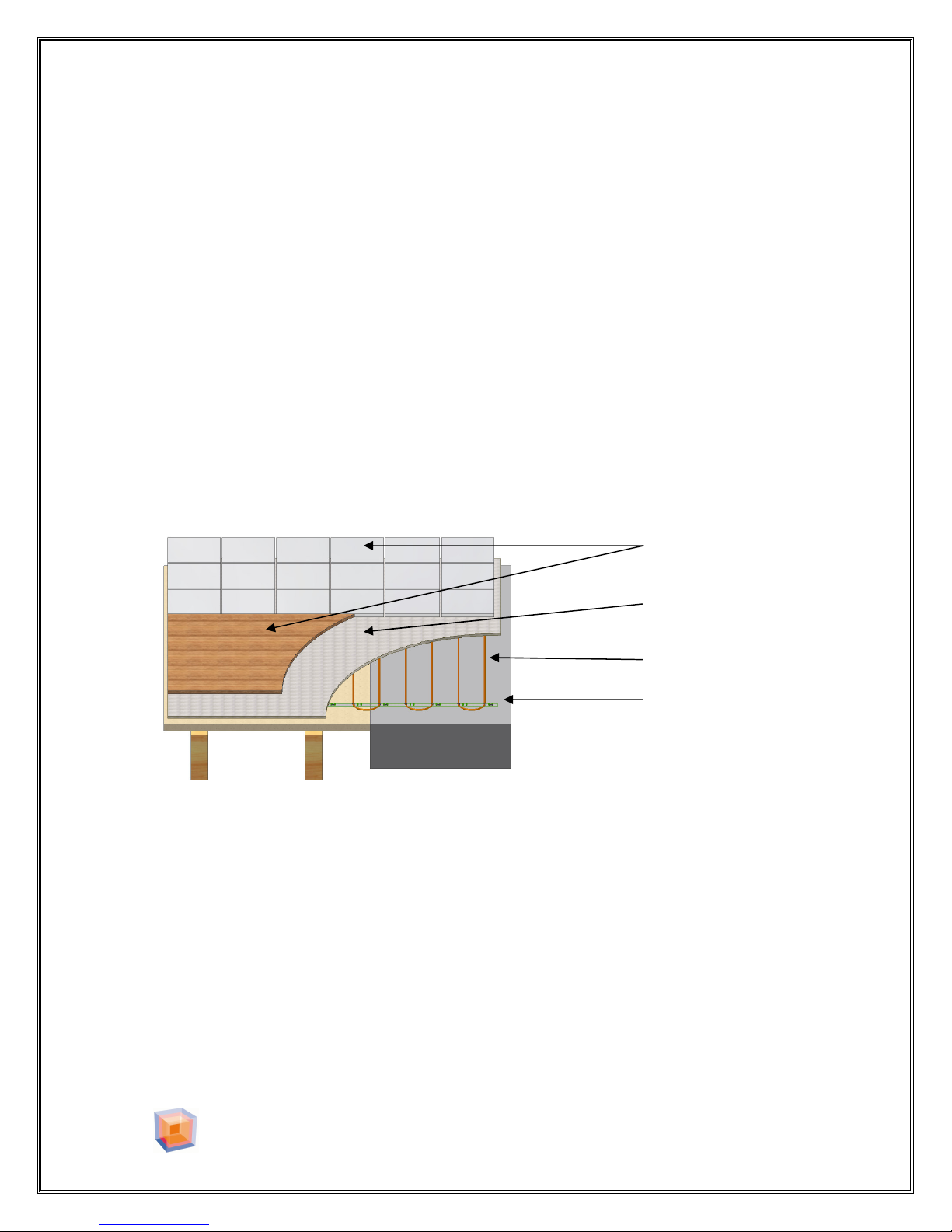
Floor
Co
vering
Mortar
Heating Cable
Figure 13
Floor Gauge
DIRECT MORTAR TECHNIQUE
While it is possible to embed the cable directly in the tile-setting mortar, this
method requires significant tile setting experience to ensure a quality installation.
Several precautions must be followed not to damage the cable.
Always use the flat side of a plastic trowel.
Always trowel in the direction of the cable.
Never place your bucket of mortar on the cable.
Never hit the floor with your trowel.
Never remove excess mortar between tiles with a knife or scrapper.
Use a wet towel or sponge.
Before applying power to the system allow the mortar to fully cure. This may
take 3 or 4 weeks. This is not the time allowed to set before applying the tile or
ceramic. Consult the manufacturer of the mortar.
Sub Floor: Wood or Concrete
Tile or Wood
Trowel
2300 Victoria Avenue, Lachine, Quebec H8S 1Z3 Canada
Tel: 514-634-7100 Fax: 514-634-9868
TOLL FREE : 1-888-552-2257
WarmSurfaces.com
- 17 -
Page 18
WARM SURFACES™ INSTALLATION MANUAL VER 1.4
OPERATING TIPS
DO NOT ENERGIZE THE WARM SURFACES™ FLOOR HEATING CABLE
UNTIL THE CEMENT AND MORTAR HAVE FULLY CURED. THIS MAY TAKE
3 TO 4 WEEKS.
When first energized, the WARM SURFACES™ system may take up to 3 hours to
fully warm your floor. Energy consumption will vary depending on user
preferences and outside temperature, but typically will be about 70% of installed
capacity when the system is energized.
Note: If used as a secondary source of heat in the room, the heat generated by
the WARM SURFACES™ system will be, to some extent, redistributed in the home,
thereby offsetting the heat required from the primary space heating source.
Avoid placing thick mats or rugs on your heated floor, especially in the area where
the floor sensor is located. (Such mats or rugs impede the transfer of heat away
from the cables and result in the floor area beneath them being warmer than
other areas). The use of bath mats and area rugs is acceptable, but they should
be no more than 1/4" thick.
Avoid mats with rubber or vinyl type backing, as these may decompose with heat
and could stain flooring.
Avoid placing floor level furniture (futons, mattresses, etc), which rest directly on
the floor, over heated areas. This will again impede the transfer of heat away from
the cables.
Always allowed air to flow freely under furniture.
2300 Victoria Avenue, Lachine, Quebec H8S 1Z3 Canada
Tel: 514-634-7100 Fax: 514-634-9868
TOLL FREE : 1-888-552-2257
WarmSurfaces.com
- 18 -
Page 19
WARM SURFACES™ INSTALLATION MANUAL VER 1.4
120 VOTS
System Coverage
3”
Model
12W
TW 010120 10
TW 015120 15
TW 020120 20
TW 025120 25
TW 030120 30
TW 035120 35
TW 040120 40
TW 045120 45
TW 057120 57
TW 067120 67
TW 075120 75
TW 085120 85
TW 095120 95
TW 107120 107
240 VOLTS
System
Coverage
3”
Model
12W
TW 020240 20
TW 030240 30
TW 040240 40
TW 050240 50
TW 060240 60
TW 070240 70
TW 080240 80
TW 090240 90
TW 115240 115
TW 135240 135
TW 150240 150
TW 170240 170
TW 190240 190
TW 215240 215
7.6cm
129w/
m2
0.9
1.3
1.8
2.25
2.7
3.2
3.6
4
5.1
6
6.8
7.7
8.6
9.6
7.6cm
129w/
m2
1.8
2.7
3.6
4.5
5.4
6.3
7.2
8.1
10.4
12.2
13.5
15.3
17.1
19.4
&spacing
Resistance
10cm
4”
9W
97w
/m2
Total
WATTAGE Amp.
Total
ohms Length
13 1.2 120 1 122 40
19 1.8 180 1.5 62 60
26 2.4 240 2 60 80
33 3 300 2.5 47 100
40 3.6 360 3 37 120
46 4.1 420 3.6 35 140
52 4.8 480 4 30 160
60 5.4 540 4.5 26 180
75 6.8 684 5.7 21 230
87 7.8 804 6.7 17 270
98 8.8 900 7.5 16 300
110 10 1020 8.5 15 340
125 11.3
140 12.6
&spacing
1140 9.5 12 380
1284 11 11 430
Resistance
10cm
4”
9W
97w
/m2
Total
WATTAGE Amp.
Total
ohms Length
26 2.4 240 1 243 80
39 3.6 360 1.5 124 120
52 4.8 480 2 120 160
65 6 600 2.5 95 200
80 7.2 720 3.1 75 240
90 8.1 840 3.5 70 280
105 9.5 960 4 60 320
117 10.5
150 13.5
175 16.2
1080 4.5 53 360
1380 5.7 43 460
1620 6.8 35 540
195 18 1800 7.5 32 600
220 20.3
2040 8.5 30 680
245 22 2280 9.5 25 760
280 25.2
2580 11 22 860
2300 Victoria Avenue, Lachine, Quebec H8S 1Z3 Canada
Tel: 514-634-7100 Fax: 514-634-9868
TOLL FREE : 1-888-552-2257
WarmSurfaces.com
- 19 -
Page 20
WARM SURFACES™ INSTALLATION MANUAL VER 1.4
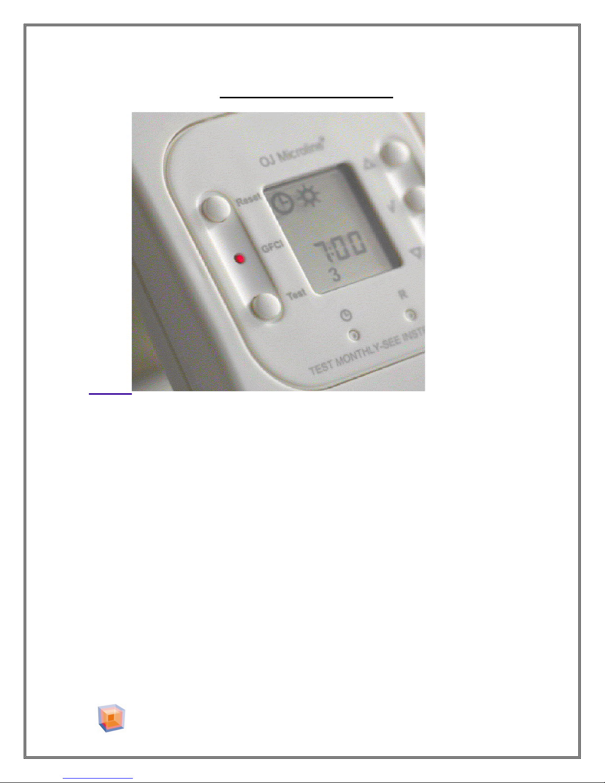
THERMOSTAT TECHNICAL DATA
1. SUPPLY : 120/240V AC 50/60 Hz
2. LOAD : 16A MAXIMUM (resistive load )
3. POWER : 1,920 WATTS at 120V AC
3,840 WATTS at 240V AC
4. GFCI : CLASS A (5mA trip level )
FOR MORE DETAILS ABOUT THE THERMOSTAT, PLEASE CONSULT THE
**USER MANUEL**
2300 Victoria Avenue, Lachine, Quebec H8S 1Z3 Canada
Tel: 514-634-7100 Fax: 514-634-9868
TOLL FREE : 1-888-552-2257
WarmSurfaces.com
- 20 -
Page 21
WARM SURFACES™ INSTALLATION MANUAL VER 1.4
~LIMITED WARRANTY AND LIABILITY~
Cable warrants to the original purchaser only, that if there are any defects in material or
workmanship in any WARM SURFACES™ cable during the first twenty-five (25) years
after the date of its purchase, we will refund the purchase price of the cable, not including
any labor or other installation costs.
Our obligation to refund the purchase price described above is conditional upon (a) the
installation of your cable conforming to the specifications set forth in our installation guide
and (b) the cable not having been damaged by mechanical or electrical activities unrelated
to the operation of the cable.
A refund of your purchase price as described above shall be your sole and exclusive
remedy for a breach of this warranty. This limited warranty does not cover any costs
relating to the repair or replacement of any cable.
K&L Cable. assumes no responsibility under this warranty for any damage to the product
caused by any trades people, or visitor on the job site, or damage caused as a result of post
installation work.
We shall not be liable for any incidental, special or consequential damages as a result of
any breach of this warranty or otherwise, whether or not caused by negligence. Some states
do not allow the exclusion or limitation of incidental or consequential damages, so the
above limitation or exclusion may not apply to you.
No affirmation of fact or promise made by us, by words or action, shall constitute a
warranty. Any implied warranty of merchantability or fitness for particular purpose that
may arise in connection with the sale of this product shall be limited in duration to twentyfive (25) years from the date of purchase. We disclaim all other implied warranties, unless
we are prohibited by law from doing so, in which case all such implied warranties shall
expire at the earliest time permitted by applicable law. Some states do not allow limitations
on how long an implied warranty lasts, so the above limitation may not apply to you. If the
repair of the product is not feasible, K&L Cable will replace the Product or refund the
original cost of the Product.
To obtain a refund under this warranty, please send a description of the defect and proof of
purchase, postage paid, to WARM SURFACES™ at the address noted herein.
@2006 WARM SURFACES™.
2300 Victoria Avenue, Lachine, Quebec H8S 1Z3 Canada
Tel: 514-634-7100 Fax: 514-634-9868
TOLL FREE : 1-888-552-2257
WarmSurfaces.com
- 21 -
Page 22
WARM SURFACES™ INSTALLATION MANUAL VER 1.4
Product Warranty/Information
Keep the original for your record.
Heating Wire type: ___TW__________________
Resistance Measurement
Factory measurement: _______________________
------------------------------------- Cut here-------------------------------------
Heating Wire type: ___TW___________________________________________
Name: _____________________________________________________________
Address: ___________________________________________________________
___________________________________________________________________
___________________________________________________________________
City: _______________________________________________________________
State /Province: _____________________________________________________
Zip/Postal Code: _____________________________________________________
Date of Purchase: ____________________________________________________
Purchased from: _____________________________________________________
Location: ___________________________________________________________
Resistance Measurement
Before breaking the seal :_______________
After installation: ___________________
After cement: __________________
Insulation Resistance Measurement
Before breaking the seal : _______________
After installation: ___________________
After cement: __________________
Type of room
Kitchen ___ Bathroom ___ Rec. Room ___ Other Specify: ________________
WARRANTY IS NOT VALID UNLESS THE WARRANTY FORM IS RETURNED
MAIL , FAX OR E-MAIL TO :
WARM SURFACES
2300 Victoria Avenue, Lachine, Quebec H8S 1Z3 Canada
Tel: 514-634-7100 Fax: 514-634-9868
TOLL FREE : 1-888-552-2257
WarmSurfaces.com
- 22 -
 Loading...