

WARM SURFACES TW 03012, TW 01512, TW 02012, TW 02512, TW 03512 Installation Manual
...
WARM SURFACES™
Radiant Floor Heating System
INSTALLATION GUIDE
TWIN WIRE NON-RETURN TYPE
RADIANT HEATING CABLE
86MW
UL FILE #E240867
VER 1.4
WARM SURFACES™ INSTALLATION MANUAL VER 1.4
TABLE OF CONTENTS
WELCOME.....................................................................................3
SKILL LEVEL .................................................................................3
CAUTION ......................................................................................4
READ CAREFULLY BEFORE STARTING INSTALLATION .............5
LAYOUT PLAN...............................................................................6
BEFORE INSTALLATION ..............................................................7
INSTALLING WARM SURFACES FLOOR GAUGE………………..……..8
WARNING................................................................................... 11
VERIFICATION – VERY IMPORTANT ........................................ 12
FLOOR SENSOR INSTALLATION ............................................... 13
THERMOSTAT ............................................................................. 13
THERMOSTAT INSTALLATION................................................... 14
IMPORTANT NOTICE ................................................................. 15
TILE TIPS.................................................................................... 15
FLOOR COVERING TECHNIQUE…………………………….…….………………16
DIRECT MORTAR TECHNIQUE .................................................. 17
OPERATING TIPS……………………………………………………………………………18
TABLE 1 CABLES SELECTION AND SPECIFICATION .…………....19
THERMOSTAT TECHNICAL DATA…………………..….…………….………20
~LIMITED WARRANTY AND LIABILITY~ ................................ 21
Product Warranty/Information ................................................ 22
The items you have purchased must include the following:
Warm Surfaces™ Floor Heating Cable
Warm Surfaces™ Floor Gauges
Warm Surfaces™ wall mounted Thermostat including Floor Probe
You will need the following tools and materials to install the Warm Surfaces™
Floor Heating system.
1. Hot glue gun
2. Measuring tape
3. Digital multimeter
4. Megohmmeter
5. Wood chisels
ELECTRICAL REQUIREMENTS
120 V systems require one single pole 15 Amp breaker for each floor cable
240 V systems require one double pole 20 Amp breaker for each floor cable
Electrical wire suitable for the system, 12/2 wire with ground 300Vac
2300 Victoria Avenue, Lachine, Quebec H8S 1Z3 Canada
Tel: 514-634-7100 Fax: 514-634-9868
TOLL FREE : 1-888-552-2257
WarmSurfaces.com
- 2 -
WARM SURFACES™ INSTALLATION MANUAL VER 1.4
WELCOME
Thank you for choosing the WARM SURFACES™ floor heating system. This
product has been designed to provide warmth to flooring materials such as
marble, ceramic and porcelain tile, slate, engineered wood, granite and poured or
dimensional stone.
Before using WARM SURFACES™ floor heating system under any floor covering
always refer to the floor-covering manufacturer.
WARM SURFACES™ floor heating systems utilize state-of-the-art heating cables,
hardware and electrical controls for an economical and long lasting floor heating
system.
WARM SURFACES™ is designed for use inside residential , institutional and
commercial buildings.
WARM SURFACES™ floor heating systems are available in cable sets of "120”
volt and “240” volt series products.
WARM SURFACES™ produces a full range of floor heating cable lengths that
may be used in virtually any room and cover virtually any area.
WARM SURFACES™ floor heating cable is manufactured using the highest
quality materials.
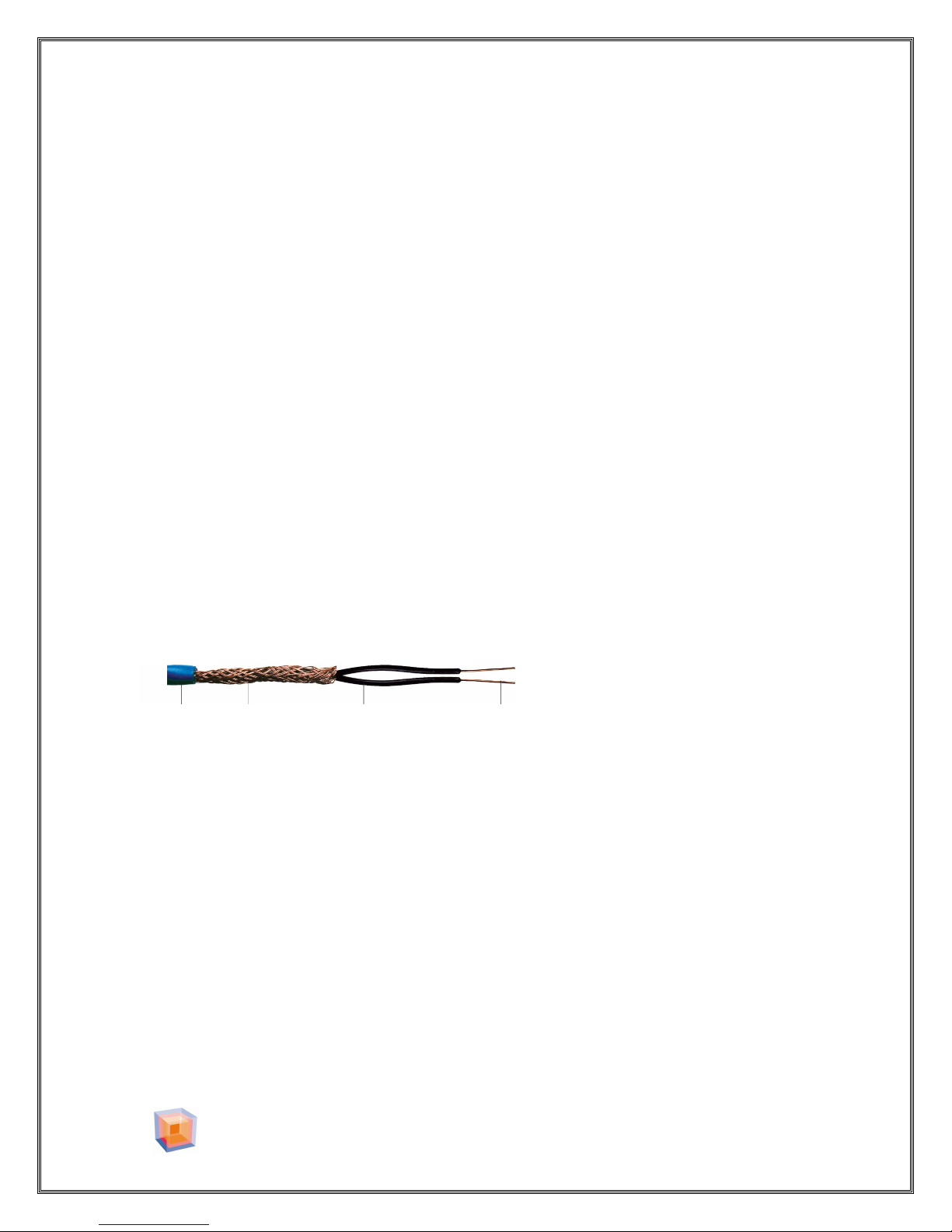
NON-RETURN RESISTANCE WIRE
PVC Copper Shield Teflon Resistance
Jacket 0 EMF Insulation Wire
SKILL LEVEL
WARM SURFACES™ recommends that CERTIFIED or QUALIFIED professionals
install any floor heating system. Ask your distributor for a list of recommended
installers.
Electrical inspection is required during and after system installation. Check with
your local electrical inspection department before beginning installation. All
installations must be according to local and national electrical codes.
2300 Victoria Avenue, Lachine, Quebec H8S 1Z3 Canada
Tel: 514-634-7100 Fax: 514-634-9868
TOLL FREE : 1-888-552-2257
WarmSurfaces.com
- 3 -
WARM SURFACES™ INSTALLATION MANUAL VER 1.4
CAUTION
DO NOT pull the floor heating wire
tight around the floor gauge.
DO NOT energize a coiled cable.
DO NOT cut or alter the length of the
cable.
Never use the WARM SURFACES™
floor heating cable for applications
other than floor heating.
Never install the heating portion of the
cable in a wall.
Never attempt to repair a damaged
cable. Consult your WARM SURFACES™
Representative.
It is not recommended to extend
the floor heating cable beyond the
room in which it originates.
Never install floor-heating cable in an
area that will be covered by cabinets,
toilets, sinks, bathtubs or shower stalls.
Never combine systems of different
voltages.
Never use spacing less than 2 inches
between floor-heating cables.
Never use floor-heating cable in an
area prone to water infiltration.
Never cut or nick the outer insulation
of the floor heating wire.
Never overlap the floor heating cables.
Overheating will occur.
Never overlap the power leads and the
heating cable. Overheating will occur.
It is not recommended to install the
floor heating cable in a shower stall.
2300 Victoria Avenue, Lachine, Quebec H8S 1Z3 Canada
Tel: 514-634-7100 Fax: 514-634-9868
TOLL FREE : 1-888-552-2257
WarmSurfaces.com
- 4 -
WARM SURFACES™ INSTALLATION MANUAL VER 1.4
READ CAREFULLY BEFORE STARTING INSTALLATION
1. Verify your cable selection by measuring and determining the square footage of
the “heated area”. Do not include areas were cabinets, sinks, shower stalls or
closets may be installed.
Note: Since the heating cable cannot be cut and that it’s whole length has to be
covered by the base mortar. The selected cable should always cover an area equal
to or less than that of the heated area excluding the “BUFFER ZONE”. (The buffer
zone is an area of the room where heating can be modified without compromising
the total comfort of the room)
See FIGURE 1.
2. Tampering with the length of the cable (cutting the cable) will result in injury
and/or fire hazard thus voiding the warranty.
3. It is very important that once the layout of the floor heating cable is complete,
we suggest that a drawing or photo be made and kept in your records for future
reference.
4. WARM SURFACES™ floor heating system may be used as a primary source of
heat. Heat generated from the floor is in direct relation with the area of the heated
floor (12 watts /sq ft @ 3” spacing). You should carefully evaluate your heating
needs for your region. A separate source of heat may be needed.
Note: DO NOT pull the floor heating wire tight against the floor gauge, create a 3”
loop.
5. WARM SURFACES™ floor heating system is an “electrical appliance” and it
should be installed in accordance with local and national electrical codes. Qualified
personnel should supervise its installation.
2300 Victoria Avenue, Lachine, Quebec H8S 1Z3 Canada
Tel: 514-634-7100 Fax: 514-634-9868
TOLL FREE : 1-888-552-2257
WarmSurfaces.com
- 5 -

WARM SURFACES™ INSTALLATION MANUAL VER 1.4
Buffer Zone
Heated Area
Temperature
Figure 1
LAYOUT PLAN
Before installing the cable, insure that all surfaces on which the heating cable will
lie are free from any sharp objects, i.e. nails, screws, staples, splinters, debris or
other restrictions that may cut or otherwise damage the heating cable.
Refer to HEATED AREA FIGURE 1 for layout details.
Carefully consider the location of the “buffer zone”, (buffer zone is an area of
the room where heating can be modified without compromising the total comfort
of the room) FIGURE 1. Allow sufficient space along walls and cabinets and
around floor drains, toilets and showers.
The heating cable must not overlap under any circumstance. Overlapping will
create a hot spot and will damage the cable.
Probe
2300 Victoria Avenue, Lachine, Quebec H8S 1Z3 Canada
Tel: 514-634-7100 Fax: 514-634-9868
TOLL FREE : 1-888-552-2257
WarmSurfaces.com
- 6 -
WARM SURFACES™ INSTALLATION MANUAL VER 1.4
Figure 3
Figure 2
Prope
r knowledge of test
BEFORE INSTALLATION
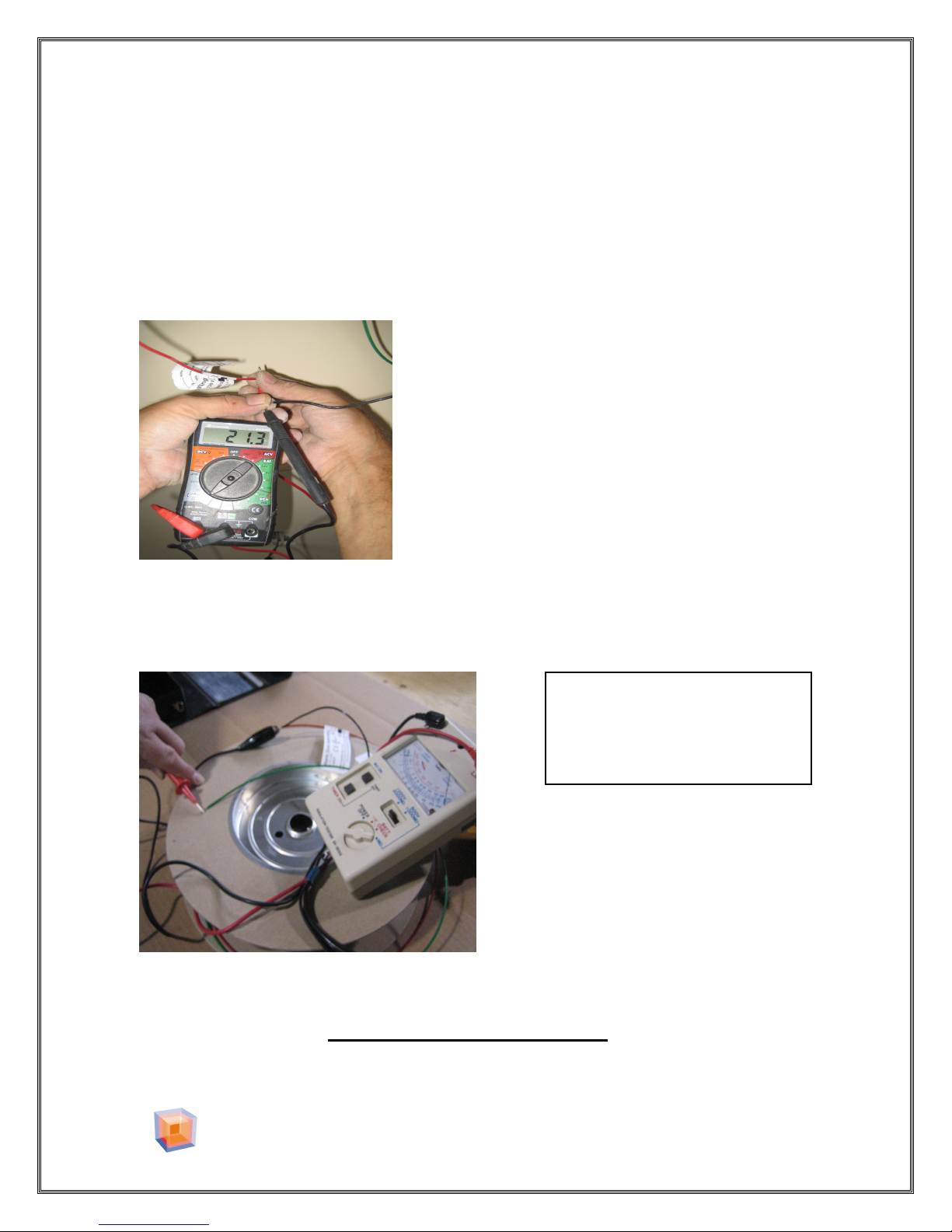
With a digital multimeter measure the resistance of the cable between the two
leads, (Black wire and Red wire or Black wire and White wire) see (FIGURE
2). The resistance of each cable should be within 2 percent of the value in Table
1).The measurement should agree with the value marked on the cold lead of the
cable. Record this value on the warranty page.( page 22 )
If the resistance does not match the resistance
Of the specific cable you have purchased, please
Contact your WARM SURFACES Representative
With a Megohmmeter measure the insulation resistance between the Black wire
and the Green wire. The insulation resistance must not be less than 1000
megohms. Record this value on the warranty page. (page 22 )
equipment is required.
Electrical shock may occur.
If you have measured less than 1000 megohms of resistance between the Black
and Green wires, Do not connect the cable, contact your WARM
SURFACES™ Representative.
2300 Victoria Avenue, Lachine, Quebec H8S 1Z3 Canada
Tel: 514-634-7100 Fax: 514-634-9868
TOLL FREE : 1-888-552-2257
WarmSurfaces.com
- 7 -
 Loading...