

WarmlyYours WSHM24015095, WSHM12015056 Installation Manual
Installation Manual for
Slab Heating Systems
24/7 Installation Support • Lifetime Technical Assistance • Free Design Service • www.WarmlyYours.com • (800) 875-5285

CONTENTS PAGE
1.0 Product Specications ............................................................................. 1
2.0 Selection of the Heating System ................................................................ 2
3.0 Important Instructions before Installing the System................................... 2
4.0 Installation for Slab Heating ....................................................................... 3
4.1 Thermostat & Sensor.......................................................................... 3
4.2 Electrical Provisions for the System ................................................... 3
4.3 Pre-Installation Preparations .............................................................. 4
4.4 Installation for Concrete Embedded Applications .............................. 4
4.5 Operating Tips .................................................................................... 5
4.6 Installation under Concrete ................................................................ 6
4.7 Installation of Slab Heating Mat ......................................................... 6
1.0 PRODUCT SPECIFICATIONS
WarmlyYours Heating Cable is designed for new concrete slab oors. It is well suited
for large areas like basements, garages and additions.
The Heating Cable is comprised of a dual, multistrand heating element with a primary
insulation of Fluoropolymer. The insulated core is then protected with a woven metal
braid and an outer jacket of PVC, EPR or Zero Halogen Polyolen based compound
to make it sturdier and to provide corrosion protection. These cables are terminated
with 20’ (6.1m) long standard cold leads. The hot and cold junction is uniquely
designed to make it durable and exible.
Available in a wide range of lengths and sizes to suit your requirements, the Slab
Heating Mats and Heating Cables are identied as indicated below.
Item Number: AAAA-BBB-CCCC
5.0. Testing the Mats and Cable ....................................................................... 7
5.1 Test One: Total Cable Resistance ....................................................... 7
5.2 Test Two & Three: Insulation Resistance ............................................ 7
6.0 Warranty ..................................................................................................... 7
7.0 Appendix
Appendix A: Slab Heating Mats ............................................................... 8
Appendix B: Slab Heating Cables ............................................................ 8
Appendix C: Cross-section of indoor slab Heating Cable in concrete
(With NO oor covering) ........................................................................... 9
Appendix D: Cross-section of indoor slab Heating Cable in concrete
(With oor covering) ................................................................................. 9
8.0 Troublshooting ............................................................................................ 12
9.0 Warranty ..................................................................................................... 14
Warranty Registration ............................................................................... 15
Ex: Item Number: WSHM-240-0250
• AAAA = WSHM for Slab Heating Mat, WSHC for Slab Heating Cable
• BBB = Operating Voltage available in 120V and 240V
• CCCC = Mat width in ft. (rst two digits) and Mat length in ft. (third and fourth
The available lengths of Slab Heating Mats are shown in Appendix A. The available
lengths of Slab Heating Cables are shown in Appendix B. Both Appendices include
the following attributes for each Item Number.
• Product Type • Watts/Ft for Cable or Watts/Sq Ft for Mats
• Operating Voltage • Amps
• Cable Length
• Mat Width and Length
• Total Ohms
• Total Watts
(product type) (voltage) (width & length = 2’x50’)
digits) for Slab Heating Mat, Cable length in ft. for Slab Heat Cable
1
2.0 SELECTION OF THE HEATING SYSTEM
Wrong
Wrong
Selection of your Heating System will depend on the application. The following can
be taken as a general guide:
INSTALL CHART
Application
Indoor Slab Heating
Watts per Sq.Ft. (per Sq.M.)
- Cable spacing inches (mm)
20 W/ft2 (161 to 215 W/m2)
Recommended spacing 3” to 3.5” (76
to 89mm).
Formula: Area of Application x Multiplier at given cable spacing = Heated Cable
Length required
Example 1 (English): 100 sq.ft of Slab Heating x 4.0 at 3” spacing = 400 feet of
Heated Cable required
Example 2 (Metric): 9.3 sq.m of Slab Heating x 4.0 at 76mm spacing = 122m of
Heated Cable required
Note: For normal plain bare slabs, stained or stamped use 3” spacing. For
application when the slab also has a oor covering like tile or wood, use 5” spacing
for a maximum of 15w/sq ft. to meet code requirements.
Please note the above-indicated values are meant as a general guide. Your values
may vary depending on a number of factors. Please consult your Account Manager
for assistance.
Multiplier at
given spacing
4 at 3” (76mm)
3.5 at 3.5” (89mm)
3 at 4” (102mm)
2.4 at 5” (127mm)
over cable. Duct tape the ends of shovels. Do NOT saw expansion joints, without
having lines marked o clearly with spray paint, where installer has veried that
Heating Cables will not be cut. Do NOT damage Cables with heavy equipment,
machinery or vehicles.
6. Heating Cables should be separated from other heat sources such as luminaries,
and replaces.
7. Do not install the Heating Cable below 5˚ F (-15˚ C) ambient temperature.
8. Minimum bending radius of the Heating Cable shall not be less than 10 times its
diameter.
9. Minimum spacing of Cables is 3” (76 mm) and maximum spacing of Cables is 5”
(127mm).
10. Twin Conductor Heating Cable has a ground braid (metal sheath) to be connected
to ground and 2 conductors which are to be connected to the power supply.
11. Double check the voltage and wattage of the Heating Cable received against
the project specications on your custom installation plan. These are marked on
the CSA label of the product. A qualied electrician should connect the Heating
System.
12. Check the conductor, resistance and insulation resistance of the Heating Cable
before installing and also after installing. Resistance value should match the value
shown in Appendix A and Appendix B. A tolerance of -5% to +10% is allowed.
Insulation resistance must be innite (500 VDC megger meter required to test).
13. Keep high voltage power wires in a separate conduit from the low voltage sensor
wire.
14. Allow sucient drying or curing period of the slab after installing the Heating
System before energizing the Heating System. (7 day minimum)
15. For easy reference, x a label at the power distribution board indicating the
location of the heating units installed.
3.0 IMPORTANT INSTRUCTIONS BEFORE INSTALLING THE SYSTEM
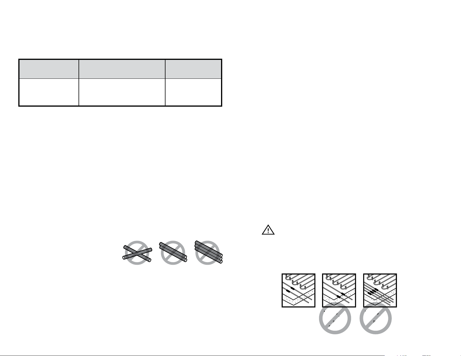
1. Heating Cable must not cross or
overlap itself at any point. Do not
install cable runs any closer than 3”
on center. This could cause the Cable
to overheat, requiring replacement.
2. The Heating Cable length should not
be cut or altered under any circumstances. This may cause over heating resulting in
damage to the Cable.
3. All heated portion (blue) and factory splice must end up buried completely in the
concrete. Ensure none of the heated portion (blue) or the splice (look for heatshrink)
enter into any conduit.
4. The cold lead can be cut /extended with a conventional splice, inside of an
accessible junction box (weatherproof if outdoors).
5. Take precautions to avoid damage to Heating Cable during installation. Do not drive
WARNING
16. The Cable must NOT be shortened or cut in any manner or subjected to strain at
the factory splice joint.
17. NEVER power up Heating Cables prior to being buried in concrete, (even for
testing purposes). This will prevent premature failure of the Heating Cable.
Right
hot/cold joints 3
in (7.6 cm) apart
and 6 in (15 cm)
from slab edge
Wrong
hot/cold joints
installed on
slab edge
Wrong
hot/cold joints
bunched
2
4.0 INSTALLATION FOR INDOOR SLAB HEATING
2’ (61cm)
or
3’ (91cm)
Length 5’ (152cm) min 50’ (1524cm) max
20’ (610cm) Cold Lead
Metal Sheath (Copper/Galvanised Steel/Cladded Steel)
Primary Insulation (Fluoropolymer)
Heating Conductor (Solid/Multistrand)
10"
(251mm)
3"
(8cm)
2’ (61cm)
or
3’ (91cm)
Length 5’ (152cm) min 50’ (1524cm) max
10"
(251mm)
3"
(8cm)
20’ (610cm)
Cold Lead
110V / 230V AC SUPPLY
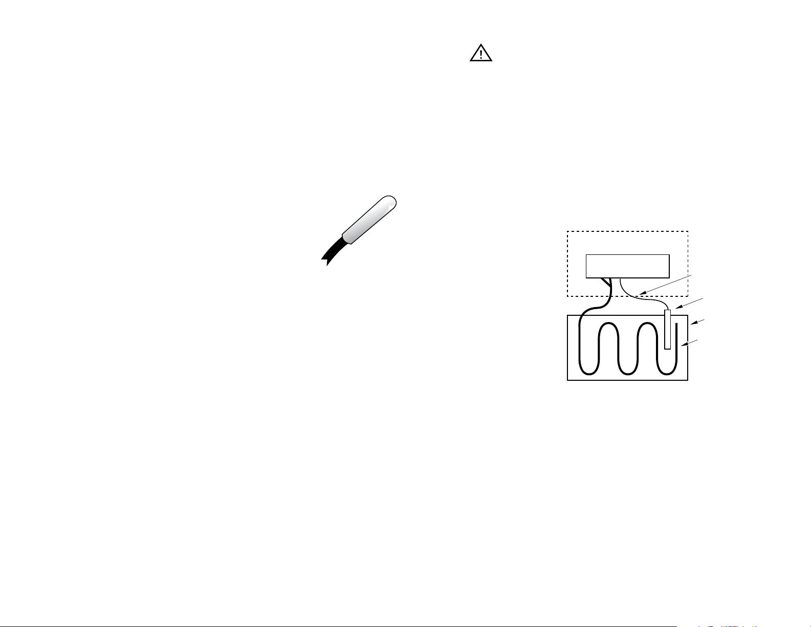
4.1 TEMPERATURE CONTROLLER & SENSOR
We recommend a standard Programmable Thermostat with a temperature sensor
specially designed for control of the Heating System.
The sensor normally comes with a 2 conductor lead wire of 15 feet (4.5m) in
length. Thermostat sensor location shall be centered between two adjacent runs of
Heating Cable within metal pipe or conduit to allow for replacement. Do not position
Thermostat sensor closer than 1.5 inch (38 mm) to Heating Cable. Sensor cable shall
be routed to the Thermostat located in the wall at suitable operating height. Do not
allow any other Heating Cable to overlap with the sensor cable.
WARNING
In case the GFCI in our thermostat trips during normal operation, and cannot be
reset, there is likely a fault in the Cable. No attempt should be made to re-energize
the system. The GFCI must not be bypassed under any circumstances. Consult a
qualied electrician.
DIAGRAM A
The details of the thermostats and installation guidelines are given in
the instruction manual provided with the Thermostat.
Probe type sensor at the
end of 15’ 2 conductor
4.2 ELECTRICAL PROVISIONS FOR THE SYSTEMS
20AWG wire.
The Heating System installation wiring shall be in accordance with the National Electric
Code and any applicable local codes. Controls and accessories recommended for
use along with the Heating Cables are listed below:
• Floor Sensing Temperature controller / Thermostat
• Relay Panel(s) for amp loads greater than 15 amps
• Dedicated Circuit Breaker(s) for all heater circuits. GFCI (5mA trip) or GFPE (30mA
trip) may be required - check local and national code.
• Plastic zip ties, 2” thick polystyrene insulation (provided by installer)
The location of the Thermostat junction box shall be about 4’ (1.2m) high from the
oor for easy access. The oor sensor wire and the Heating Cable cold leads shall be
routed to the Thermostat / power connection box in separate conduits.
If the Heating System has a load below 1,750W at 120V or 3,500W at 240V based
on thermostat power rating, it may be connected directly to an electronic thermostat
as shown in Diagram A which gives a typical scheme of the electrical system. If the
Heating System has a load more than the thermostat power rating, consult your
WarmlyYours Account Manager. (you’ll likely need a relay panel)
120V / 240V VAC SUPPLY
THERMOSTAT
SLAB HEATING SYSTEM
SENSOR WIRE
CAPPED
CONDUIT
FLOOR
HEATING
CABLE
3
4.3 PRE-INSTALLATION PREPARATIONS
2’ (61cm)
or
3’ (91cm)
Length 5’ (152cm) min 50’ (1524cm) max
20’ (610cm) Cold Lead
Polyester Sheath
Metal Sheath (Copper/Galvanised Steel/Cladded Steel)
Primary Insulation (Fluoropolymer)
Heating Conductor (Solid/Multistrand)
10"
(251mm)
20’ (610cm)
Cold Lead
HEATING
CABLE
FLOOR
SENSOR WIRE
CAPPED
CONDUIT
HEATING SYSTEM
THERMOSTAT
110V / 230V AC SUPPLY
1. Review the custom installation plan for the area requiring the Heating System and
verify dimensions listed against your actual eld dimensions to ensure they match.
2. Conrm the location of the power supply box/Thermostat and sensor against the
plan.
3. Select Heating Cable(s) and ensure that the procured Cable is correct according to
the requirements in the following section.
4. Check the Slab Heating Cable in the box visually and make sure that it is not
damaged. Check voltage, wattage, resistance values from the factory test record
and verify that they match the required specications.
5. Check resistance of the conductor and its insulation resistance with a multimeter/
megohmmeter as soon as it is removed from its packing. Resistance value of
the Heating Cable shall match to the value shown in Appendix A or Appendix B.
A tolerance of -5% to +10% is allowed. Insulation resistance should be innite.
Record it on the warranty card located on page 13 of this manual.
6. The Heating Cable is now ready for installation.
4.4 INSTALLATION FOR INDOOR CONCRETE SLAB APPLICATION
1. 2” thick polystyrene insulation (or better) should be installed below slab and around
perimeter edges.
8. Heating Cable should be laid so that the Cables are equally spaced. The distance
between two Heating Cable passes should be according to the spacing calculation
determined by WarmlyYours (3” to 5” range).
9. Route the power leads through a conduit from the oor to the connection box. If
multiple cables are being used, route all power leads through a conduit from the
oor to the connection box in the wall. Ensure hot section and factory splice do
NOT get into the conduit
10. Check the resistance and insulation resistance value after laying out Cables.
Check to see if these values are consistent with the pre-install values. Record
values in the warranty card on page 13.
11. At this point, the concrete can be poured.
12. Pour the concrete and spread evenly on the reinforcement mesh / grid. The
concrete oor or slab thickness shall be about 2” (51 mm) on top of the Heating
Cable. Typical 4” to 6” slabs will have cable located in middle (2” to 3” from
nished surface).
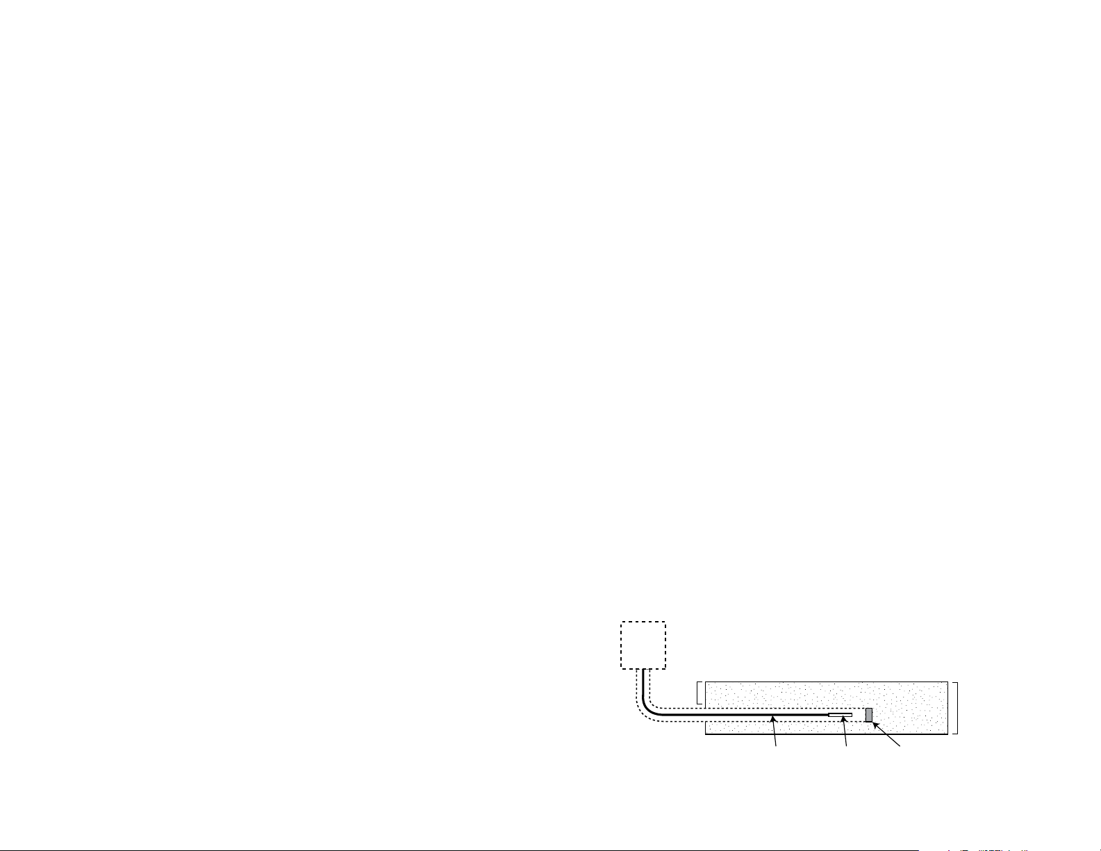
13. Ensure the entire Heating Cable, factory splices and thermostat sensor (in metal
conduit) are embedded in the cement mortar. The choice and application of building
materials should be in accordance with the building material manufacturer’s
instructions. (see diagram B)
14. Ensure the correct curing time for drying of construction materials is followed
before powering ON the Heating Cables (7 day minimum).
2. Reinforcement mesh on the oor or slab should be strong enough to walk on and
not sag or bend.
3. Reinforcement mesh should be properly positioned and supported so that it does
not get disturbed during the concrete pour. Ensure the Heating Cable is on the
reinforcement mesh a minimum of 2” (51mm) below the nished concrete/slab
surface.
4. Surface preparation of the oor is very important. The oor must be completely free
of all debris including all nails, sharp metallic objects, wood and construction debris.
Make absolutely sure that there are no objects on the oor that might damage the
Heating Cable.
5. Start installing Heating Cable from the location of power connection box.
6. Roll out the Heating Cable. Secure it to the reinforcement mesh or grid using plastic
zip ties (supplied by installer).
7. Heating Cable should be laid 3” (76mm) away from the wall perimeter.
15. Check the continuity, resistance and insulation resistance values after the concrete
or mortar is poured. They should be consistent with the values recorded previously.
Record values on the warranty card on page 13 of this manual.
16. Never use 500 VAC megger while personal are standing in, or touching the wet
cement. Wait until personal are out of the wet concrete.
DIAGRAM B
T-Stat
2-3”
4
CONCRETE SLAB
SENSOR WIRE SENSOR
SLAB
4-6”
CAPPED 3/4”
METAL CONDUIT
 Loading...