

Page 1
Floor Heating Application
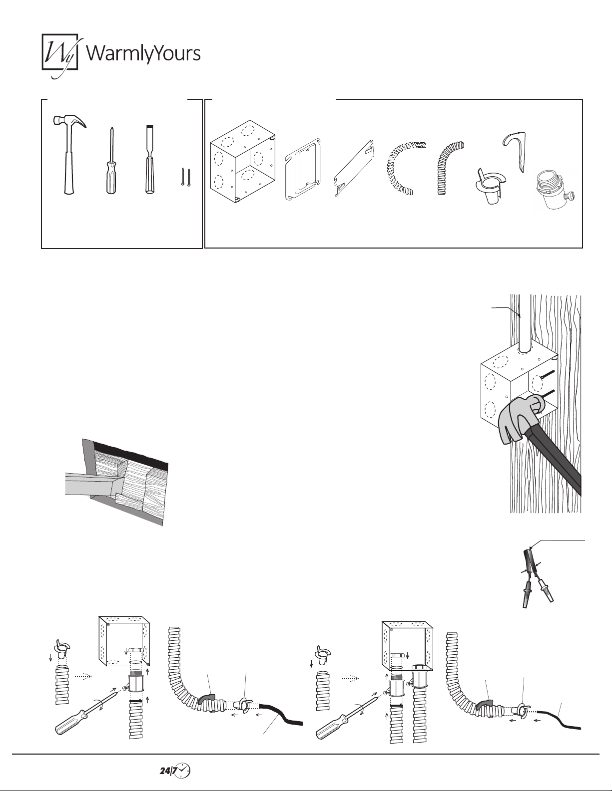
Electrical Install Kit with Conduit Installation
TOOLS REQUIRED (NOT SUPPLIED)
Hammer
Screw
Driver
Wood
Chisel
Nails
KIT ITEMS (ROUGH-IN-KIT-03)
4”x4”
Dual Gang Box
1/2” Single Gang
Mud-Ring
Protector
Plate
6’ Flexible
Conduit
2 pcs.
This kit contains enough conduit for protection of line voltage wires and sensor wires.
PLEASE CONSULT YOUR LOCAL CODE AUTHORITY FOR REQUIREMENTS.
1. Have an electrician supply power to the thermostat box location with a dedicated,
20 Amp 120V or 240V circuit (determined by the voltage of the product ordered),
controlled by a non-GFCI breaker.
2. Place the 4”x4” dual gang box against a stud, approximately 50 inches above the oor.
At this time, it is important to know the thickness of the drywall that will be installed.
The box needs to be mounted so that the raised portion of the single-gang mud-ring that
will be placed onto the box will be ush with the nal wall surface. Once that depth is
determined, hammer two, box-mounting nails through the box into the stud. Break the
tabs/knockouts at the applicable location of the box and insert the power supply wires
and/or conduit into and through the conduit knock-outs.
ENT
Tube
Conduit from
Breaker Box
Drive Strap
Anti-Short
Bushing
4 pcs.
2 pcs.
Set Screw
Connector
2 pcs.
3. The sill plate or bottom plate of the wall may need to be
notched with a wood chisel directly below the location of
the thermostat to allow placement of the conduit for the
coldlead and sensor (if required). There should be a conduit
for the cold lead and a separate conduit for the sensor if the
local code requires low voltage wires be protected by conduit.
Never run the sensor wire in the same conduit as the cold lead!
4. If conduit is required by the local code, install the approved conduit now between the thermostat box and
the notch cut into the bottom plate at the base of the wall. Use approved conduit anchors and bushings to
protect the cold lead wire and sensor wires as they are fed up the wall and into the thermostat box. The
supplied conduit may need to be shortened at this time to t properly. Test the thermostat sensor with a
digital ohm meter as described in the installation manual. If the sensor tests good, run the sensor wire up the
other conduit and into the thermostat box. Install the oor sensor (if applicable) as shown in the instructions.
5.
1.
4.
3.
2.
Drive
Strap
Anti-Short
Bushing
1.
Cold
Lead
1.
2.
4.
3.
2.
5.
Drive
Strap
Black
Anti-Short
Bushing
1.
Sensor Wire
Black
Sensor
Wire
2.
PAGE 1 / 3
Installation Support •(800) 875-5285 • www.WarmlyYours.com
Page 2
Electrical Install Kit with Conduit Installation
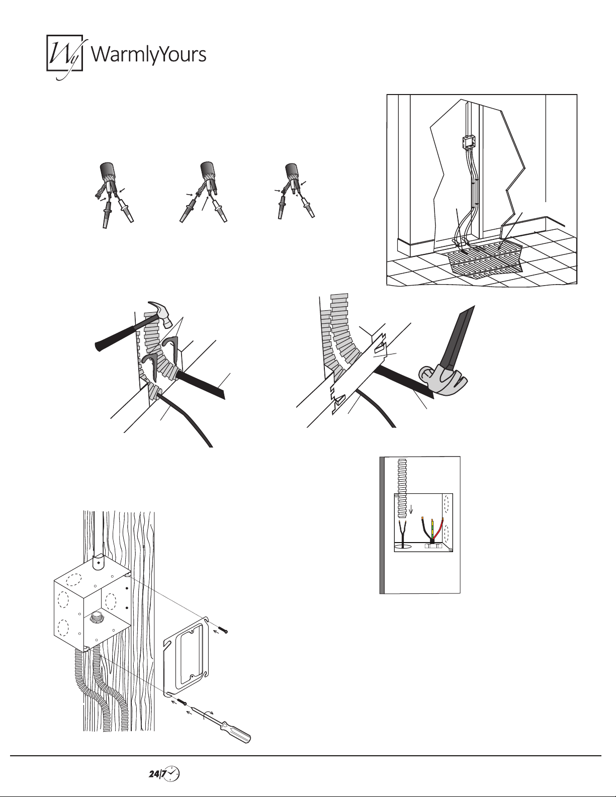
5. Once the electric radiant heating system has been installed, test the system
with a digital ohm meter as described in the installation manual. If the system
tests good, run the cold lead up the conduit and into the thermostat box.
Floor Heating Application
Black
Yellow
or Red
Black
Ground
Yellow
or Red
Ground
6. Once the wires are run up to the thermostat box, install the cable protector
plate so it covers the wires at the bottom plate. This will protect the wires
from stray nails.
Drive Strap
Cold Lead
Floor
Sensor
Floor
Sensor
6/17/99
Protector
Plate
SENSOR
Cold Lead
FLOOR HEATING
SYSTEM
7. Place the smurf/ENT tube over the sensor wire to protect
it from the high voltage wires.
8. Install the single gang mud-ring at this time. Verify that the drywall
being used is 1⁄2” thick. If it isn’t, the mudring included in the kit
will need to be replaced with a locally sourced mud-ring of the
appropriate depth, that corresponds to the thickness of the drywall
being used.
PAGE 2 / 3
Installation Support •(800) 875-5285 • www.WarmlyYours.com
Page 3
Floor Heating Application
Electrical Install Kit with Conduit Installation
Drywall
Fill with Mud
over Mud-Ring
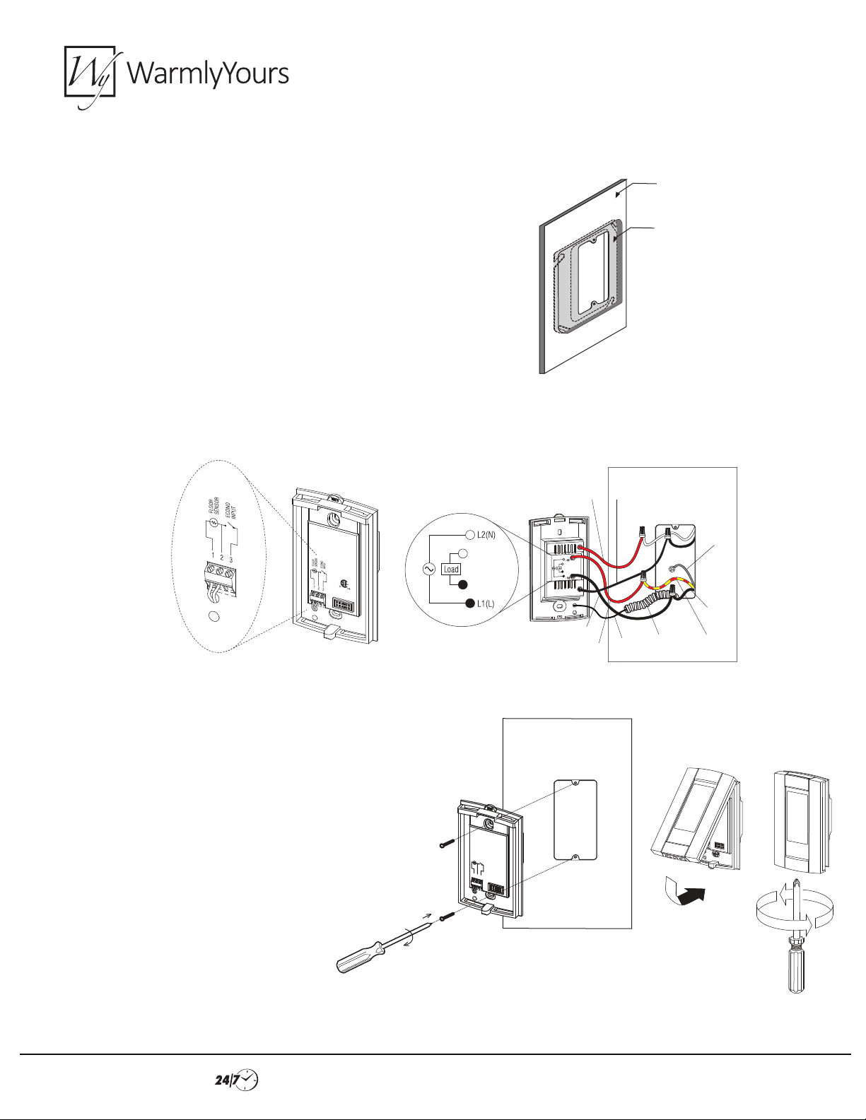
9. When the drywall is installed, the raised portion of the mud-ring
mounted on the square box should be ush with the nished wall's
face and ready for mud to be applied into the gap between the
drywall and the mud-ring.
10. Make connections to line and load wires at the back of the thermostat. Place sensor wires into and through the top hole of the
thermostat’s power base. Attach the sensor wires to the front of the thermostat’s power base.
11. Place the thermostat on the front of the white cover
plate and line up all of the holes. Use the included
screws to attach the power base and white cover plate
to the silver mud-ring. Center and level the thermostat
and then tighten the screws to hold the pieces in place.
Install thermostat’s faceplate onto the power base.
Black
Red
Red
Black
Sensor
Wire
ENT
Tube
Ground
Black
Yellow(120V)
Red(240V)
Installation Support •(800) 875-5285 • www.WarmlyYours.com
PAGE 3 / 3
 Loading...