

WarmlyYours WHCA2080100, WHCA1200043, WHMA1200215, WHCA2400128 Installation Manual
Installation Manual for
Snow Melting Systems
24/7 Installation Support • Free Design Service • www.WarmlyYours.com • (800) 875-5285

Contents
1.0 Product Specications ...................................................................................................... 1
2.0 Selection of the Heating System ......................................................................................... 2
3.0 Important Instructions before Installing the System............................................................ 2
4.0 Installation for Snow Melting .............................................................................................. 3
4.1 Control of Snow Melting System .............................................................................. 3
4.2 Electrical Provisions for the System .......................................................................... 3
4.3 Installation under Asphalt .......................................................................................... 4
4.4 Installation under Concrete ....................................................................................... 5
4.5 Installation in mortar under Pavers ............................................................................ 6
4.6 Installation of Snow Melting Mat ............................................................................... 7
5.0. Testing the Mats and Cable ................................................................................................ 8
5.1 Test One: Insulation Resistance ................................................................................ 8
5.2 Test Two: Total Cable Resistance .............................................................................. 8
6.0 Warranty .............................................................................................................................. 8
7.0 Appendix
Appendix A: WarmlyYours Snow Melting Mats and cable charts .............................................. 9-10
Appendix B: Cross-Section of Snow Melting Cable in Asphalt ................................................. 11
Appendix C: Cross-Section of Snow Melting Cable in Concrete ............................................... 12
Appendix D: Cross-Section of Snow Melting Cable in Mortar Under Pavers ............................ 13
Appendix E: Cross-Section of Snow Melting Cable in Stairs ..................................................... 14
Appendix F: WarmlyYours Snow Melting System Diagram Premium 240V ............................... 15
Appendix G: WarmlyYours Snow Melting System Diagram Premium 277V .............................. 16
Appendix H: WarmlyYours Snow Melting System Diagram Premium 208V............................... 17
Appendix I: WarmlyYours Snow Melting System Diagram SCA-120-SS ................................... 18
Appendix J: WarmlyYours Snow Melting System Diagram Economy 240V .............................. 19
Appendix K: WarmlyYours Snow Melting System Diagram Economy 277V .............................. 20
Appendix L: WarmlyYours Snow Melting System Diagram Economy 208V .............................. 21
Appendix M: WarmlyYours Snow Melting System Diagram Manual 240V................................. 22
Appendix N: WarmlyYours Snow Melting System Diagram Manual 277V ................................. 23
Appendix O: WarmlyYours Snow Melting System Diagram Manual 208V ................................. 24
Appendix P: WarmlyYours Snow Melting System Diagram SCA-DUAL 240V ........................... 25
Appendix Q: WarmlyYours Snow Melting System Diagram SCA-DUAL 277V ........................... 26
Appendix R: WarmlyYours Snow Melting System Diagram SCA-DUAL 208V ........................... 27
Appendix S WarmlyYours Snow Melting System Diagram SCA-DUAL No Relay 240V ............ 28
Appendix T: WarmlyYours Snow Melting System Diagram SCA-DUAL No Relay 208V ............ 29
Appendix U: WarmlyYours Snow Melting System Diagram SCA-DUAL w/Relay 240V ............. 30
Appendix V: WarmlyYours Snow Melting System Diagram SCA-DUAL w/Relay 277V ............. 31
Appendix W: WarmlyYours Snow Melting System Diagram SCA-DUAL w/Relay 208V ............ 32
Appendix X Expansion and Control Joint Cross Section ........................................................... 33
Appendix Y: Junction Box Mounting .......................................................................................... 34
8.0 Troubleshooting ................................................................................................................... 35
1.0 Product Specications
WarmlyYours Heating Cable is designed for outdoor driveways, walkways, stairs and
patios. It is well suited for large areas like driveways.
The Heating Cable is comprised of a dual, multistrand heating element with a primary
insulation of Fluoropolymer. The insulated core is then protected with a woven metal
braid and an outer jacket of PVC, EPR or Zero Halogen Polyolen based compound
to make it sturdier and to provide corrosion protection. These cables are terminated
with 20’ (6.1m) for 120V/240V or 50’ (15.2m) for 208V/277V long standard cold leads.
The hot and cold junction is uniquely designed to make it 100% fool proof.
The Snow Melting Mat is a cable in mat (1.25” x 1.25” mesh openings) construction
which consists of the Heating Cable taped on a Polypropylene (PP) mat. The Heating
Cable is laid in a serpentine fashion so that it is equally spaced and distributed on
the (PP) mat.
Available in a wide range of capacities and sizes to suit your requirements, the Snow
Melting Mats and Heating Cables are identied as indicated below.
Item Number: AAAA-BBB-CCCC
Ex: Item Number: WHMA-240-0250
(product type) (voltage) (width & length = 2’x50’)
• AAAA = WHMA for Snow Melting Mat, WHCA for Snow Melting Cable
• BBB = Operating Voltage available in 120V, 208V, 240V and 277V
• CCCC = Mat width in ft. (rst two digits) and Mat length in ft. (third and fourth
digits) for Snow Melting Mat, Cable length in ft. for Snow Melting Cable
The available sizes of Snow Melting Mats are shown in Appendix A. The available
lengths of Snow Melting Cables are shown in Appendix B. Both Appendices include
the following attributes for each Item Number.
• Product Type
• Operating Voltage
• Cable Length
• Mat Width and Length
• Total Ohms
• Total Watts
• Watts/Ft for Cable or Watts/Sq Ft for Mats
• Amps
9.0 Warranty Registration .......................................................................................................... 37
1
2.0 Selection of the Heating System
Selection of your Heating System will depend on the application. The following can
be taken as a general guide:
Install Chart
6. Do not install the Heating Cable below 5˚ F (-15˚ C) ambient temperature.
7. Minimum bending radius of the Heating Cable shall not be less than 10 times
its diameter.
8. Minimum spacing of Cables is 3” (76 mm) and maximum spacing of Cables is 3.5”
(89 mm). As spacing distance of wire increases, watts per square foot decrease.
Application
Outdoor Snow Melting
Watts per Sq.Ft. (per Sq.M.)
- Cable spacing inches (mm)
45 to 55 W/ft2 (484 to 592 W/m2)
Recommended spacing 3” (76mm).
Multiplier at
given spacing
4.0 at 3” (76mm)
Formula: Area of Application x Multiplier at given cable spacing = Heated Cable
Length required
Example 1 (English): 100 sq.ft of Outdoor Snow Melting x 4.0 at 3” spacing = 400
feet of Heated Cable required
Example 2 (Metric): 9.3 sq.m of Outdoor Snow Melting x 4.0 at 76mm spacing =
122m of Heated Cable required
Please note the above-indicated values are meant as a general guide. Your values
may vary depending on a number of factors. Please consult your Account Manager
for assistance.
3.0 Important Instructions before
Installing the System
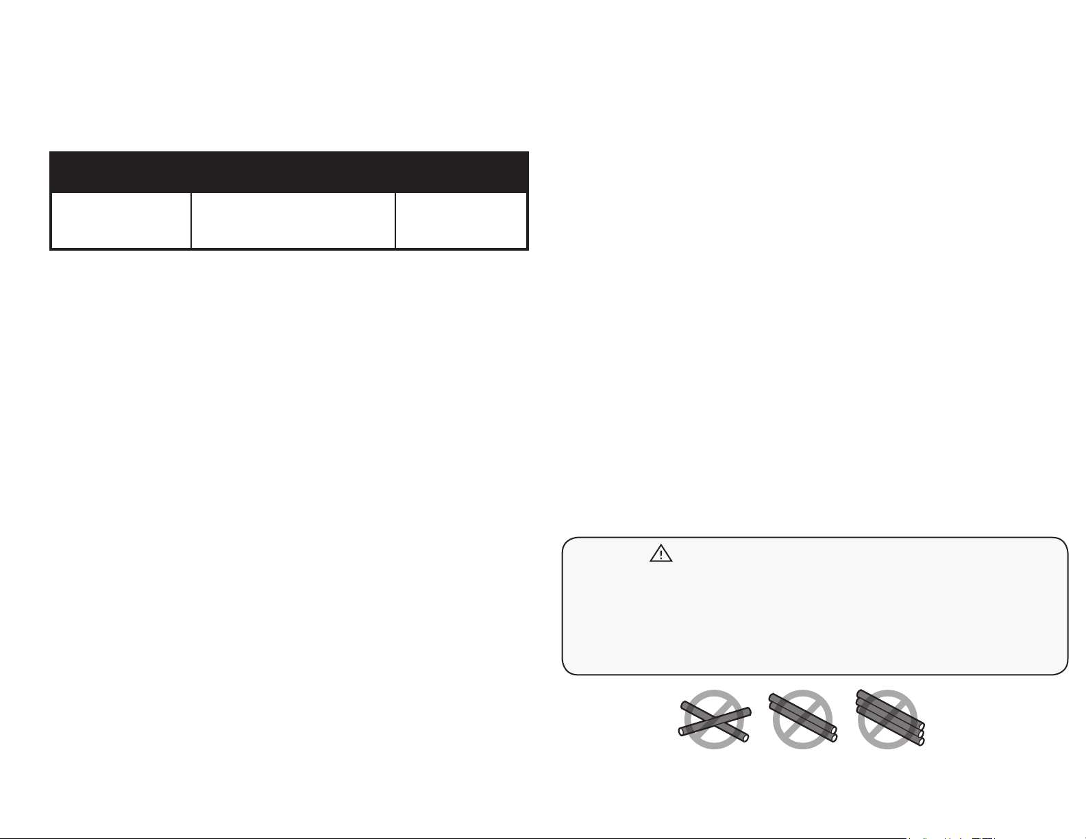
1. Heating Cable must not cross or overlap itself at any point. This could cause the
Cable to overheat, requiring replacement.
2. The Heating Cable length should not be cut or altered under any circumstances. This
may cause over-heating resulting in damage to the Cable.
9. Twin Conductor Heating Cable has a ground braid (metal sheath) to be connected to
ground and 2 conductors which are to be connected to the power supply.
10. Double check the voltage and wattage of the Heating Cable received against the
project specications on your custom installation plan. These are marked on the
packing box of the product. A qualied electrician should connect the Heating
System.
11. A digital Ohm meter and a Megohmmeter (Insulation Tester) will be needed
to properly install the system. Check the continuity, resistance and insulation
resistance of the Heating Cable before installing and also after installing. Resistance
value should match the value shown in Appendix A on page 9 & 10. A tolerance of
-5% to +10% is allowed. Insulation resistance should be innity.
12. Keep high voltage power wires in a separate conduit from low voltage wires.
13. Allow sucient drying or curing period of the concrete / asphalt after installing the
Heating System and before energizing the Heating System.
14. For easy reference, ax a label at the power distribution board indicating the
location of the heating units installed.
15. The National Electric code requires that the heating cables be installed over a base
of at least 2” of substantial masonry or asphalt, and have at least 1.5” of the same
installed over the cable. Our recommendations are based on these NEC standards.
WARNING
16. The Cable must NOT be shortened or cut in any manner or subjected to strain at
the splice joint.
3. The cold lead can be cut or extended with a conventional splice, inside of an
accessible junction box (weatherproof if outdoors).
4. Take precautions to avoid damage to Heating Cable during installation. Do not drive
over cable. Duct tape the ends of shovels. Do NOT saw expansion joints, without
having lines marked o clearly with spray paint, where installer has veried that
Heating Cables will not be cut. Do NOT damage Cables with heavy equipment,
machinery or vehicles. Do not walk on splices, do not bend splices.
5. Heating Cables should be separated from other heat sources such as luminaries
and chimneys.
17. NEVER power-up Heating Cables prior to being buried in concrete, asphalt or
in mortar (even for testing purposes). This will prevent premature failure of the
Heating Cable.
Heating Cable must not cross or overlap itself at any point.
This could cause the Cable to overheat, requiring replacement.
2
Heating Conductor (Solid/Multistrand)
20’ (610cm)
Cold Lead
SENSOR
HEATING
CABLE
FLOOR
HEATING SYSTEM
THERMOSTAT
110V / 230V AC SUPPLY
in (15 cm) apart
and 6 in (15 cm)
from slab edge
installed on
slab edge
bunched
Control joint
Concrete
Heating cable secured to
rebar with plastic tie wraps
Steel bar
3”
3”
Topping 2 in (5.0 cm)
minimum to 3 in (7.5 cm)
maximum thickness
Dimension B must not
exceed 6 in (15 cm)
Dimension A must not
exceed 3 in (7.5 cm)
If dimension C exceeds 3
in(10 cm) an additional run
of cable must be used
B
Wrong
Wrong
C
A
3”
3”
4.0 Installation for Snow Melting
4.1 Control of Snow Melting System
A control suitable for Snow Melting systems with pavement mounted or aerial
mounted sensor should be used for Snow Melting applications, when not using a
Timer.
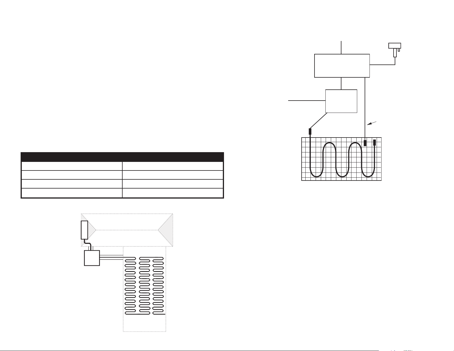
4.2 Electrical Provisions for the Systems
The National Electric Code requires that the heating cables and mats must be
supplied power by a GFEP (30mA) protected circuit.
The Snow Melting system installation wiring shall be in accordance with the National
Electric Code and prevailing local codes.
The snow / moisture sensor cable and the Heating Cable cold leads shall be routed
to the power connection box in separate conduits.
Breaker Size (Amps) Max Design Load (Amps)
40 32
30 24
20 16
15 12
120 VAC
240 VAC
277 VAC
SUPPLY
120 VAC SUPPLY
CONTROL
PANEL
RELAY
PANEL
SLAB TEMP HIGH
LIMIT SENSOR
(IF APPLICABLE)
SNOW MELT MAT AND CABLE
SNOW
SENSOR
RELAY
J-BOX
HOUSE
DRIVEWAY
3

4.3 Installation under Asphalt
1. Ensure that the paving contractor has a solid base of 4” to 8” (102 mm to 203
mm) of crushed rock aggregate tamped down and ready to receive the asphalt.
2. It is extremely important that the paving installer does NOT use any heavy
equipment, machinery, or vehicles over the exposed Heating Cable. Any tracked
mechanical spreaders or dump trucks must be prohibited from running over
exposed Heating Cable.
3. During this process of laying asphalt, installing the heating product, and
laying more asphalt, it is the responsibility of the electrician to use a 500 VDC
megohmmeter and a multi-meter to continuously check the Heating Cables that
are being worked on top of, to ensure they have not been damaged.
4a. The paving installer should lay down the binder / base coat of asphalt and roller it
smooth. The paving installer must decide if this binder coat of asphalt is allowed
to cool before nishing with the top coat of asphalt. This should be coordinated
with the installer of the Heating Cable or Mats. When working on top of hot
asphalt, please consider pre-making “wire mesh heating Mats”. This means
rolling out the reinforcing wire mesh (provided by electrician) and pre-attaching
the Heating Cable to it using wire ties (like rebar wire ties) that will not melt from
the hot asphalt. These “wire mesh heating Mats” could be left in the yard next
to the driveway while the rst binder coat is poured. While the asphalt is still hot,
two people could carry / drag each “wire mesh heating mat” over the hot asphalt,
have it ipped over so that it is wire-side-down / mesh-side-up, and then staked
down to the hot binder coat (stakes provided by electrician).
4b. If the paving installer decides to let the binder / base coat of asphalt cool prior
to nishing with the top coat, then wire mesh is only needed for free-form type
Heating Cable installations. WarmlyYours Snow Melting Mats may be staked
down to the binder coat without using any wire mesh (stakes may only pierce the
black plastic mesh, and should never make direct contact with the Heating Cable
itself). Again, it’s recommended that the Snow Melting Mat be laid down so it
is wire-side-down / mesh-side-up, to help protect it from damage by shovels.
When installing free-form type Heating Cable, stake wire mesh down to the
binder / base coat rst, and then attach the Heating Cable to it using wire ties.
This means it is wire-side-up / mesh-side-down, so extra care must be taken by
the paving installer to avoid damaging the Heating Cables with shovels or rakes
used to spread the top coat of asphalt.
4c. When the binder coat is in place, it is sometimes easier (especially when installing
tire track coverage) to have one person hold the roll of heating mat (wire side
down) as hot asphalt is shoveled over it. as the area is covered the installer
slowly unrolls the product until the remaining area is completed.
5. Once the heater cables are in place, the electrician must route the cold lead(s),
(20’ (6.1m) for 120V/240V or 50’ (15.2m) for 208V and 277V provided per each
Mat/Cable) through rigid metal conduit(s) or other approved means, to get back
to an accessible weatherproof junction box(s). The electrician may supply
junction boxes which can be accessed from above, so the rest of the box is
buried to avoid damage by lawn mowers and/or vehicles. Care must be taken by
the electrician so that none of the heated section of Cable enters the conduit(s).
If a slab-mounted snow sensor will be used, this is the best time for placement.
It should be located in an open area, away from trees or bushes, so that snow
will easily fall directly on it. Separate conduit should be used to protect the low
voltage sensor wire and must NOT be shared with any high voltage cold lead from
the Heating Cables / Mats.
6. Once the Heating Cables and conduits are in place, and are attached by the
methods listed, above the nal top coat of asphalt may be poured. At least 2”
(51mm) of material must cover the Heating Cable. The paving installer will be
required to spread this around evenly with shovels and rakes. Shovels should be
duct taped so the blade ends are less sharp. Again, the topping coat should be
spread manually to avoid use of heavy machinery. The only time it is acceptable
to use a mechanical asphalt spreader would be when it can straddle tire track
coverage used for longer sloped driveways. Tire track coverage allows the
spreader machine to be used without it ever making any direct contact with the
Heating Cables.
7. Once the top coat of asphalt is spread over the Heating Cables evenly with at least
2” (51 mm) thick coverage, it may be rolled over with the steam roller to nish /
atten the driveway. Again, each Heating Cable / Mat must be tested with a multimeter and 500 VDC megohmmeter to verify that they have not been damaged,
and to ensure they will be ready for activation (nal test) after the asphalt has
cured. These values should be recorded on the warranty card on page 35.
4

4.4 Installation under Concrete
1. Ensure that the concrete contractor has installed a solid base of 4” to 8” (102 mm
to 203mm) of crushed rock aggregate base and that it is tamped down and ready
for the concrete pour. The dimensions of the openings in the snow melt rolls are 1
1/4” x 1 1/4”. Use 3/4” or smaller aggregate in concrete when pouring over snow
melt rolls.
2 . It is extremely important that the concrete installer does NOT use any heavy
equipment, machinery, or vehicles over the exposed Heating Cable. During
concrete pours, it is recommended that care be taken to avoid stepping on the
transition portion of cable, where the hot section (green) meets the cold section
(black). This is the location of the factory splice. During this process of installing
the heating product and pouring concrete, it is the responsibility of the electrician
to use a 500 VDC megohmmeter and a multi-meter to keep checking on the
Heating Cables that are currently being worked on top of, to ensure they have not
been damaged, and will be ready for action once the concrete slab has cured.
3. For installations in stairs and ramps that will include hand rails, it is strongly
recommended that the concrete installer pre-sleeve for the posts to avoid any
and all drilling of the concrete. The Heating Cable must be routed around these
sleeves or posts to avoid any direct contact with them. Heating Cables or Mats
must not be allowed to pass thru expansion joint locations. It is recommended
that lines are spray painted on the nished concrete surface by the electrician to
mark o exactly where expansion joints may be located. It is the responsibility of
the electrician and the concrete installer to coordinate their eorts so they avoid
saw-cutting or drilling thru Heating Cables that are no longer visible beneath the
concrete. Following the proposed installation plan from WarmlyYours will help to
ensure this process goes smoothly.
4a. For Two-Pour Installations: The concrete installer pours the rst 2” to 3” (51mm
to 76mm) of concrete. While this rst pour is still wet, rebar or wire-mesh should
be placed on top of the rst pour. The Snow Melting Mats / Cables should be
attached to the rebar / mesh with plastic zip ties, using 3” to 4” (76mm to 102mm)
spacing for free-form type cable. At this time, the electrician must route the cold
lead(s) thru rigid metal conduit(s) or other approved means, to get back to an
accessible weatherproof junction box(es). Care must be taken by the electrician
so that none of the heated section enters any conduit. If a slab-mounted snow
sensor will be used, this is the best time for placement. It should be located in
an open area away from trees or bushes so that snow will easily fall directly on
it. Separate conduit should be used to protect the low voltage sensor wire and
must NOT be shared with any high voltage cold lead from the Heating Cables /
Mats. Once conduits & sensor(s) are placed, the topping pour of concrete can
be nished. Again, the concrete installer(s) must take care not to walk on the
hot-cold splice point, and to avoid damaging the Heating Cables with shovels
and rakes. Taping up the shovel blades helps make them less sharp. Like with
asphalt, it’s recommended that Mats be placed so the mesh faces up, keeping
the wire-side-down to help protect it from shovels.
4b. For Single-Pour Installations: The wire mesh or rebar is rst placed by the
concrete installer or electrician. The electrician then must attach the Heating
Cable to the rebar / mesh with plastic zip ties using 3” to 4” (51mm to 76mm)
spacing for free-form type cable. Then the rebar / mesh must be propped up
with concrete rubble, wire chairs, or brick pavers to the appropriate depth so that
Heating Cable / Mat ends up 2” to 3” (51mm to 76mm) from nished surface and
no deeper. Once rebar / mesh / Heating Cable is all propped up, the electrician
must route the cold leads(s) thru rigid metal conduit(s) or other approved means,
to get back to an accessible weatherproof junction box (es). Care must be taken
so that none of heated section enters any conduit. If a slab-mounted snow
sensor will be used, this is the best time for placement. It should be located in
an open area, away from trees or bushes, so that snow will easily fall directly on
it. Separate conduit should be used to protect the low voltage sensor wire and
must NOT be shared with any high voltage cold lead from the Heating Cables
/ Mats. Once conduits & sensor(s) are placed, the pour of the concrete can be
nished in one step. The concrete installer(s) must take care not to walk on the
hot-cold splice and to avoid damaging the Heating Cables with shovels and
rakes. Mats should be placed mesh facing up, keeping the wire-side-down, to
help protect it from the shovels and rakes.
5. The electrician needs to complete nal testing of all the Heating Cables / Mats
with a multi-meter and a megohmmeter to verify and record that each Heating
Cable has survived the pour of concrete and is ready for action once the concrete
is cured. These values must be recorded on the warranty card on page 35.
5

4.5 Installation under Pavers (Stone or Brick)
1. Ensure that there is a solid base of 4” to 8” (102mm to 203mm) of crushed rock
aggregate base and that it is tamped down and ready to receive the mortar pour.
2. It is extremely important that the paver installer does NOT use any heavy
equipment, machinery, or vehicles over the exposed Heating Cable. During
the paver installation process, it is recommended that care be taken to avoid
stepping on the hot-cold factory splice portion of cable (green meets black).
It is the responsibility of the electrician to use a 500 VDC megohmmeter and
a multi-meter to continuously check on the Heating Cables that are currently
being worked on top of, to ensure they have not been damaged, and will be
ready for action once the mortar pour has cured.
7. The paver installer(s) must take care not to walk on the hot-cold factory splice
and to avoid damaging the Heating Cables with shovels or rakes. Mats should
be placed mesh facing up, keeping the wire-side-down, to help protect them
from shovels.
8. The electrician needs to complete nal testing of all the Heating Cables / Mats
with a multi-meter and a megohmmeter to verify and record that each Heating
Cable has survived the pour of mortar, and is ready for action once the mortar is
cured. These values must be recorded on the warranty card on page 35.
9. If sand or limestone screenings are used instead of mortar, avoid dropping
pavers onto the surface, as doing so may damage the heating cables.
3. For installations in stairs and ramps that will include hand rails, it is strongly
recommended that the paver installer pre-sleeve for the posts to avoid any and
all drilling of the mortar. The Heating Cable must be routed around these sleeves
or posts to avoid any direct contact with them. It is the responsibility of the
electrician and the paver installer to coordinate their eorts so they avoid sawcutting or drilling thru Heating Cables that are no longer visible beneath the
mortar.
4. The paver installer or electrician should place wire mesh (like would be used
in concrete) down on top of the crushed rock aggregate. The mesh should be
staked down rmly to the crushed rock so it remains at. Next, the Heating Cable
or Mats should be attached to the mesh using wire ties to maintain proper depth
and spacing, 3” (76mm) for free-form type Cable. Reference the WarmlyYours
custom installation plan provided with quotation so that this process goes
smoothly.
5. At this time, the electrician must route the cold lead(s) thru rigid metal conduit(s)
or other approved means, to get back to an accessible weatherproof junction
box(es). Care must be taken by the electrician so that none of the heated section
(green) enters any conduit. For this type of application, we recommend using
an aerial mounted snow sensor to avoid having to cut around a circular slab
mounted sensor (this could cause a trip hazard or premature paver crumble).
Once the conduit(s) is in place, the product is ready to receive the mortar pour
or sand, or limestone screenings.
WARNING
1. Brick and Stone Pavers must NOT be any thicker than 2.5” (63.5mm).
2. We do not recommend tire track coverage when using pavers
6. Care must be taken by the paver installer so the mortar covers the Heating Cables
/ Mats and they will not make direct contact with the pavers. We recommend
that at least 1” (25mm) thick mortar is poured over the Heating Cables / Mats,
but no more than 1.5”(38mm). If using sand or limestone screenings, cover to an
uncompacted depth of 1.5” (38mm), leveled to grade.
6
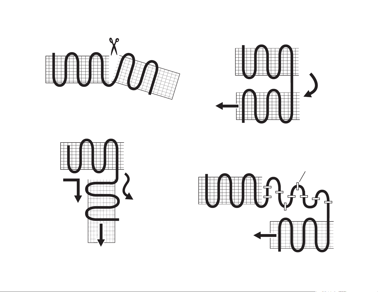
4.6 Installation of Snow Melting Mat
Use scissors to cut the Mat. NEVER cut the Heating Cable
Flip / Turn the Mat
For 90 Degree Turn
For 180 Degree Turn
Turn the Mat
180˚
For other shapes, detach Cable from Mat to required
length and lay only Cable.
Means of attachment may vary
project to project.
90˚
Flip the
Mat Reverse
7

5.0 Testing the Mats and Cable
6.0 Warranty
5.1 Test One: Insulation Resistance
(Megohmmeter Required)
1. Connect one meter clamp to the cold lead (pigtail) inner conductors and the
other meter clamp to the metal cable braided sheath (ground) of the Heating
Cable.
2. Test in accordance with the meter manufacturer’s instructions. Recommended
meter is a 500 VDC megohmmeter.
3. Megohmmeter reading should read innity.
4. Record measured values on the warranty card on page 36. Perform this test
before, during and after installation of the Heating Cables.
5.2 Test Two: Total Cable Resistance
(Multi-Meter Required)
1. Connect one meter clamp to one cold lead (pigtail) inner conductor and the other
meter clamp to the other cold lead (pigtail) inner conductor.
2. Test in accordance with the meter manufacturer’s instructions and record this
ohm value on the warranty card on page 36.
WarmlyYours provides a warranty for the Heating Cables for a period of 10 years
from date of purchase, covering the materials and workmanship under normal
operating conditions.
In case of defective material, WarmlyYours obligation will be limited to the repair or
supply of new material, free of charge to the customer.
The warranty does not cover installations made by unqualied persons or faults
caused by incorrect design by others / misuse / damage caused by others /
damage in transit / incorrect installation and any other subsequent damage that
may occur. Costs related to repair / replacement will be fully chargeable to the
customer if the damage is due to of any of the above reasons.
WarmlyYours is under no circumstances liable for consequential damages or losses
including without limitations the loss or prot arising from any cause whatsoever.
The guarantee is a material warranty only and does not cover eld labor.
The warranty is void if there is any payment default and if data is not lled in on
attached warranty card.
3. Total nominal cable resistance information is found on the CSA label, the bill
of materials and Appendix A, or can be obtained by calling your WarmlyYours
Account Manager. Actual reading should be within -5% - +10% of the cable
resistance.
4. Record measured values on the warranty card on page 36. Perform this test
before, during and after installation of the Heating Cables.
5. Please be sure that you write in the full part number of the Cable or Mat next to
your results.
8

7.0 APPENDIX A:
WARMLYYOURS SNOW MELTING MATS (SUITABLE FOR ASPHALT, CEMENT AND UNDER PAVERS)
Part # Size (ft/m) Voltage Area (ft2/m2) Cable Length (ft/m) Total Ohms Total Watts Watts/ft2 (W/m2) Amps
WHMA-120-0205 2’ x 5’ (0.61 x 1.52m) 120 10.0 (.93m2) 42.77 (13.04m) 28.80 500 50.00 (538W/m2) 4.17
WHMA-120-0305 3’ x 5’ (0.91 x 1.52m) 120 15.0 (1.39m2) 62.78 (19.14m) 19.20 750 50.00 (538W/m2) 6.25
WHMA-120-0210 2’ x 10’ (0.61 x 3.05m) 120 20.0 (1.86m2) 85.54 (26.07m) 14.40 1,000 50.00 (538W/m2) 8.33
WHMA-120-0310 3’ x 10’ (0.91 x 3.05m) 120 30.0 (2.79m2) 125.56 (38.27m) 9.60 1,500 50.00 (538W/m2) 12.50
WHMA-120-0215 2’ x 15’ (0.61 x 4.57m) 120 30.0 (2.79m2) 128.31 (39.11m) 9.60 1,500 50.00 (538W/m2) 12.50
WHMA-120-0315 3’ x 15’ (0.91 x 4.57m) 120 45.0 (4.18m2) 188.34 (57.41m) 6.40 2,250 50.00 (538W/m2) 18.75
WHMA-240-0210 2’ x 10’ (0.61 x 3.05m) 240 20.0 (1.86m2) 85.54 (26.07m) 57.60 1,000 50.00 (538W/m2) 4.17
WHMA-240-0215 2’ x 15’ (0.61 x 4.57m) 240 30.0 (2.79m2) 128.31 (39.11m) 38.40 1,500 50.00 (538W/m2) 6.25
WHMA-240-0220 2’ x 20’ (0.61 x 6.10m) 240 40.0 (3.72m2) 171.08 (52.15m) 28.80 2,000 50.00 (538W/m2) 8.33
WHMA-240-0230 2’ x 30’ (0.61 x 9.14m) 240 60.0 (5.57m2) 256.63 (78.22m) 19.20 3,000 50.00 (538W/m2) 12.50
WHMA-240-0240 2’ x 40’ (0.61 x 12.19m) 240 80.0 (7.43m2) 342.17 (104.29m) 14.40 4,000 50.00 (538W/m2) 16.67
WHMA-240-0250 2’ x 50’ (0.61 x 15.24m) 240 100.0 (9.29m2) 427.71 (130.37m) 11.50 5,000 50.00 (538W/m2) 20.87
WHMA-240-0310 3’ x 10’ (0.91 x 3.05m) 240 30.0 (2.79m2) 125.56 (38.27m) 38.40 1,500 50.00 (538W/m2) 6.25
WHMA-240-0315 3’ x 15’ (0.91 x 4.57m) 240 45.0 (4.18m2) 188.34 (57.41m) 25.60 2,250 50.00 (538W/m2) 9.38
WHMA-240-0320 3’ x 20’ (0.91 x 6.10m) 240 60.0 (5.57m2) 251.12 (76.54m) 19.20 3,000 50.00 (538W/m2) 12.50
WHMA-240-0330 3’ x 30’ (0.91 x 9.14m) 240 90.0 (8.36m2) 376.68 (114.81m) 12.80 4,500 50.00 (538W/m2) 18.75
WARMLYYOURS SNOW MELTING CABLES (SUITABLE FOR ASPHALT, CEMENT AND UNDER PAVERS)
Part # Voltage Cable Length Total Ohms Total Watts Watts/Ft Amps
WHCA-120-0043 120 42.77’ (13.04m) 28.80 500
WHCA-120-0063 120 62.78’ (19.14m) 19.20 750
WHCA-120-0086 120 85.54’ (26.07m) 14.40 1,000
WHCA-120-0126 120 125.56’ (38.27m) 9.60 1,500
WHCA-120-0188 120 188.34’ (57.41m) 6.40 2,250
WHCA-240-0086 240 85.54’ (26.07m) 57.60 1,000
WHCA-240-0128 240 128.31’ (39.11m) 38.40 1,500
WHCA-240-0171 240 171.08’ (52.15m) 28.80 2,000
WHCA-240-0188 240 188.34’ (57.41m) 25.60 2,250
WHCA-240-0251 240 251.12’ (76.54m) 19.20 3,000
WHCA-240-0342 240 342.17’ (104.29m) 14.40 4,000
WHCA-240-0377 240 376.68’ (114.81m) 12.80 4,500
WHCA-240-0428 240 427.71’ (130.37m) 11.50 5,000
11.69 (38W/m)
11.95 (39W/m)
11.69 (38W/m)
11.95 (39W/m)
11.95 (39W/m)
11.69 (38W/m)
11.69 (38W/m)
11.69 (38W/m)
11.95 (39W/m)
11.95 (39W/m)
11.70 (38W/m)
11.95 (39W/m)
11.69 (38W/m)
9 10
4.17
6.25
8.33
12.50
18.75
4.17
6.25
8.33
9.38
12.50
16.67
18.75
20.87

WARMLYYOURS SNOW MELTING CABLES 208V (SUITABLE FOR ASPHALT, CEMENT AND UNDER PAVERS)
Part # Voltage Cable Length (feet) Total Ohms Total Watts Watts/ft Amps
WHCA-208-0100 208 100' 36.05 1,200 12 5.8
WHCA-208-0128 208 128' 28.28 1,530 11.9 7.4
WHCA-208-0171 208 171' 21.63 2,000 11.6 9.7
WHCA-208-0200 208 200' 18.03 2,400 12 11.6
WHCA-208-0251 208 251' 14.42 3,000 11.9 14.5
WHCA-208-0342 208 342' 10.82 4,000 11.6 19.3
WHCA-208-0377 208
377' 9.61
4,500
119 21.7
WARMLYYOURS SNOW MELTING CABLES 277V (SUITABLE FOR ASPHALT, CEMENT AND UNDER PAVERS)
Part # Voltage Cable Length (feet) Total Ohms Total Watts Watts/ft Amps
WHCA-277-0100 277 100' 63.94 1,200 12 4.4
WHCA-277-0128 277 128' 50.15 1,530 11.9 5.6
WHCA-277-0171 277 171' 38.36 2,000 11.6 7.3
WHCA-277-0200 277 200' 31.97 2,400 12 8.7
WHCA-277-0251 277 251' 25.58 3,000 11.9 10.9
WHCA-277-0342 277 342' 19.18 4,000 11.6 14.5
WHCA-277-0377 277 377' 17.05 4,500 11.9 16.3
WHCA-277-0428 277 428' 15.35 5,000 11.6 18.1
WHCA-277-0502 277 502' 12.79 6,000 11.9 21.7
10
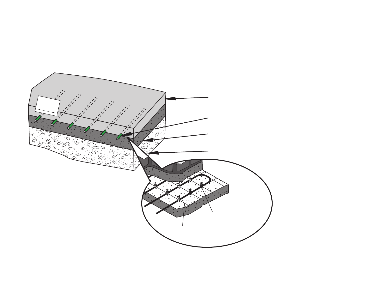
Outdoor Asphalt Snow Melt Application
Recommended Products: Snow Melt Rolls
APPENDIX B:
Plastic tie wrap
4 in (10) or 6 in (15) square 10
gauge wire mesh
CROSS-SECTION OF SNOW MELTING CABLE IN ASPHALT
3” (76mm)
Spacing
2” to 3” (51mm to 76mm) of nished asphalt
Snow Melting Mat
1.5” to 2”(38mm to 51mm) of base/primer asphalt
4” to 8” (102mm to 203mm) of crushed rock aggregate base
Note: Cables may be tied to reinforcement type mesh and then the mesh should be staked down to the base/primer pour.
11
 Loading...