

WarmlyYours TRT24030X70, TRT12015X70 Installation Manual
TempZone™ Electric Radiant
Floor Heating System (Twin Conductor)
Installation Manual
Free Design Service • 24/7 Installation Support •(800) 875-5285 • www.WarmlyYours.com

Understanding The System
How The System Works
You can feel the heat of a campre even though you are
not directly above it. Radiant energy transfer is caused
by a warm surface (the campre) giving up its heat to a
cooler surface (your body). This radiant energy travels
through space without heating the space itself. It only
turns into heat when it contacts a cooler surface. By
transferring this heat to all of the objects in the room, the
heat slowly moves to warm the air which starts to rise.
Proper Heat Dissipation
All radiant heating systems rely on a “Heat Bank”. The
heat moves from the source (Heating Element) into the
Heat Bank (thin-set) and spreads out and warms the
oor without creating an excessively hot spot. In the
WarmlyYours Floor Heating System the thin-set and/or
self-levelling cement acts as the Heat Bank. It is important
to follow the installation guidelines to create a proper
Heat Bank. For best results, we recommend a 1”- 1.5”
maximum distance between the heating cable and the top
of the tile. Wire Distances deeper than that will take longer
to heat and may not heat to expectations or satisfaction.
Insulation – Proper Heat
Retention
When WarmlyYours oor heating systems are installed on
a concrete slab, we strongly recommend adding a layer
of insulation to the slab prior to installing the radiant oor
heating system.
While WarmlyYours systems provide up to 25%
more heating power per square foot than the nearest
competitor, the slab will always act as a “heat sink.”
Some of the heat that would otherwise be transferred to
the ooring surface will remain in the slab, causing the
oor’s surface temperature to be considerably lower. This
is true with any oor heating system.
oor heating system will allow a greater percentage of the
heat generated to transfer to the ooring surface. This
leads to greater efciency and therefore faster warm up
times, higher expected surface temperatures and lower
energy usage. The oor will have the capacity to warm
to a comfortable temperature, and in some cases can be
employed as the primary heat source for that room.
Securing The Roll(s)
Once the roll(s) is tted into the space, it needs to be
secured to the suboor to prevent movement during the
installation of the oor covering. The options for securing
the roll(s) are discussed in detail on Page 5. Regardless
of the method you choose, it is vital that the integrity of
the Heating Element be maintained. Staples should never
cross, pierce or nick the Heating Element. Minimum 2 in.
spacing between adjacent heating devices.
Protecting The Heating Element
It is vital that proper care be taken to insure that the
Heating Element is not damaged during the installation
of the system or by the oor covering. A thorough
preparation and detailed inspection of the suboor
will assure that any and all objects that may damage
the Heating Element are removed prior to installation.
Heavy gauge cardboard or carpet scraps should be
used to protect the system from trafc during the ooring
installation.
Never Cut The Heating Element
The key to the system is the uninterrupted ow of
electricity through the Heating Element.
nSpiration Series Control
Thermostat Options
Option 1: nSpire Touch WiFi
This programmable model features touchscreen
operation, an easy-to-use Install Wizard, and easy access
to a detailed log of its energy use. Its WiFi capability
also means that a user can operate their heating system
remotely. It can even provide the user with weather
reports, which could make leaving your house dif cult on
some winter mornings.
Option 2: nSpire Touch
Like the nSpire Touch WiFi, this programmable model
also features touchscreen operation, an easyto- use
Install Wizard, and easy access to a detailed log of its
energy use. In addition to its modern design, the nSpire
Touch provides the user with the ability to easily program
their radiant heating system to match their needs.
Option 2: nHance
This programmable model is button-operated and
represents a blend of style and usability. By giving the
user control over the programming, this model excels
at providing optimal comfort with minimal energy
consumption.
Option 2: nTrust
This non-programmable model is button-operated and is
perfect for anyone who wants a thermostat that is both
easy to install and easy to look at. It’s sleek, minimalist
appearance blends well with almost any design theme
and operating it couldn’t be simpler.
When installed on top of a concrete slab without
insulation, it is generally accepted that a radiant oor
heating system will take the chill away from the oor and
provide a small amount of warmth.
Adding insulation on top of the slab and beneath any
1
Items Needed For The System Installation
System Components From WarmlyYours
1. The Customized Installation Plan (or layout).
2. Heating Roll(s) (15-watt/ sq. ft.) If multiple rolls are connected to the same control
device, they must be of the same voltage type and wired in parallel.
3. nSpiration Series control device
4. You may also have a relay contactor or power module, if your system is being
installed in a large area.
Ground Fault Circuit Interrupter
GFCI or ‘GFCI-breaker’ indicating its capacity if not incorporated into the control device
you are using. This is a built-in feature of the nSpiration Series controllers
Digital Ohm Meter (multi-meter)
Test the Heating Roll(s) before, during, and after the installation. A digital meter is strongly
recommended because of the precise measurements needed.
IMPORTANT - Cross check the items you received against the packing
list and the materials list on the installation plan to ensure that the roll
length(s) and thermostat type(s) are an exact match.
Double Check Your Dimensions
Check and verify that your plan has the correct room dimensions. Your order consists of
the exact amount of material required to complete your project. If the measurements of
your space have changed, this will affect how much product is required and how it will be
installed. Once the Heating Roll is cut into panels, it cannot be returned. If you have any
discrepancies or questions, call WarmlyYours at (800) 875-5285.
Circuit Check (Not a substitute for an OHM meter)
This device, available from WarmlyYours, is a continuity checker that you connect to the
cold lead wires before installation of the ooring material.
Electrical Housing Boxes/Switch Plates
All control devices except a Relay Contactor t into a double gang box. If a double gang
box is used it will need to be tted with a single gang mud ring. We strongly recommend
a double gang box with a single gang mud ring as it provides more room to place all the
wires. Heating elements of cables shall be separated at least 200mm (8 in.) from the edge
of outlet boxes and junction boxes that are to be used for mounting surface luminaires. A
clearance of not less than 50 mm (2 in.) shall be provided from recessed luminaires and
their trims, ventilating openings, and other such openings in room surfaces. No heating
cable shall be covered by any surface-mounted equipment.
Electrical Conduit
Local electrical codes often require the power leads be inside a metal or plastic conduit
when running through the wall from the Heating Roll to the control device. When using an
in-oor sensor, if local code requires the low voltage sensor wire be housed in conduit, it
must use a separate conduit from the power leads(high voltage).
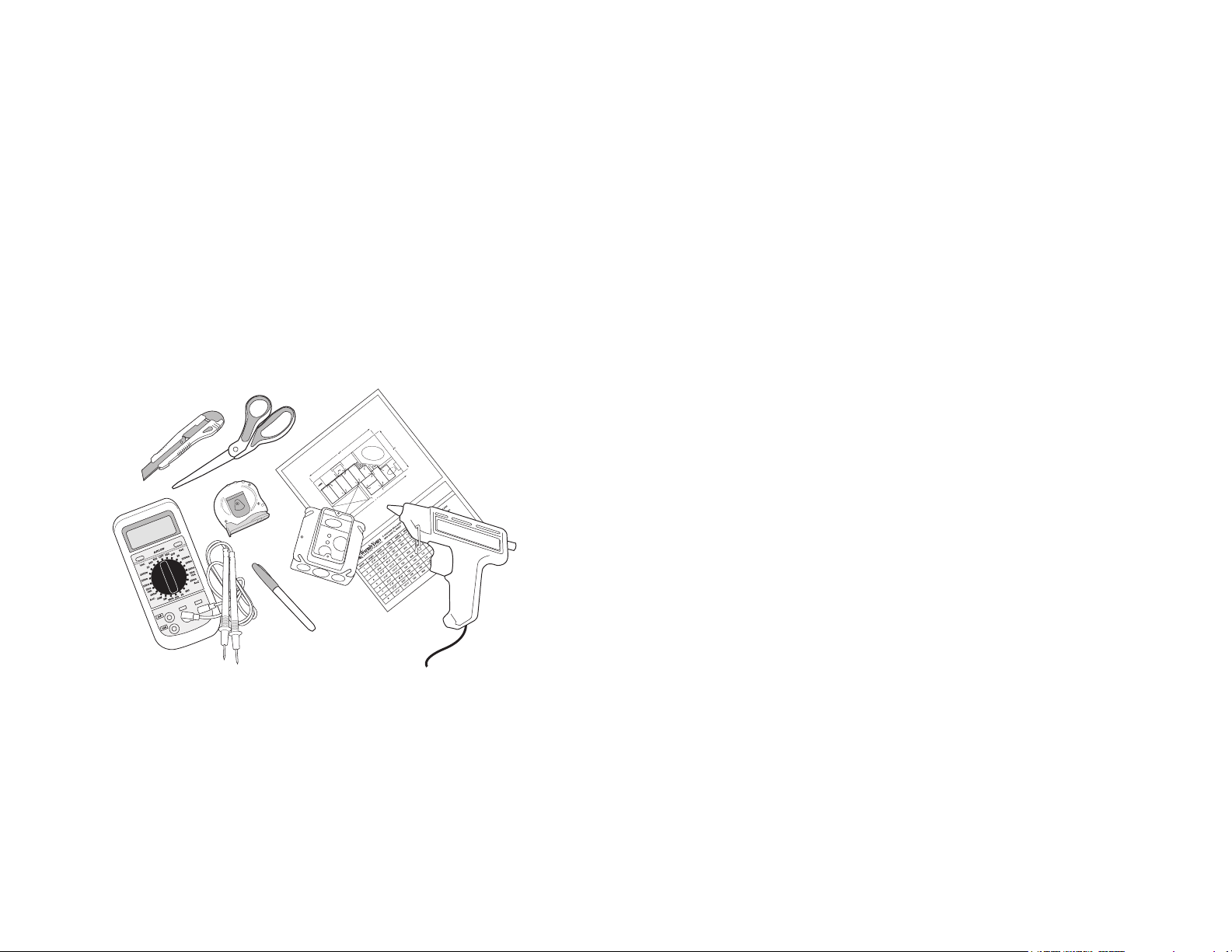
A Permanent Marker And Tape Measure
To measure and mark Installation Plan points onto the prepared suboor as well as where
to alter the Fiberglass Mesh of the Heating Roll(s).
Utility Scissors
Scissors are the best tool to trim and alter the Fiberglass Mesh of the Heating Roll and to
separate any lengths of Heating Element from the Mesh. Never cut the Heating Element.
Hot Glue Gun, Double-Sided Tape and/or Stapler
Use these tools to afx the Fiberglass Mesh portion of the Heating Roll to the prepared
suboor before covering with thin-set cement. Beware that misuse of a stapler can cause
damage to the Heating Element. NEVER staple across or on top of the wires. Hi-temp
duct tape, like 3M 6969 is suggested.
Off-Cuts Of Cardboard Or Carpet Scraps
This protects the Heating Element during the installation.
2
Understanding The Customized Installation Plan
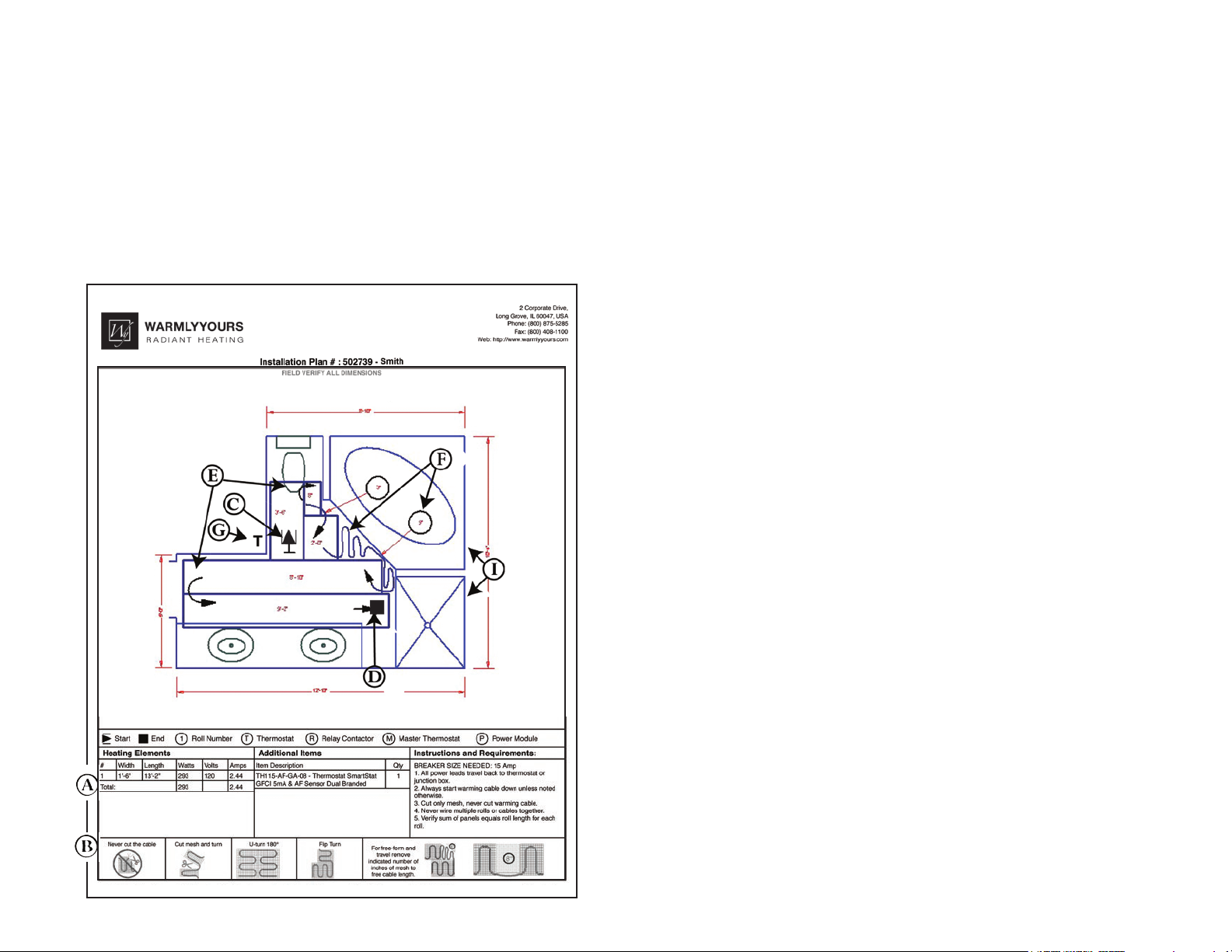
The Customized Installation Plan
This is your key to a successful installation. Your plan has been custom designed
for your individual project based on the dimensions you gave us. It will indicate the
placement of each Heating Roll, the electrical service requirements, and the location
of the control device(s). It should be reviewed to verify that the dimensions of your
room are accurate as well as the location of the permanent xtures in your space. If
you have made any alterations to your oor plan, contact WarmlyYours to have
your Installation Plan updated.
A. Materials List:
Indicates the items included in your order.
B. Legend:
Description of the items on the Installation Plan.
C. Starting Point:
Indicates where the Heating Roll(s) starts.
D. Ending Point:
Indicates the end of the Heating Roll(s).
E. Turn:
Indicates where the “Mesh” needs to be cut to make a turn allowing the roll to continue
in a new direction. See Page 5 for full details on how to execute turns.
F. Free Form Space:
Indicates a length of Fiberglass Mesh that needs to be removed and separated from the
Heating Element. For every 3” of Mesh removed, 1’ 6” of Heating Element will be freed
on 18” wide rolls, and on 36” wide rolls, 3’ of heating element will be freed. This “free” wire
should be manually positioned on the oor and secured with tape or glue. Staples are
never recommended on the Heating Element.
G. Control Device:
Indicates where the control device is to be located on the wall.
H. Notes:
Indicates any additional information you may need including the total watts and amps
drawn by the Floor Heating System.
I. Permanent Fixtures:
Indicates the location of permanent xtures. Please note that these xtures must not be
placed on top of the heated area.
IMPORTANT - Cross check the items you received against the packing
list and the materials list on the installation plan to ensure that the roll
length(s) and thermostat type(s) are an exact match.
3
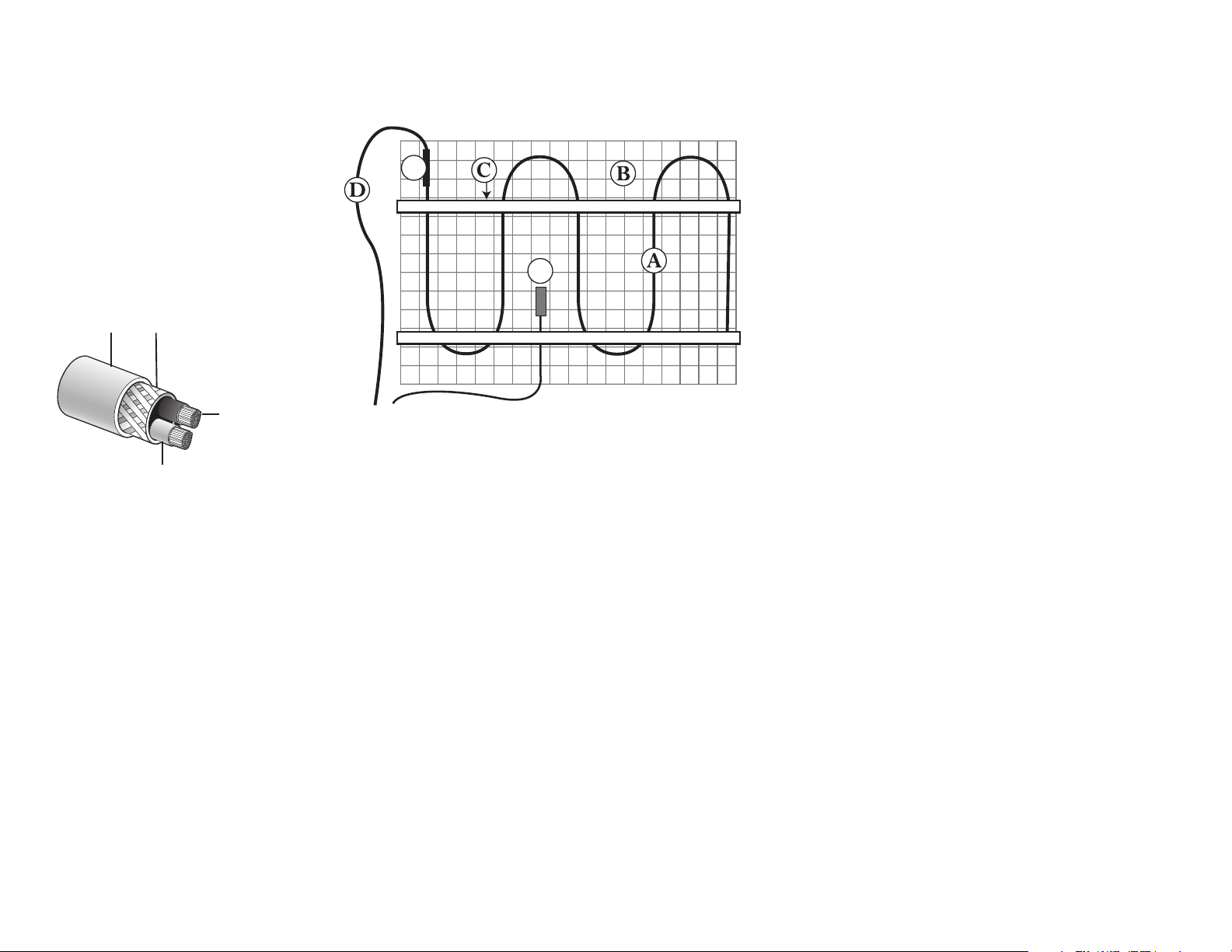
The Heating Roll
A. Heating Element
B. Fiberglass Mesh
C. Tape
D. Cold Lead Wire
E. Factory Splice
F. Floor Sensor (optional)
Secondary
Flouropolymer
Insulation
Metal Braiding
Connected to Ground
Solid
Conductor
Wire
Primary
Flouropolymer
Insulation
Warmlyyours Floor Heating System.
Relay Contactor or Power
E
F
Modules (not required for all
systems)
Systems installed in large spaces will most likely require a
Relay Contactor or Power Module(s) in addition to the control
device to operate properly. The Relay or the Power Modules
may be located in the same vicinity as the control device. If your
system will be using this option, all cold leads will be connected
to the relay contactor or power module and not directly to the
control device.
Heating Roll(s): Types and Sizes
Roll(s) are rated at 15-watts per square foot and vary in length.
Each roll is designed to draw a specic amount of electricity
and therefore produce the proper amount of heat based on its
length. For this reason, the length of the roll(s) can never be
shortened to make a proper t. Your Installation Plan has been
designed to specically accommodate your space. The same is
true for rooms that have multiple rolls. Multiple rolls are never
wired to each other. Each roll is wired in parallel to the control
device or relay contactor.
The Heating Element
The Heating Element consists of two copper alloy resistance wires covered by Flouropolymer insulation. A braided metal
surrounds the primary Flouropolymer insulation and serves as ground sheath. The Heating Element (A) attached with
tape (C) in a serpentine pattern to a exible Fiberglass Mesh (B). The Fiberglass Mesh is designed to keep the Heating
Element evenly spaced throughout the roll. The cold lead return wire is factory installed at one end of the Heating Roll and
must run back to the power supply along the perimeter of the heated space. The power lead (D) is 15-feet in length. The
lead is spliced to the Heating Element (E) at the factory. If necessary, this lead wire may be shortened or even extended.
Please note the thickness of the factory splice and cold lead and plan accordingly. The factory splices must be completely
embedded in thinset or self-leveling underlayment.
Floor Sensor (not required for all systems)
Temperature sensor wire must be tested before and after installation and must measure between 8k to 12k ohm for
temperatures between 68-86 F (20-30C). This measurement must be done with a digital ohm meter, set to the 20k range.
Beware of self-ranging meters and analog meters.
Systems using a nSpiration Series control require a Floor Sensor (F). This Sensor is embedded in the oor and monitors
the oor temperature. The Floor Sensor should be centered in between 2 resistance wires leaving approximately 1.5” on
either side and extend about 6” into the heated area. Avoid placing the sensor in an area affected by a draft, a radiator
or the sun. Must be installed if using a thermostat. Some people choose to install a second (Backup) sensor. For an
additional cost you may purchase a second sensor. NEVER run the sensor wire over, under, or next to a heating wire.
Sensor wires can touch the non-heating cold lead, but must not run next to the lead for more than a couple of inches and
never run in the same conduit as the cold leads.
Working with the Heating Roll(s)
The roll(s) that make up your system have been selected to
t into your oor plan. The Installation Plan shows precisely
where each roll starts and ends. The “Lead Wire” on each roll
is designed to travel back to the control device location. These
wires do not heat. All connections are made at this point. While
it may be required to cut and alter the “Fiberglass Mesh”, the
“Heating Element” must stay intact. Page 5 shows in detail
how to make the necessary turns to install your Floor Heating
System.
Separating the Heating Element
from the Mesh
During the installation, you may need to separate the Heating
Element from the Fiberglass Mesh. This can be done provided
the Heating Element is not cut and the shielding is not nicked
or punctured. It will be necessary to do this when releasing the
Heating Element to make step turns and position it in a “Free
Form” space.
4

One Good Turn Deserves Another
The complimentary Installation Plan provided by the
WarmlyYours team is very important. It shows the
recommended placement of your Heating Roll(s) for
safety and optimal efciency. The plan will also serve
as the reference for any future inspections or oor work
that needs to be performed.
The Heating Element of the WarmlyYours product is
sewn in a serpentine pattern onto lengths of Fiberglass
Mesh forming a roll. It is quick and simple to cover large
areas.
Your plan shows you where any modication is
necessary. These are all easily done by cutting through
the Fiberglass Mesh material (NOT the Heating
Element), see Photo A , so that the roll is in two or more,
moveable -but connected- pieces which are called
“Panels”, see Photo B. These panels can be angled,
turned or completely ipped over in order to cover the
space.
To cover very small or odd shaped areas, the Heating
Element is used in “Free Form”. A section of the
Fiberglass Mesh is removed in order to release an
appropriate length of Heating Element to ll the space.
This “free” wire is placed in areas not reached by the
main Heating Elements of the panels. It is also used to
make “step turns” possible. Always maintain 3” spacing
in all free form and step turns.
To release the required amount of Heating Element for
a free form area, rst make the two straight cuts and
then carefully remove it.
Cut & Turn
By cutting only the Mesh (see Photo A), you can move
the remaining section of the Heating Roll in a new
direction. By doing this, you are creating what are now
referred to as “panels.” (see Photo B). This is the rst
step in any turn or alteration of the Heating Roll(s). A
turn is indicated on the Installation Plan by an arc with
an arrowhead. By examining the relationship between
two panels, you will determine the type of turn needed.
Free Form
Free form spaces are lled with loose lengths of Heating
Element. A wavy line with an arrow will appear on the
Installation Plan to indicate the area that needs to be
lled. This symbol is accompanied by a unit of measure
in a circle that will indicate the amount of Fiberglass
Mesh to be removed. (See Page 6, on Installation
Plan.) Once the tape is trimmed, the Heating Element
separated and the Fiberglass Mesh removed, position
the Heating Element by hand and secure it to the oor
with Hot Glue or Tape. Try to maintain the 3 inch spacing
similar to the spacing on the Heating Roll(s).
Installation Recommendations
The space heating cable shall not extend beyond the
room or area in which it originates.
The space heating cable is not installed in closets,
over walls or partitions that extend to the ceiling, or
over cabinets whose clearance from the ceiling is less
than the minimum horizontal dimension of the nearest
cabinet edge that is open to the room or area.
Isolated single runs of cable may pass over partitions
where they are embedded.
The cable is not to be installed in walls.
The minimum distance between adjacent runs shall be 2 in.
Inspect and remove damaged or defective cables
before they are covered or concealed.
Mark the appropriate circuit breaker reference label
indicating which branch circuit supplies the circuits to
those electric space heating cables.
Minimum installation temperature for the wire is 5ºF
(-15ºC). See Adhesive instructions for recommended
minimum installation temperature.
For best results, we recommend a 1”- 1.5” maximum
distance between the heating cable and the top of the
tile.
Photo A
Photo B
5
 Loading...