

Installation Manual for Snow Melting
24/7 Installation Support • Lifetime Technical Assistance • Free Design Service • www.WarmlyYours.com • (800) 875-5285

CONTENTS
1.0 Product Specications ............................................................................. 1
2.0 Selection of the Heating System ................................................................ 2
1.0 PRODUCT SPECIFICATIONS
WarmlyYours Heating Cable is designed for concrete slab oors of new homes,
outdoor driveways, walkways, stairs and patios. It is well suited for large areas like
basements, garages, additions and driveways.
3.0 Important Instructions before Installing the System................................... 2
4.0 Installation for Slab Heating ....................................................................... 3
4.1 Temperature Controller & Sensor ....................................................... 3
4.2 Electrical Provisions for the System ................................................... 3
4.3 Pre-Installation Preparations .............................................................. 4
4.4 Installation for Concrete Embedded Applications .............................. 4
4.5 Operating Tips .................................................................................... 5
5.0 Installation for Snow Melting ...................................................................... 5
5.1 Control for Snow Melting System ...................................................... 5
5.2 Electrical Provisions for the System ................................................... 5
5.3 Installation under Asphalt ................................................................... 6
5.4 Installation under Concrete ................................................................ 7
5.5 Installation in mortar under Pavers .................................................... 8
5.6 Installation of Snow Melting Mat ........................................................ 9
6.0. Testing the Mats and Cable ....................................................................... 10
6.1 Control for Snow Melting System ...................................................... 10
6.2 Electrical Provisions for the System ................................................... 10
7.0 Warranty ..................................................................................................... 10
The Heating Cable is comprised of a dual, multistrand heating element with a primary
insulation of Fluoropolymer. The insulated core is then protected with a woven metal
braid and an outer jacket of PVC, EPR or Zero Halogen Polyolen based compound
to make it sturdier and to provide corrosion protection. These cables are terminated
with 20’ (6.1m) long standard cold leads. The hot and cold junction is uniquely
designed to make it 100% fool proof.
The Snow Melting Mat is a cable in mat construction (for snow melt applications)
which consists of the Heating Cable taped on a Polypropylene (PP) mat. The Heating
Cable is laid in a serpentine fashion so that it is equally spaced and distributed on
the (PP) mat.
Available in a wide range of capacities and sizes to suit your requirements, the Snow
Melting Mats and Heating Cables are identied as indicated below.
Item Number: AAAA-BBB-CCCC
Ex: Item Number: WHMA-240-0250
• AAAA = WHMA for Snow Melting Mat, WHCA for Snow Melting Cable and
• BBB = Operating Voltage available in 120V and 240V
(product type) (voltage) (width & length = 2’x50’)
WSHM for Slab Heating Mat, WSHC for Slab Heating Cable
8.0 Appendix
Appendix A: WarmlyYours Snow Melting Mats ................................................. 11
Appendix B: WarmlyYours Snow Melting and Slab Heating Cables ................. 12
Appendix C: Cross-Section of Snow Melting Cable in Asphalt ........................ 13
Appendix D: Cross-Section of Snow Melting Cable in Concrete ...................... 14
Appendix E: Cross-Section of Snow Melting Cable in Mortar Under Pavers ... 15
Appendix F: Cross-Section of Indoor Slab Heating Cable in Concrete ............ 16
Appendix G: WarmlyYours Snow Melting System Diagram Premium ............... 17
Appendix H: WarmlyYours Snow Melting System Diagram Economy .............. 18
Appendix I: WarmlyYours Snow Melting System Diagram Manual ................... 19
Appendix J: WarmlyYours Snow Melting System Diagram Value ..................... 20
Appendix K: WarmlyYours Interior Slab Heating System Diagram ................... 21
9.0 Warranty Registration ................................................................................. 22
• CCCC = Mat width in ft. (rst two digits) and Mat length in ft. (third and fourth
digits) for Snow Melting Mat and Slab Heating Mat, Cable length in ft. for
Snow Melting Cable and Slab Heat Cable
The available sizes of Snow Melting Mats are shown in Appendix A. The available
lengths of Snow Melting and Slab Heating Cables are shown in Appendix B. Both
Appendices include the following attributes for each Item Number.
• Product Type • Watts/Ft for Cable or Watts/Sq Ft for Mats
• Operating Voltage • Amps
• Cable Length
• Mat Width and Length
• Total Ohms
• Total Watts
1
2.0 SELECTION OF THE HEATING SYSTEM
Selection of your Heating System will depend on the application. The following can
be taken as a general guide:
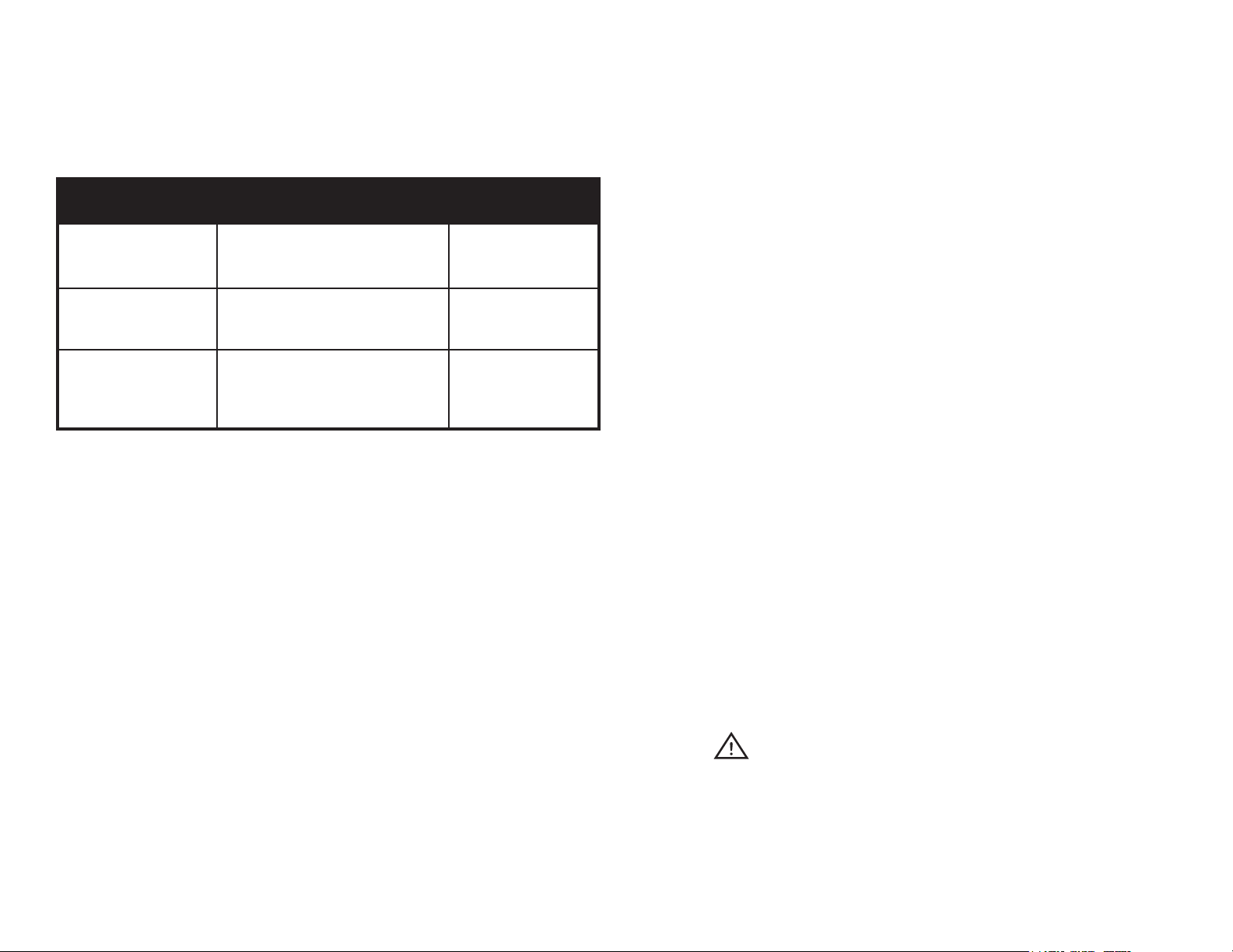
INSTALL CHART
Application
Outdoor Snow Melting
Outdoor Slab Heating
Watts per Sq.Ft. (per Sq.M.)
- Cable spacing inches (mm)
45 to 55 W/ft2 (4.18 to 5.11 W/m2)
Recommended spacing 3” (76mm).
25 to 35 W/ft2 (2.32 to 3.25 W/m2)
Recommended spacing 4” to 6” (102
to 152 mm).
Multiplier at
given spacing
4.0 at 3” (76mm)
3.0 at 4” (102mm)
2.4 at 5” (127mm)
2.0 at 6” (152mm)
4. Take precautions to avoid damage to Heating Cable during installation. Do not
drive over cable. Duct tape the ends of shovels. Do NOT saw expansion joints,
without having lines marked o clearly with spray paint, where installer has
veried that Heating Cables will not be cut. Do NOT damage Cables with heavy
equipment, machinery or vehicles.
5. Heating Cables should be separated from other heat sources such as luminaries
and chimneys.
6. Do not install the Heating Cable below 5˚ F (-15˚ C) ambient temperature.
7. Minimum bending radius of the Heating Cable shall not be less than 10 times its
diameter.
8. Minimum spacing of Cables is 3” (76 mm) and maximum spacing of Cables is
12” (305 mm).
1.7 at 7” (178mm)
1.5 at 8” (203mm)
1.3 at 9” (229mm)
1.2 at 10” (254mm)
Indoor Slab Heating
15 to 20 W/ft2 (1.39 to 1.86 W/m2)
Recommended spacing 7” to 10” (178
to 254mm).
Note: The heated cable spacing is mandated to generate a maximum of
15Watts/ft2 (161Watts/m2) of output in applications where a oor covering, such as
carpet, tile, or wood, is placed over the slab.
Formula: Area of Application x Multiplier at given cable spacing = Heated Cable
Length required
Example 1 (English): 100 sq.ft of Outdoor Snow Melting x 4.0 at 3” spacing = 400
feet of Heated Cable required
Example 2 (Metric): 9.3 sq.m of Outdoor Snow Melting x 4.0 at 76mm spacing =
37.2m of Heated Cable required
Please note the above-indicated values are meant as a general guide. Your values
mat vary depending on a number of factors. Please consult your Account Manager
for assistance.
3.0 IMPORTANT INSTRUCTIONS BEFORE INSTALLING THE SYSTEM
1. Heating Cable must not cross or overlap itself at any point. This could cause the
Cable to overheat, requiring replacement.
2. The Heating Cable length should not be cut or altered under any circumstances.
This may cause over heating resulting in damage to the Cable.
3. The cold lead can be cut /extended with a conventional splice, inside of an
accessible junction box (weatherproof if outdoors).
9. Twin Conductor Heating Cable has a ground braid (metal sheath) to be connected
to ground and 2 conductors which are to be connected to the power supply.
10. Double check the voltage and wattage of the Heating Cable received against the
project specications on your custom installation plan. These are marked on the
packing box of the product. A qualied electrician should connect the Heating
System.
11. Check the continuity, resistance and insulation resistance of the Heating Cable
before installing and also after installing. Resistance value should match the
value shown in Appendix A on page 12. A tolerance of -5% to +10% is allowed.
Insulation resistance must be more than 10 megohms.
12. Keep high voltage power wires in a separate conduit from the low voltage wire.
13. Allow sucient drying or curing period of the oor / slab / concrete / asphalt after
installing the Heating System and before energizing the Heating System.
14. For easy reference, x a label at the power distribution board indicating the
location of the heating units installed.
WARNING
15. The Cable must NOT be shortened or cut in any manner or subjected to strain
at the splice joint.
16. NEVER power up Heating Cables prior to being buried in concrete, asphalt or
in mortar (even for testing purposes). This will prevent premature failure of the
Heating Cable.
2
4.0 INSTALLATION FOR INDOOR & OUTDOOR SLAB HEATING
2’ (61cm)
or
3’ (91cm)
20’ (610cm) Cold Lead
Metal Sheath (Copper/Galvanised Steel/Cladded Steel)
Primary Insulation (Fluoropolymer)
Heating Conductor (Solid/Multistrand)
10"
(251mm)
3"
(8cm)
110V / 230V AC SUPPLY
4.1 TEMPERATURE CONTROLLER & SENSOR
We recommend a standard Programmable Thermostat with a temperature sensor
specially designed for control of the Heating System.
WARNING
Heating Cable should be connected to a Ground Fault Circuit Interrupter (GFCI)
equivalent having a rated residual operating current not exceeding 30mA. Consult a
qualied electrician.
The sensor normally comes with a lead wire of 15 feet (4.5m) in length. Thermostat
sensor location shall be centered between two adjacent runs of Heating Cable within
metal pipe or conduit to allow for replacement. Do not position Thermostat sensor
closer than 1.5 inch (38 mm) to Heating Cable. Sensor cable shall be routed to the
Thermostat located in the wall at suitable operating height. Always install Thermostat
indoors, even when used in conjunction with exterior slab heating.
Do not allow any other Heating Cable to overlap with the sensor cable.
The details of the thermostats and installation guidelines are given in the instruction
manual provided with the Thermostat.
4.2 ELECTRICAL PROVISIONS FOR THE SYSTEMS
The Heating System installation wiring shall be in accordance with the National Electric
Code and any applicable local codes. Controls and accessories recommended for
use along with the Heating Cables are listed below:
• Floor Sensing Temperature controller / Thermostat
• GFCI (Ground Fault Circuit Interrupter)
• Dedicate Circuit Breaker(s) for all heater circuits
• Plastic or wire zip ties
In case the GFCI trips during normal operation, and cannot be reset, there is likely a
fault in the Cable. No attempt should be made to re-energize the system. The GFCI
must not be bypassed under any circumstances. Consult a qualied electrician.
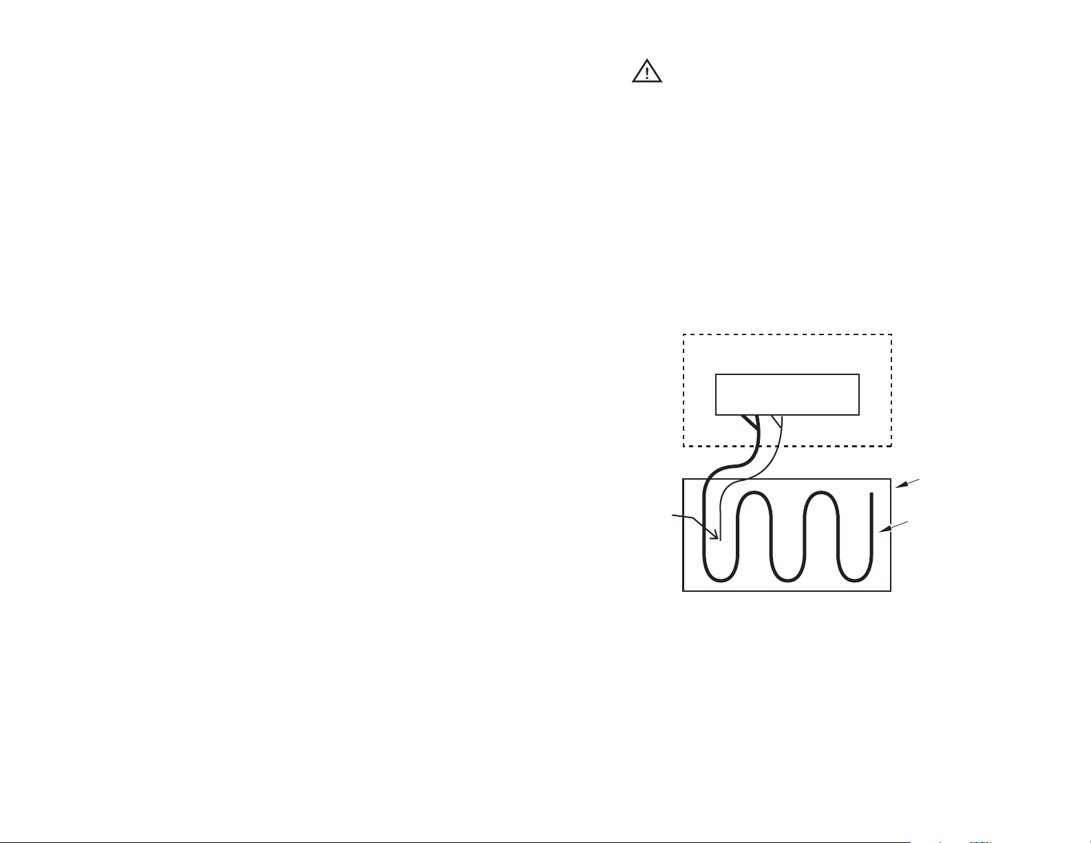
THERMOSTAT
FLOOR
SENSOR
HEATING
CABLE
The location of the Thermostat junction box shall be about 4’ (1.2m) high from the
oor for easy access. The oor sensor wire and the Heating Cable cold leads shall be
routed to the Thermostat / power connection box in separate conduits.
If the Heating System has a load below 1,750W at 120V or 3,500W at 240V based
on thermostat power rating, it may be connected directly to an electronic thermostat
as shown in Diagram A which gives a typical scheme of the electrical system. If the
Heating System has a load more than the thermostat power rating, consult your
WarmlyYours Account Manager.
HEATING SYSTEM
DIAGRAM A
3

4.3 PRE-INSTALLATION PREPARATIONS
1. Review the custom installation plan for the area requiring the Heating System
and verify dimensions listed against your actual eld dimensions to ensure they
match.
2. Conrm the location of the power supply box/Thermostat and sensor against the
plan.
3. Select Heating Cable(s) and ensure that the procured Cable is correct according
to the requirements in the following section.
4. Check the Slab Heating Cable in the box visually and make sure that it is not
damaged. Check voltage, wattage, resistance values from the factory test record
and verify that they match the required specications.
5. Check resistance of Heating Cable and its insulation resistance with a multimeter/
megohmmeter as soon as it is removed from its packing. Resistance value of
the Heating Cable shall match to the value shown in Appendix A on page 12. A
tolerance of -5% to +10% is allowed. Insulation resistance shall be more than 10
Megohms. Record it on the warranty card located on page 22 of this manual.
6. The Heating Cable is now ready for installation.
7. Heating Cable should be laid so that the Cables are equally spaced. The distance
between two Heating Cable passes should be according to the spacing calculation
determined by WarmlyYours. No heating cable shall be covered by any surfacemounted equipment.
8. Route the power leads through a conduit from the oor to the connection box. If
multiple cables are being used, route all power leads through a conduit from the
oor to the connection box in the wall.
9. Check the resistance and insulation resistance value after laying out Cables.
Check to see if these values are consistent with the pre-install values. Record
values in the warranty card on page 22.
10. At this point, the concrete can be poured.
11. Pour the concrete and spread evenly on the reinforcement mesh / grid. The
concrete oor or slab thickness shall be about 2” (51 mm) on top of the Heating
Cable.
12. Ensure the entire Heating Cable, factory splices and thermostat sensor (in
metal conduit) are embedded in the cement mortar. The choice and application
of building materials should be in accordance with the building material
manufacturer’s instructions.
4.4 INSTALLATION FOR INDOOR CONCRETE SLAB APPLICATION
1. Reinforcement mesh on the oor or slab should be strong enough when walked
on for installation of the Heating Cable.
2. Reinforcement mesh should be properly positioned and supported so that it does
not get disturbed during the concrete pour. Ensure the Heating Cable is on the
reinforcement mesh a minimum of 2” (51mm) below the nished concrete/slab
surface.
3. Surface preparation of the oor is very important. The oor must be completely
free of all debris including all nails, sharp metallic objects, wood and construction
debris. Make absolutely sure that there are no objects on the oor that might
damage the Heating Cable.
4. Start installing Heating Cable from the location of power connection box.
5. Roll out the Heating Cable. Secure it to the reinforcement mesh or grid using
plastic zip ties (supplied by installer).
6. Heating Cable should be laid 3” (76mm) away from the wall perimeter.
13. Ensure the correct curing time for drying of construction materials is followed
before powering ON the Heating Cables.
14. Check the continuity, resistance and insulation resistance values after the
concrete or mortar is poured. They should be consistent with the values recorded
previously. Record values on the warranty card on page 22 of this manual.
WARNING
The heated cable spacing is mandated to generate a maximum of
15Watts/ft2 (161Watts/m2) of output in applications where a oor covering, such as
carpet, tile, or wood, is placed over the slab.
4
4.5 OPERATING TIPS
Heating Conductor (Solid/Multistrand)
20’ (610cm)
Cold Lead
SENSOR
HEATING
CABLE
FLOOR
HEATING SYSTEM
THERMOSTAT
110V / 230V AC SUPPLY
1. Energy consumption will vary depending on ambient temperature and building
insulation. For lower energy consumption, use a 7-day Programmable Thermostat
control.
120 VAC SUPPLY
SNOW
SENSOR
2. Energy consumption can be minimized by turning the system OFF when heating
is not required, but extra time will be required for the oor to warm up once the
system is turned ON again.
3. Avoid placing objects like thick Mats, rugs, oor level furniture and mattresses
on the heated oor, especially in the area where the oor temperture sensor is
located. These restrict the transfer of heat away from the Cables and result in the
oor area beneath them being warmer than other areas.
4. Avoid Mats with rubber or vinyl type backing as these may decompose with heat
and could stain ooring.
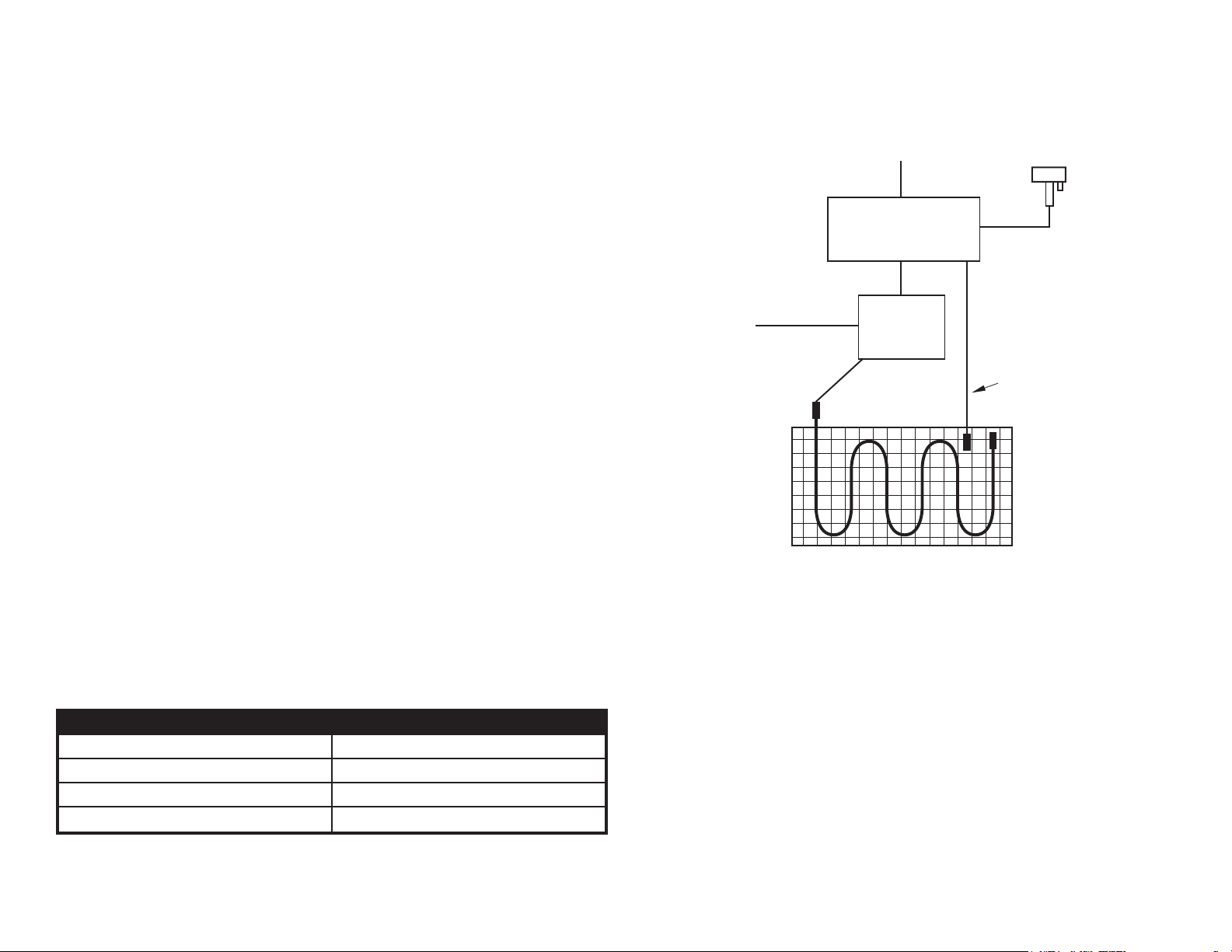
5.0 INSTALLATION FOR SNOW MELTING
5.1 CONTROL OF SNOW MELTING SYSTEM
A control suitable for Snow Melting systems with pavement mounted or aerial
mounted sensor should be used for Snow Melting applications.
5.2 ELECTRICAL PROVISIONS FOR THE SYSTEMS
The Snow Melting system installation wiring shall be in accordance with the National
Electric Code and prevailing local codes.
CONTROL
120 VAC
or
240 VAC
SNOW MELT MAT
DIAGRAM B
PANEL
RELAY
PANEL
SLAB TEMP HIGH
LIMIT SENSOR
The snow / moisture sensor cable and the Heating Cable cold leads shall be routed
to the power connection box in separate conduits.
Breaker Size (Amps) Max Design Load (Amps)
40 32
30 24
20 16
15 12
5

5.3 INSTALLATION UNDER ASPHALT
1. Ensure that paving contractor has a solid base of 4” to 8” (102 mm to 203 mm) of
crushed rock aggregate tamped down and ready to receive the asphalt.
2. It is extremely important that the paving installer does NOT use any heavy
equipment, machinery, or vehicles over the exposed Heating Cable. Any tracked
mechanical spreaders or dump trucks must be prohibited from running over
exposed Heating Cable.
3. During this process of laying asphalt, installing the heating product, and
laying more asphalt, it is the responsibility of the electrician to use a 500 VDC
megohmmeter and a multi-meter to continuously check the Heating Cables that
are being worked on top of, to ensure they have not been damaged.
4a. The paving installer should lay down the binder / base coat of asphalt and roller it
smooth. The paving installer must decide if this binder coat of asphalt is allowed
to cool before nishing with the top coat of asphalt. This should be coordinated
with the installer of the Heating Cable or Mats. When working on top of hot
asphalt, please consider pre-making “wire mesh heating Mats”. This means
rolling out the reinforcing wire mesh (provided by electrician) and pre-attaching
the Heating Cable to it using wire ties (like rebar wire ties) that will not melt from
the hot asphalt. These “wire mesh heating Mats” could be left in the yard next
to the driveway while the rst binder coat is poured. While the asphalt is still hot,
two people could carry / drag each “wire mesh heating mat” over the hot asphalt,
have it ipped over so that it is wire-side-down / mesh-side-up, and then staked
down to the hot binder coat (stakes provided by electrician).
4b. If the paving installer decides to let the binder / base coat of asphalt cool prior
to nishing with the top coat, then wire mesh is only needed for free-form type
Heating Cable installations. WarmlyYours Snow Melting Mats may be staked
down to the binder coat without using any wire mesh (stakes may only pierce the
black plastic mesh, and should never make direct contact with the Heating Cable
itself). Again, it’s recommended that the Snow Melting Mat be laid down so it
is wire-side-down / mesh-side-up, to help protect it from damage by shovels.
When installing free-form type Heating Cable, stake wire mesh down to the
binder / base coat rst, and then attach the Heating Cable to it using wire ties.
This means it is wire-side-up / mesh-side-down, so extra care must be taken by
the paving installer to avoid damaging the Heating Cables with shovels or rakes
used to spread the top coat of asphalt.
5. Once the heater cables are in place, the electrician must route the cold lead(s),
(20 ft (6.1m) provided per each Mat / Cable) through rigid metal conduit(s) to get
back to an accessible weatherproof junction box(s). The electrician may supply
junction boxes which can be accessed from above, so the rest of the box is
buried to avoid damage by lawn mowers and/or vehicles. Care must be taken by
the electrician so that none of the heated section of Cable enters the conduit(s).
If a slab-mounted snow sensor will be used, this is the best time for placement.
It should be located in an open area, away from trees or bushes, so that snow
will easily fall directly on it. Separate conduit should be used to protect the low
voltage sensor wire and must NOT be shared with any high voltage cold lead
from the Heating Cables / Mats.
6 . Once the Heating Cables and conduits are in place, and are attached by the
above methods listed, the nal top coat of asphalt may be poured. At least
2” (51mm) of material must cover the Heating Cable. The paving installer will
be required to spread this around evenly with shovels and rakes. Shovels
should be duct taped so the blade ends are less sharp. Again, the topping coat
should be spread manually to avoid use of heavy machinery. The only time it is
acceptable to use a mechanical asphalt spreader would be when it can straddle
tire track coverage used for longer sloped driveways. Tire track coverage allows
the spreader machine to be used without it ever making any direct contact with
the Heating Cables.
7. Once the top coat of asphalt is spread over the Heating Cables evenly with at
least 2” (51 mm) thick coverage, it may be rolled over with the steam roller to
nish / atten the driveway. Again, each Heating Cable / Mat must be tested
with a multi-meter and 500 VDC megohmmeter to verify that they have not been
damaged, and to ensure they will be ready for activation (nal test) after the
asphalt has cured. These values should be recorded on the warranty card on
page 22.
6

5.4 INSTALLATION UNDER CONCRETE
1. Ensure that the concrete contractor has installed a solid base of 4” to 8” (102 mm
to 203mm) of crushed rock aggregate base and that it is tamped down and ready
for the concrete pour.
2 . It is extremely important that the concrete installer does NOT use any heavy
equipment, machinery, or vehicles over the exposed Heating Cable. During
concrete pours, it is recommended that care be taken to avoid stepping on the
transition portion of cable, where the hot section (green) meets the cold section
(black). This is the location of the factory splice. During this process of installing
the heating product and pouring concrete, it is the responsibility of the electrician
to use a 500 VDC megohmmeter and a multi-meter to keep checking on the
Heating Cables that are currently being worked on top of, to ensure they have not
been damaged, and will be ready for action once the concrete slab has cured.
3. For installations in stairs and ramps that will include hand rails, it is strongly
recommended that the concrete installer pre-sleeve for the posts to avoid any
and all drilling of the concrete. The Heating Cable must be routed around these
sleeves or posts to avoid any direct contact with them. Heating Cables or Mats
must not be allowed to pass thru expansion joint locations. It is recommended
that lines are spray painted on the nished concrete surface by the electrician to
mark o exactly where expansion joints may be located. It is the responsibility of
the electrician and the concrete installer to coordinate their eorts so they avoid
saw-cutting or drilling thru Heating Cables that are no longer visible beneath the
concrete. Following the proposed installation plan from WarmlyYours will help to
ensure this process goes smoothly.
4a. For Two-Pour Installations: The concrete installer pours the rst 2” to 3” (51mm
to 76mm) of concrete. While this rst pour is still wet, rebar or wire-mesh should
be placed on top of the rst pour. The Snow Melting Mats / Cables should be
attached to the rebar / mesh with plastic zip ties, using 3” to 4” (76mm to 102mm)
spacing for free-form type cable. At this time, the electrician must route the cold
lead(s) thru rigid metal conduit(s) to get back to an accessible weatherproof
junction box(es). Care must be taken by the electrician so that none of the
heated section enters any conduit. If a slab-mounted snow sensor will be used,
this is the best time for placement. It should be located in an open area away
from trees or bushes so that snow will easily fall directly on it. Separate conduit
should be used to protect the low voltage sensor wire and must NOT be shared
with any high voltage cold lead from the Heating Cables / Mats. Once conduits
& sensor(s) are placed, the topping pour of concrete can be nished. Again, the
concrete installer(s) must take care not to walk on the hot-cold splice point, and
to avoid damaging the Heating Cables with shovels and rakes. Taping up the
shovel blades helps make them less sharp. Like with asphalt, it’s recommended
that Mats be placed so the mesh faces up, keeping the wire-side-down to help
protect it from the shovels.
4b. For Single-Pour Installations: The wire mesh or rebar is rst placed by the
concrete installer or electrician. The electrician then must attach the Heating
Cable to the rebar / mesh with plastic zip ties using 3” to 4” (51mm to 76mm)
spacing for free-form type cable. Then the rebar / mesh must be propped
up with concrete rubble, wire chairs, or brick pavers to the appropriate depth
so that Heating Cable / Mat ends up 2” to 3” (51mm to 76mm) from nished
surface and no deeper. Once rebar / mesh / Heating Cable is all propped up, the
electrician must route the cold leads(s) thru rigid metal conduit(s) to get back to
an accessible weatherproof junction box (es). Care must be taken so that none
of heated section enters any conduit. If a slab-mounted snow sensor will be
used, this is the best time for placement. It should be located in an open area,
away from trees or bushes, so that snow will easily fall directly on it. Separate
conduit should be used to protect the low voltage sensor wire and must NOT be
shared with any high voltage cold lead from the Heating Cables / Mats. Once
conduits & sensor(s) are placed, the pour of the concrete can be nished in one
step. The concrete installer(s) must take care not to walk on the hot-cold splice
and to avoid damaging the Heating Cables with shovels and rakes. Mats should
be placed mesh facing up, keeping the wire-side-down, to help protect it from
the shovels and rakes.
5. The electrician needs to complete nal testing of all the Heating Cables / Mats
with a multi-meter and a megohmmeter to verify and record that each Heating
Cable has survived the pour of concrete and is ready for action once the concrete
is cured. These values must be recorded on the warranty card on page 22.
7

5.5 INSTALLATION UNDER PAVERS (STONE OR BRICK)
1. Ensure that there is a solid base of 4” to 8” (102mm to 203mm) of crushed rock
aggregate base and that it is tamped down and ready to receive the mortar pour.
7. The paver installer(s) must take care not to walk on the hot-cold factory splice
and to avoid damaging the Heating Cables with shovels or rakes. Mats should
be placed mesh facing up, keeping the wire-side-down, to help protect them from
the shovels.
2. It is extremely important that the paver installer does NOT use any heavy
equipment, machinery, or vehicles over the exposed Heating Cable. During the
paver installation process, it is recommended that care be taken to avoid stepping
on the hot-cold factory splice portion of cable (green meets black). It is the
responsibility of the electrician to use a 500 VDC megohmmeter and a multi-meter
to continuously check on the Heating Cables that are currently being worked on
top of, to ensure they have not been damaged, and will be ready for action once
the mortar pour has cured.
3. For installations in stairs and ramps that will include hand rails, it is strongly
recommended that the paver installer pre-sleeve for the posts to avoid any and all
drilling of the mortar. The Heating Cable must be routed around these sleeves or
posts to avoid any direct contact with them. It is the responsibility of the electrician
and the paver installer to coordinate their eorts so they avoid saw-cutting or
drilling thru Heating Cables that are no longer visible beneath the mortar.
4. The paver installer or electrician should place wire mesh (like would be used in
concrete) down on top of the crushed rock aggregate. The mesh should be staked
down rmly to the crushed rock so it remains at. Next, the Heating Cable or Mats
should be attached to the mesh using wire ties to maintain proper depth and
spacing, 3” (76mm) for free-form type Cable. Reference the WarmlyYours custom
installation plan provided with quotation so that this process goes smoothly.
5. At this time, the electrician must route the cold lead(s) thru rigid metal conduit(s),
to get back to an accessible weatherproof junction box(es). Care must be taken
by the electrician so that none of the heated section (green) enters any conduit.
For this type of application, we recommend using an aerial mounted snow sensor
to avoid having to cut around a circular slab mounted sensor (this could cause
a trip hazard or premature paver crumble). Once the conduit(s) is in place, the
product is ready to receive the mortar pour.
8. The electrician needs to complete nal testing of all the Heating Cables / Mats
with a multi-meter and a megohmmeter to verify and record that each Heating
Cable has survived the pour of mortar, and is ready for action once the mortar is
cured. These values must be recorded on the warranty card on page 22.
WARNING
Brick and Stone Pavers must NOT be any thicker than 2.5” (63.5mm).
6. Care must be taken by the paver installer so the mortar covers the Heating Cables
/ Mats and they will not make direct contact with the pavers. We recommend that
at least 1.5” (38mm) thick mortar is poured over the Heating Cables / Mats, but no
more than 2”(51mm).
8

5.6 INSTALLATION OF SNOW MELTING MAT
Use scissors to cut the Mat. NEVER cut the Heating Cable
Flip / Turn the
Mat suitably
For 90 Degree Turn
For 180 Degree Turn
Turn the Mat
180˚
For other shapes, detach Cable from Mat to required
length and lay only Cable.
Means of attachment may vary
project to project.
90˚
Flip the
Mat Reverse
9

6.0 TESTING THE MATS AND CABLE
6.1 TEST ONE: INSULATION RESISTANCE
(MEGOHMMETER REQUIRED)
1. Connect one meter clamp to the cold lead (pigtail) inner conductor and the other
meter clamp to the metal cable braided sheath (ground) of the Heating Cable.
2. Test in accordance with the meter manufacturer’s instructions. Recommended
meter is a 500 VDC megohmmeter.
3. Megohmmeter reading should read greater than 10 megohms.
In case of defective material, WarmlyYours obligation will be limited to the repair or
supply of new material, free of charge to the customer.
The warranty does not cover installations made by unqualied persons or faults
caused by incorrect design by others / misuse / damage caused by others /
damage in transit / incorrect installation and any other subsequent damage that
may occur. Costs related to repair / replacement will be fully chargeable to the
customer if the damage is due to of any of the above reasons.
WarmlyYours is under no circumstances liable for consequential damages or losses
including without limitations the loss or prot arising from any cause whatsoever.
The guarantee is a material warranty only and does not cover eld labor.
4. Record measured values on the warranty card on page 22. Perform this test
before, during and after installation of the Heating Cables.
6.2 TEST TWO: TOTAL CABLE RESISTANCE
(MULTI-METER REQUIRED)
1. Connect one meter clamp to one cold lead (pigtail) inner conductor and the other
meter clamp to the other cold lead (pigtail) inner conductor.
2. Test in accordance with the meter manufacturer’s instructions and record this
ohm value on the warranty card on page 22.
3. Total nominal cable resistance information is found on the CSA label, the bill
of materials and Appendix A, or can be obtained by calling your WarmlyYours
Account Manager. Actual reading should be within 10% of the cable resistance.
4. Record measured values on the warranty card on page 22. Perform this test
before, during and after installation of the Heating Cables.
5. Please be sure that you write in the full part number of the Cable or Mat next to
your results.
7.0 WARRANTY
The warranty is void if there is any payment default and if data is not lled in
attached warranty card.
WarmlyYours provide a warranty for the Heating Cables for a period of 10 years
from date of purchase, for the material and workmanship under normal operating
conditions.
10

8.0 APPENDIX A:
WARMLYYOURS SNOW MELTING MATS (SUITABLE FOR ASPHALT, CEMENT AND UNDER PAVERS)
Part # Size (ft/m) Voltage Area (ft2/m2) Cable Length (ft/m) Total Ohms Total Watts Watts/ft2 (W/m2) Amps
WHMA-120-0205 2’ x 5’ (0.61 x 1.52m) 120 10.0 (.93m
WHMA-120-0305 3’ x 5’ (0.91 x 1.52m) 120 15.0 (1.39m
WHMA-120-0210 2’ x 10’ (0.61 x 3.05m) 120 20.0 (1.86m
WHMA-120-0310 3’ x 10’ (0.91 x 3.05m) 120 30.0 (2.79m
WHMA-120-0215 2’ x 15’ (0.61 x 4.57m) 120 30.0 (2.79m
WHMA-120-0315 3’ x 15’ (0.91 x 4.57m) 120 45.0 (4.18m
WHMA-240-0210 2’ x 10’ (0.61 x 3.05m) 240 20.0 (1.86m
WHMA-240-0215 2’ x 15’ (0.61 x 4.57m) 240 30.0 (2.79m
WHMA-240-0220 2’ x 20’ (0.61 x 6.10m) 240 40.0 (3.72m
WHMA-240-0230 2’ x 30’ (0.61 x 9.14m) 240 60.0 (5.57m
WHMA-240-0240 2’ x 40’ (0.61 x 12.19m) 240 80.0 (7.43m
WHMA-240-0250 2’ x 50’ (0.61 x 15.24m) 240 100.0 (9.29m
WHMA-240-0310 3’ x 10’ (0.91 x 3.05m) 240 30.0 (2.79m
WHMA-240-0315 3’ x 15’ (0.91 x 4.57m) 240 45.0 (4.18m
WHMA-240-0320 3’ x 20’ (0.91 x 6.10m) 240 60.0 (5.57m
WHMA-240-0330 3’ x 30’ (0.91 x 9.14m) 240 90.0 (8.36m
2
) 42.77 (13.04m) 28.80 500 50.00 (538W/m2) 4.17
2
) 62.78 (19.14m) 19.20 750 50.00 (538W/m2) 6.25
2
) 85.54 (26.07m) 14.40 1,000 50.00 (538W/m2) 8.33
2
) 125.56 (38.27m) 9.60 1,500 50.00 (538W/m2) 12.50
2
) 128.31 (39.11m) 9.60 1,500 50.00 (538W/m2) 12.50
2
) 188.34 (57.41m) 6.40 2,250 50.00 (538W/m2) 18.75
2
) 85.54 (26.07m) 57.60 1,000 50.00 (538W/m2) 4.17
2
) 128.31 (39.11m) 38.40 1,500 50.00 (538W/m2) 6.25
2
) 171.08 (52.15m) 28.80 2,000 50.00 (538W/m2) 8.33
2
) 256.63 (78.22m) 19.20 3,000 50.00 (538W/m2) 12.50
2
) 342.17 (104.29m) 14.40 4,000 50.00 (538W/m2) 16.67
2
) 427.71 (130.37m) 11.50 5,000 50.00 (538W/m2) 20.87
2
) 125.56 (38.27m) 38.40 1,500 50.00 (538W/m2) 6.25
2
) 188.34 (57.41m) 25.60 2,250 50.00 (538W/m2) 9.38
2
) 251.12 (76.54m) 19.20 3,000 50.00 (538W/m2) 12.50
2
) 376.68 (114.81m) 12.80 4,500 50.00 (538W/m2) 18.75
WARMLYYOURS SLAB HEATING CABLES (SUITABLE FOR CONCRETE AND IN MORTAR UNDER PAVERS) NOT SUITABLE FOR USE IN ASPHALT
Part # Size (ft/m) Voltage Area (ft2/m2) Cable Length (ft/m) Total Ohms Total Watts Watts/ft2 (W/m2) Amps
2
WSHM-120-15011 1.5' X 11' (0.46 x 3.35m) 120 16.5 (1.53m
WSHM-120-15016 1.5' X 16' (0.46 x 4.88m) 120 24.0 (2.23m
WSHM-120-15022 1.5' X 22' (0.46 x 6.71m) 120 33.0 (3.07m
WSHM-120-03017 3.0' X 17' (0.91 x 5.18m) 120 51.0 (4.73m
WSHM-120-15036 1.5' X 36' (0.46 x 10.97m) 120 54.0 (5.02m
WSHM-120-15040 1.5' X 40' (0.46 x 12.19m) 120 60.0 (5.57m
WSHM-120-03021 3.0' X 21' (0.91 x 6.40m) 120 63.0 (5.85m
WSHM-120-03025 3.0' X 25' (0.91 x 7.62m) 120 75.0 (6.97m
WSHM-120-15056 1.5' X 56' (0.46 x 17.07m) 120 84.0 (7.80m
WSHM-120-03029 3.0' X 29' (0.91 x 8.84m) 120 87.0 (8.09m
WSHM-240-15064 1.5' X 64' (0.46 x 19.51m) 240 96.0 (8.92m
WSHM-240-15070 1.5' X 70' (0.46 x 21.34m) 240 105.0 (9.75m
WSHM-240-03040 3.0' X 40' (0.91 x 12.19m) 240 120.0 (11.15m
WSHM-240-15085 1.'5 X 85' (0.46 x 25.91m) 240 127.5 (11.85m
WSHM-240-03044 3.0' X 44' (0.91 x 13.41m) 240 132 (12.26m
WSHM-240-15095 1.5' X 95' (0.46 x 28.96m) 240 142.5 (13.24m
WSHM-240-03048 3.0' x 48' (0.91 x 14.63m) 240 144.0 (13.38m
WSHM-240-03052 3.0' x 52' (0.91 x 15.85m) 240 156.0 (14.49m
WSHM-240-15112 1.5' X 112' (0.46 x 34.14m) 240 168 (15.61m
WSHM-240-03056 3.0' X 56' (0.91 x 17.07m) 240 168.0 (15.61m
) 57.15 (17.42m) 43.64 330 20 (215W/m2) 2.75
2
) 82.22 (25.06m) 30.00 480 20 (215W/m2) 4.00
2
) 112.27 (34.22m) 21.82 660 20 (215W/m2) 5.50
2
) 172.24 (52.50m) 14.12 1,020 20 (215W/m2) 8.50
2
) 182.45 (55.61m) 13.33 1,080 20 (215W/m2) 9.00
2
) 202.49 (61.72m) 12.00 1,200 20 (215W/m2) 10.00
2
) 212.30 (64.71m) 11.43 1,260 20 (215W/m2) 10.50
2
) 252.36 (76.92m) 9.60 1,500 20 (215W/m2) 12.50
2
) 282.71 (86.17m) 8.57 1,680 20 (215W/m2) 14.00
2
) 292.42 (89.13m) 8.28 1,740 20 (215W/m2) 14.50
2
) 322.80 (98.39m) 30.00 1,920 20 (215W/m2) 8.00
2
) 352.89 (107.56m) 27.43 2,100 20 (215W/m2) 8.75
2
) 402.59 (122.71m) 24.00 2,400 20 (215W/m2) 10.00
2
) 428.08 (130.48m) 22.59 2,550 20 (215W/m2) 10.63
2
) 442.65 (134.92m) 21.82 2,640 20 (215W/m2) 11.00
2
) 478.22 (145.76m) 20.21 2,850 20 (215W/m2) 11.88
2
) 482.71 (147.13m) 20.00 2,880 20 (215W/m2) 12.00
2
) 522.77 (159.34m) 18.46 3,120 20 (215W/m2) 13.00
2
) 563.42 (171.73m) 17.14 3,360 20 (215W/m2) 14.00
2
) 562.83 (171.55m) 17.14 3,360 20 (215W/m2) 14.00
11

APPENDIX B:
WARMLYYOURS SNOW MELTING CABLES (ALL-PURPOSE FOR ASPHALT, CEMENT AND UNDER PAVERS)
Part # Voltage Cable Length Total Ohms Total Watts Watts/Ft Amps
WHCA-120-0043 120 42.77’ (13.04m) 28.80 500
WHCA-120-0063 120 62.78’ (19.14m) 19.20 750
WHCA-120-0086 120 85.54’ (26.07m) 14.40 1,000
WHCA-120-0126 120 125.56’ (38.27m) 9.60 1,500
WHCA-120-0188 120 188.34’ (57.41m) 6.40 2,250
WHCA-240-0086 240 85.54’ (26.07m) 57.60 1,000
WHCA-240-0128 240 128.31’ (39.11m) 38.40 1,500
WHCA-240-0171 240 171.08’ (52.15m) 28.80 2,000
WHCA-240-0188 240 188.34’ (57.41m) 25.60 2,250
WHCA-240-0251 240 251.12’ (76.54m) 19.20 3,000
WHCA-240-0342 240 342.17’ (104.29m) 14.40 4,000
WHCA-240-0377 240 376.68’ (114.81m) 12.80 4,500
WHCA-240-0428 240 427.71’ (130.37m) 11.50 5,000
11.69 (38W/m)
11.95
(39W/m)
11.69
(38W/m)
11.95
(39W/m)
11.95
(39W/m)
11.69
(38W/m)
11.69
(38W/m)
11.69
(38W/m)
11.95
(39W/m)
11.95
(39W/m)
11.70
(38W/m)
11.95
(39W/m)
11.69
(38W/m)
4.17
6.25
8.33
12.50
18.75
4.17
6.25
8.33
9.38
12.50
16.67
18.75
20.87
WARMLYYOURS SLAB HEATING CABLES (SUITABLE FOR CONCRETE AND IN MORTAR UNDER PAVERS)
NOT SUITABLE FOR USE IN ASPHALT
Part # Voltage Cable Length Total Ohms Total Watts Watts/Ft Amps
WSHC-120-00057 120 57' (17m) 43.64 330 5.79 (19W/m) 2.75
WSHC-120-00082 120 82' (25m) 30.00 480 5.85 (19W/m) 4.00
WSHC-120-00112 120 112' (34m) 21.82 660 5.89 (19W/m) 5.50
WSHC-120-00172 120 172' (53m) 14.12 1,020 5.93 (19W/m) 8.50
WSHC-120-00182 120 182' (56m) 13.33 1,080 5.93 (19W/m) 9.00
WSHC-120-00202 120 202' (62m) 12.00 1,200 5.94 (19W/m) 10.00
WSHC-120-00252 120 252' (77m) 9.60 1,500 5.95 (20W/m) 12.50
WSHC-240-00323 240 323' (98m) 30.00 1,920 5.94 (19W/m) 8.00
WSHC-240-00353 240 353' (108m) 27.43 2,100 5.95 (20W/m) 8.75
WSHC-240-00402 240 402' (123m) 24.00 2,400 5.97 (20W/m) 10.00
WSHC-240-00443 240 443' (135m) 21.82 2,640 5.96 (20W/m) 11.00
WSHC-240-00483 240 483' (147m) 20.00 2,880 5.96 (20W/m) 12.00
WSHC-240-00523 240 523' (159m) 18.46 3,120 5.97 (20W/m) 13.00
WSHC-240-00563 240 563' (172m) 17.14 3,360 5.97 (20W/m) 14.00
12

APPENDIX C:
CROSS-SECTION OF SNOW MELTING CABLE IN ASPHALT
2” to 3”(51mm to 76mm) of finished asphalt.
WHCA heater run
Wire mesh above or below Heating Cables
1.5” to 2” (38mm to 51mm) of base/primer asphalt
4” to 8” (102mm to 203mm) of crushed aggregate
3” (76mm)
Spacing
Note: Cables may be tied to reinforcement type mesh and then the mesh should be staked down to the base/primer pour.
13

2” to 3”(51mm to 76mm) of finished asphalt.
1.5” to 2” (38mm to 51mm) of base/primer asphalt
4” to 8” (102mm to 203mm) of crushed aggregate
Wire mesh above or below Heating Cables
3” (76mm)
Spacing
WHCA heater run
APPENDIX D:
CROSS-SECTION OF SNOW MELTING CABLE IN CONCRETE
WHCA heater run
Concrete Block
3” (76mm)
Spacing
Heating Cable run (tied to the rebar or wire mesh with zip ties)
2” to 3” (51mm to 76mm) of finished concrete
Rebar or wire mesh supported by bricks or metal chairs
2” to 3” (51mm to 76mm) of concrete
4” to 8” (102mm to 203mm) of crushed rock aggregate base
14

APPENDIX E:
Heating Cable run (tied to the rebar or wire mesh with zip ties)
2” to 3” (51mm to 76mm) of finished concrete
2” to 3” (51mm to 76mm) of base/concrete
Insulation may be added between base
concrete and the crushed rock aggregate
4” to 8” (102mm to 203mm) of crushed rock aggregate base
Rebar or wire mesh supported by bricks or metal chairs
Concrete Block
3.5”- 4” (89-102mm)
Spacing
WSHC heater run
CROSS-SECTION OF SNOW MELTING CABLE IN MORTAR BED UNDER PAVERS
WHCA heater run
Brick and Stone Pavers must NOT be any thicker
than 2.5” (63.5mm).
1” to 2” (51mm to 76mm) of finished mortar
Rebar or wire mesh staked to aggregrate base
4” to 8” (102mm to 203mm) of crushed rock aggregate base
3” (76mm)
Spacing
Note: Cables may be tied to reinforcement type mesh and then the mesh should be staked down to the base/crushed rock aggregate.
15

APPENDIX F:
2” to 3” (51mm to 76mm) of finished concrete
2” to 3” (51mm to 76mm) of concrete
4” to 8” (102mm to 203mm) of crushed rock aggregate base
Rebar or wire mesh supported by bricks or metal chairs
Concrete Block
WHCA heater run
3” (76mm)
Spacing
Heating Cable run (tied to the rebar or wire mesh with zip ties)
CROSS-SECTION OF INDOOR SLAB HEATING CABLE IN CONCRETE
WSHC heater run
3.5”- 4” (89-102mm)
Concrete Block
Heating Cable run (tied to the rebar or wire mesh with zip ties)
2” to 3” (51mm to 76mm) of finished concrete
Rebar or wire mesh supported by bricks or metal chairs
2” to 3” (51mm to 76mm) of base/concrete
Insulation may be added between base
concrete and the crushed rock aggregate
Spacing
4” to 8” (102mm to 203mm) of crushed rock aggregate base
16

APPENDIX G:
SNOW MELT DIAGRAM 240V - TYPICAL LINE DIAGRAM (FOR 6 CIRCUITS/CABLES) WITH PREMIUM CONTROL
120/240 VAC
BREAKER PANEL
240V
240V
240V
240V
240V
240V
120V
CONTROL
POWER
RLY-12P
RELAY PANEL
Installer may use more J-boxes
outside or inside building.
OutsideInside
240V CIRCUITS
J-BOX
J-BOX
(conduit size as per installer)
240V CIRCUITS
Heater cable pigtail cold leads to be taken through
3/4” (19mm) rigid metal conduit back to J-boxes.
HEATER CABLE / MAT #1
HEATER CABLE / MAT #2
HEATER CABLE / MAT #3
HEATER CABLE / MAT #4
HEATER CABLE / MAT #5
HEATER CABLE / MAT #6
Slab mounted temperature probe sensor
for high temp cut-off, to be housed inside
a 3/4” rigid metal conduit between two
passes of heater cable.
LOW
VOLTAGE
(24V)
SCP-120
CONTROLLER
REMOTE
CONTROL
OVERRIDE
LOW VOLTAGE (24V)
LOW VOLTAGE (24V)
Aerial mounted snow sensor location
as per the installer.
AIR-SS
17

APPENDIX H:
SNOW MELT DIAGRAM 240V - TYPICAL LINE DIAGRAM (FOR 6 CIRCUITS/CABLES) WITH ECONOMY CONTROL
120/240 VAC
BREAKER PANEL
240V
240V
240V
240V
240V
240V
120V
CONTROL
POWER
RLY-12PL
RELAY PANEL
Installer may use more J-boxes
outside or inside building.
OutsideInside
240V CIRCUITS
(conduit size as per installer)
J-BOX
J-BOX
240V CIRCUITS
Heater cable 20ft cold leads to be taken through
3/4” (19mm) rigid metal conduit back to J-boxes.
HEATER CABLE / MAT #1
HEATER CABLE / MAT #2
HEATER CABLE / MAT #3
HEATER CABLE / MAT #4
HEATER CABLE / MAT #5
HEATER CABLE / MAT #6
SCE-120
CONTROLLER
LOW VOLTAGE (24V)
18
SLAB-SS
Slab mounted snow sensor, located
between two passes of Heating Cable.

APPENDIX I:
SNOW MELT DIAGRAM 240V - TYPICAL LINE DIAGRAM (FOR 6 CIRCUITS/CABLES) WITH MANUAL CONTROL
Heater cable pigtail cold leads to be taken thru
3/4” (19mm) rigid metal conduit back to J-boxes.
outsideinside
120/240 VAC
BREAKER PANEL
240V
240V
240V
240V
240V
240V
240V CIRCUITS
240V
J-BOX
RLY-12P
RELAY PANEL
J-BOX
HEATER CABLE / MAT #1
HEATER CABLE / MAT #2
HEATER CABLE / MAT #3
HEATER CABLE / MAT #4
HEATER CABLE / MAT #5
120V
CONTROL
POWER
HEATER CABLE / MAT #6
(conduit size as per installer)
SCM-120
DIAL TIMER
CONTROLLER
19

APPENDIX J:
SNOW MELTING DIAGRAM: 240V - TYPICAL LINE DIAGRAM (FOR 6 CIRCUITS/CABLES) WITH VALUE CONTROL
Heater cable pigtail cold leads to be taken thru
3/4” (19mm) rigid metal conduit back to J-boxes.
outsideinside
120/240 VAC
BREAKER PANEL
240V
240V
240V
240V
240V
240V
240V CIRCUITS
240V
J-BOX
RLY-12P
RELAY PANEL
J-BOX
HEATER CABLE / MAT #1
HEATER CABLE / MAT #2
HEATER CABLE / MAT #3
HEATER CABLE / MAT #4
HEATER CABLE / MAT #5
120V
CONTROL
POWER
HEATER CABLE / MAT #6
(conduit size as per installer)
SCV-120
VALUE
CONTROL
20

Installation Support • No Nonsense™ Warranty •(800) 875-5285 • www.WarmlyYours.com
APPENDIX K:
SLAB HEATING DIAGRAM: 240V - TYPICAL LINE DIAGRAM (FOR 6 CIRCUITS/CABLES) WITH THERMOSTAT CONTROL
Heater cable pigtail cold leads to be taken thru
3/4” (19mm) rigid metal conduit back to J-boxes.
120/240 VAC
BREAKER PANEL
240V
240V
240V
240V
240V
240V
120V
CONTROL
POWER
RLY-12P
RELAY PANEL
TH115, 120V
THERMOSTAT
240V CIRCUITS
(conduit size as per installer)
LOW VOLTAGE (24V)
J-BOX
J-BOX
240V CIRCUITS
HEATER CABLE
HEATER CABLE
HEATER CABLE
HEATER CABLE
HEATER CABLE
HEATER CABLE
Slab temp sensor probe to be enclosed
in metal conduit that is capped off,
between two passes of heat cable.
21

Fault Interrupter). 4. The installation must comply with all national and local electrical and building codes, as well as any
other applicable statutory requirements. 5. The manufacturer hereby reserves the right to inspect the installation site at any
reasonable time. 6. The warranty is not automatically transferred with change of ownership, but the manufacturer may, on
application, transfer the warranty for the period remaining. This transfer is solely at the discretion of the manufacturer. 7.
The snow melting or slab heating system should be used strictly in accordance with the following: 7a. Hard wire the snow
melting or slab heating cables and mats to a dedicated circuit. The voltage of the circuit should match the voltage of the
snow melting or slab heating system, and the size of the circuit should be such that the system does not occupy more than
80% of the circuit capacity. 7b. Should you feel no warmth from the surface that the system is installed within 60 minutes,
verify that there is power to the control or thermostat. Contact WarmlyYours after verifying that there is power to the system.
Under no circumstances should you or anyone else tamper with or attempt to repair the snow melt or slab heating system
- this will render the warranty null and void. 7c. Switch the system on and off as you would any conventional electric heater,
although timers or thermostats may be used if preferred. 7d. Use reasonable care in the operation of the system. Do not
drop heavy articles, pierce or cut the surface that the heating system is installed. 7e. All restrictions and warnings detailed
in the installation guide must be strictly followed.
WARMLYYOURS, INC. DISCLAIMS ANY WARRANTY NOT PROVIDED HEREIN, INCLUDING ANY IMPLIED WARRANTY OF
MERCHANTABILITY OR IMPLIED WARRANTY OF FITNESS FOR A PARTICULAR PURPOSE. WARMLYYOURS FURTHER
DISCLAIMS ANY RESPONSIBILITY FOR SPECIAL, INDIRECT, SECONDARY, INCIDENTAL, OR CONSEQUENTIAL
DAMAGES ARISING FROM OWNERSHIP OR USE OF THIS PRODUCT, INCLUDING INCONVENIENCE OR LOSS OF
USE. THERE ARE NO WARRANTIES WHICH EXTEND BEYOND THE FACE OF THIS DOCUMENT. NO AGENT OR
REPRESENTATIVE OF WARMLYYOURS HAS ANY AUTHORITY TO EXTEND OR MODIFY THIS WARRANTY UNLESS
SUCH EXTENSION OR MODIFICATION IS MADE IN WRITING BY A CORPORATE OFFICER.
Installation Support • No Nonsense™ Warranty •(800) 875-5285 • www.WarmlyYours.com
thirty days of date of purchase. Please keep your invoice, as proof of date of purchase will be required in the event of a
claim. 2. The snow melting or slab heating cables or mats must be installed properly under concrete, asphalt or in mortar
under pavers 3. The snow melting or slab heating system must be electrically grounded and protected by a GFI (Ground
the Limited Warranty. WarmlyYours reseves the right to void said warranty, if the product owner repairs any heating wire, for
any reason.
Warranty Subject to the Following Conditions: 1. The warranty of the snow melting or slab heating system must be
registered by completing and returning the attached ‘WarmlyYours Warranty Registration’ card to WarmlyYours, Inc. within
installation work. Call our toll free number, (800) 875-5285, if you have any questions about installation. The Limited Warranty
is null and void if the Product owner or his representative attempts to repair the Product without receiving authorization.
Upon notication of an actual or possible problem, WarmlyYours will issue an Authorization to Proceed under the terms of
WarmlyYours Inc. assumes no responsibility under this warranty for any damage to the Product prior to or during installation
by anyone, including, but not limited to trades people or visitors to the job site, or damage caused as a result of post
workmanship, and has not been damaged as a result of misuse, misapplication or improper installation, WarmlyYours will
replace the Product or refund the original cost of the Product. Controls sold under the WarmlyYours name are warranted for
two years from date of purchase. Should the control be defective or malfunction, return the control to WarmlyYours and it will
be repaired or replaced (at WarmlyYours’ option). The warranty does not cover removal or reinstallation costs. See entire
warranty in packaging. Other controls carry their manufacturer’s warranty.
(NEC), and all applicable local building and electrical codes. If the Product is determined to be defective in materials and
WarmlyYours, Inc. warrants the WarmlyYours snow melting and slab heating cables and mats (“the Product”) to be free
from defects in materials and workmanship for ten years from the date of purchase, provided that the Product is installed
in accordance with the WarmlyYours product installation guide, any special written or oral design or installation guidelines
provided by WarmlyYours for the specic project that the Product is intended, the provisions of the National Electric Code
WarmlyYours Snow Melting and Slab Heating Warranty

PAVING/CONCRETE INSTALLER INFORMATION
Company Name
Address
City State ZIP
10221-B 7/10
Installer Name Phone
WarmlyYours Snow Melt & Slab Heat Warranty Registration
HOMEOWNER/JOB LOCATION INFORMATION
Name Phone
Address Email
City State ZIP
Thank you for purchasing your new WarmlyYours Snow Melting System. Once the report form is completed, please copy
the form and attach a copy to the main breaker box, or give to the homeowner or business owner. Please send a copy to
WarmlyYours via mail, FAX at (800) 408-1100, or scan and send via e-mail to: sales@warmlyyours.com.
Order Number Job Name
ELECTRICIAN INFORMATION
Company Name
Address
City State ZIP
Installer Name Phone
Installed Under: q Concrete q Asphalt q Pavers q Other
If Pavers, thickness of the Paver:___________________ [2.5” (64mm) Max]
Install Date:
Cable/Mat 1 Cable/Mat 2 Cable/Mat 3 Cable/Mat 4 Cable/Mat 5 Cable/Mat 6
Before Install
Material Depth Below Cable [2” (51mm) Min.]: Material Depth Above Cable [1.5” (38mm) Min.]:
Zone ID
*MegOHM Reading 1 - Before Install
OHM Reading 1 -
OHM Reading 2 - During Install
*MegOHM Reading 2 - During Install
OHM Reading 3 - After Install
*MegOHM Reading 3 - After Install
PART #
Internal Use Only
Serial Number -
QC MEGOHM - Internal Use Only
QC OHM - Internal Use Only
Installation Support • No Nonsense™ Warranty •(800) 875-5285 • www.WarmlyYours.com
Megohms readings are done across the assembly’s green, ground wire to each conductor separately.
Remember to keep a copy of this form with your warranty.
*If at any time a reading does not exceed 10 Megohms, please halt installation and contact WarmlyYours.
 Loading...