

Page 1

Automatic Snow/Ice Melting System Control Panel
MODEL SCP-120 (APS-3C) SNOW SWITCH
Installation and Operation Manual
24/7 Installation Support • Lifetime Technical Assistance • Free Design Service • www.WarmlyYours.com • (800) 875-5285
Page 2

Safety
Make all electrical connections in compliance with the National Electric Code (NFPA 70)
and local electrical code. If you have questions concerning the installation or application, contact
Customer Service.
General
Introduction
The SCP-120 Series Snow Switch Control Panels, when used with compatible sensors, automatically controls snow and ice melting systems, ensuring complete snow and ice melting at minimum
operating costs. Typical applications include pavement, sidewalk, loading dock, roof, gutter and down
spout snow/ice melting.
The SCP-120 provides a relay closure interface for use with energy management computers (EMC). This feature can also be used for general purpose remote control annunciation and other
advanced applications. Simple remote control features are also provided by the RCO Remote Control
for the SCP-120.
All sensor and communications wiring is NEC Class 2 (high voltage). This simplifi es installation while
enhancing fi re and shock safety.
Environmental Interfaces
The SCP-120 determines when to start heater operation by monitoring the signals produced
by up to six customer supplied environmental sensors paralleled together using a three-wire bus.
Available sensors include:
• AIR-SS Aerial Snow and Ice Sensor
When used either alone or in combination, these sensors accurately determine whether or
not snow and ice melting is required. This data is communicated back to SCP-120.
Sensors measure ambient temperature and detect moisture, in any form. Snow, sleet, freezing rain, etc. is assumed if moisture is present at temperatures below 38°F (3.33°C). Beginning heater
operation at temperatures slightly above freezing is essential to meeting customer expectations. It
takes a long time for snow to melt at 34°F.
Sensors employ a heated interdigitated grid for moisture detection. Heat melts frozen precipitation to form water which is a better conductor of electricity. Circuits detect water as a change in
resistance between the fi ngers of the interdigitated grid. The temperature of the moisture sensor is
regulated electronically.
Each sensor has its own microcontroller for signal processing, logic and control. This enables the use of a simple 3-wire bus to connect sensors with the control. Extension wire function and
colors follow:
• Supply(Red)
• Signal(White)
• Ground(Black)
The supply voltage is nominally 24 VAC. The signal is inverted. That is, snow produces a
ground and its absence produces 24 VAC rectifi ed. Sensors are wired together in parallel in a “wired
OR” confi guration. That is, red to red, white to white and black to black. When several sensors are
connected in parallel, any sensor asserting a ground on the signal conductor enables snow melting
heater operation. No ground on the signal line indicates the absence of snow. The SCP-120 includes
a temperature sensor for measuring pavement slab or ambient air temperature. Its signal is used to
provide an adjustable high limit temperature function.
Page 3

High Limit Sensor
The calibrated 40°F to 90°F (4°C to 32°C) high limit sensor prevents excessive temperatures
when using constant wattage and MI heaters. It also permits safe testing at outdoor temperatures too
high for continuous heater operation. The temperature sensor is included.
There are two DIP switch confi gurable operation modes for the high limit thermostat. The factory default operation mode uses the high limit thermostat as a slab temperature regulator, preventing
heater operation at temperatures above the set HIGH TEMPERATURE LIMIT. The optional operation
mode uses the high limit thermostat as an ambient air sensor, preventing heater operation at temperatures above the set HIGH TEMPERATURE LIMIT until the temperature comes back within limits.
The details of operation in each mode are as follows:
Slab Regulating Thermostat Mode
• High temperature causes unit to turn off heaters, if running, and to ignore any call for heater
operation from the panel, RCO or EMC.
• High temperature continues any hold-on cycle that was initiated before the high temperature
condition. If the slab temperature drops within limits during the hold-on time the heater will be turned
back on.
• The HEATER CYCLE functions normally.
Ambient Temperature Sensor Mode
• High temperature causes unit to turn off heaters, if running, and to ignore any call for heater
operation from the panel, RCO (RCU) or EMC.
• High temperature cancels any hold-on cycle that was initiated before the high temperature
condition.
• If the HEATER CYCLE switch is operated in a high temperature condition the heater(s) will be
turned on for a maximum of 30 seconds. A new HEATER CYCLE can not be initiated for another two
minutes after that.
Page 4

Initial Settings
When fi rst placing the system in service, the hold-on time should be set to an initial value.
Three to fi ve hours is suggested as a starting point. If the heaters turn off before the snow is completely cleared and the melt water evaporated, increase the hold-on time by an hour or two. If the
heaters operate for several hours after the pavement is clear and dry, decrease the hold-on time by
an hour. Continue this process until satisfactory performance is achieved.
The small amount of energy wasted by a slightly excessive hold-on time is secondary to complete snow clearing and melt water evaporation. Incomplete operation is not desirable since
this can result in re-freezing melt water which creates a slippery ice fi lm.
If The System Turns Off Too Soon
If the system turns off before the pavement is clear and dry, toggle the heaters on for the holdon using the HOLD-ON switch on the front panel of the control. Repeat as many times as is necessary until the pavement is clear and dry. If the heaters remain operating after the pavement is clear
and dry, terminate the hold- on cycle with the HOLD-ON switch. Normal operation resumes if it starts
snowing during hold-on.
Energy Management Computer (EMC) Interface
The SCP-120 interfaces an EMC via relays. Inputs from the EMC include OVERRIDE ON
which causes heater operation and OVERRIDE OFF which inhibits heater operation. These functions
are independent of weather conditions and the status of the hold-on timer. The interface provides fi ve
system status contact closures for the EMC including SUPPLY, SNOW, HEATER, ALARM and TEMPERATURE LIMIT.
Absent signals from the EMC, the SCP-120 control panel controls the heaters based on environmental conditions. Automatic snow melting control is the default condition of the system.
SCP-120 Front Panel
The SCP-120 has indicators, adjustments and a switch for local control of the snow melting
system. Indicators include LED lights for SUPPLY, SNOW, HEAT, EMC, TEMP LIMIT and GFEP.
Adjustments provided allow for the calibrated adjustment of system HOLD-ON time from zero to ten
hours (or off) and TEMP LIMIT for the high-limit temperature adjustment with a range of 40° to 90°F
(4° to 32°C). The HEATER TOGGLE switch allows for the starting and stopping of a manual HEATER
CYCLE.
Figure 2 shows the SCP-120 front panel layout.
Page 5
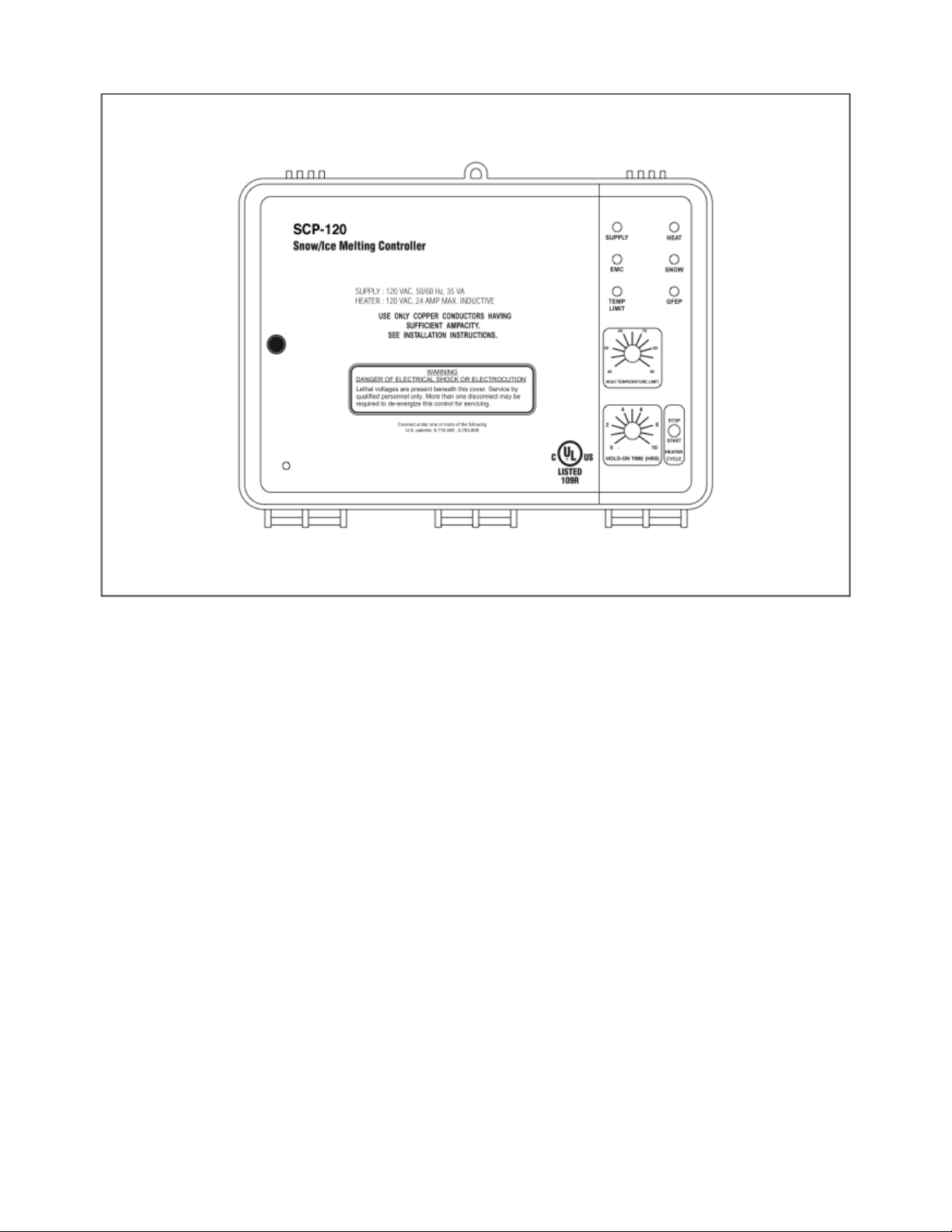
Figure 2: SCP-120 front
panel detail
RCO Remote Control Unit
The RCO Remote Control Unit is used with the SCP-120. It adds remote control and status
display to the SCP-120 control at a location convenient to personnel capable of observing snow
melting system operation.
Snow, slush or ice, either alone or in combination, must contact at least one sensor to start
melting. Heater operation continues until all sensors are dry. Depending on the rate of fall, snow
density, wind velocity, and other factors, heater operation must continue for a period of time after the
last sensor dries off. Slush tracked by vehicle and pedestrian traffi c along with blowing and drifting
snow are problems that are hard to predict.
The cycle timer in the SCP-120 begins when the last sensor dries off and continues for an
adjustable period of up to 10 hours to keep the heaters operational until the pavement is completely
dry. Otherwise, residual water could re-freeze and create a hazardous condition.
The RCO provides a two, four, six or eight hour CYCLE TIME adjustment that is independent of the
cycle time in the SCP-120. This allows treatment of the condition requiring an additional heater cycle
as the exception rather than the rule in order to minimize energy use.
Page 6

Operating the HEATER CYCLE switch operates heaters for the CYCLE TIME which is normally set to 2 hours. Operating the HEATER CYCLE switch during the cycle time stops the timer. If
the pavement or ambient temperature exceeds the SCP-120 HIGH LIMIT TEMPERATURE setting,
the heater duty cycle is reduced or disabled to prevent overheating.
Status indicators include SUPPLY and HEAT. These perform the same functions as those on
the SCP-120 front panel.
Figure 5 shows the RCO layout.
SPECIFICATIONS
All Specifi cations apply to SCP-120
General
Area of use
Approvals
Enclosure
Protection
Cover attachment
Entries
Material
Mounting
Nonhazardous locations
NEMA 3R
Hinged polycarbonate cover, lockable
SCM120: 3 × 1-1/16" entries (120 VAC Single Phase ONLY
Polycarbonate
Wall mounted
Figure 5: RCO
Page 7

Control
Supply
Load
Contact type
Maximum Ratings
Heater hold-on timer
System test
Snow/Ice Sensors
Sensor type
Circuit type
Lead length
High Limit Sensor
Adjustment range
Dead band
Sensor type
Circuit type
Lead type
SCP-120: ETI PN 22470: 120 VAC, 50/60 Hz, 35 VA
SCP-120: ETI PN 22470: 120 VAC, 24 amp max. inductive
ETI PN 22471: 208-240 VAC, 24 amp max. inductive
SCP-120: Form C
SCP-120: Voltage: 120VAC
Current: 24 amps
0 to 10 hours; actuated by snow stopping or toggle switch
Switch toggles the heater contact on and off. If temperature
exceeds high limit, heater cycles to prevent damage.
Up to 6 sensors from the AIR-SS product family
NEC Class 2
Up to 500’ (152m) using 18 AWG 2-wire jacketed cable Up to
1,000’ (304m) using 12 AWG 2-wire jacketed cable
40°F to 90°F (4°C to 32°C)
1°F (0.6°C)
Thermistor network
NEC Class 2
Up to 500’ (152m) using 18 AWG 2-wire jacketed cable Up to
1,000’ (304m) using 12 AWG 2-wire jacketed cable
Energy Management Computer
(EMC) Interface
Inputs
Outputs
Environmental
Operating temperature
Storage temperature
OVERRIDE ON (10 ma dry switch contact)
OVERRIDE OFF (10 ma dry switch contact)
SUPPLY (10 ma dry switch contact) SNOW (10 ma dry switch
contact) HEAT (10 ma dry switch contact) HIGH TEMP (10 ma
dry switch contact) ALARM (10 ma dry switch contact)
–40°F to 160°F (–40°C to 71°C)
–50°F to 180°F (–45°C to 82°C)
Page 8

OPERATION
SCP-120
The snow melting system can be monitored and controlled either locally from the SCP-120 itself
or from two remote locations including:
• RCO Remote Control Unit
• BEMC
Local Control from the SCP-120
Indicators:
• SUPPLY (green) shows that power is present.
• SNOW (yellow) shows that there is a snow/ice signal originating from at least one of the sensors attached to the system.
• HEAT (yellow) shows that there is a call for heat. This happens during snow and for the holdon time thereafter or when the heater cycle switch is operated.
• EMC (yellow) shows that the interfaced Energy Management Computer is presently overriding
local system control.
• TEMP LIMIT (red) shows that either the pavement temperature is above the set HIGH TEMPERATURE LIMIT and there is a call for HEAT or the ambient air temperature is above the set HIGH
TEMPERATURE LIMIT. The SCP-120 can be confi gured to monitor slab temperature or ambient air
temperature but not both.
Adjustments:
• HOLD-ON TIME adjustment sets the time that heaters operate after snow stops. Doing this is
necessary to make certain the pavement dries before heating ceases. This prevents refreezing. Try
an initial setting of 3-5 hours. Increase, if necessary. Reduce with care since energy savings are being traded for an increased likelihood of refreezing.
• HIGH-LIMIT TEMPERATURE adjustment sets the maximum deicing temperature.
Switches:
• HEATER CYCLE switch momentarily toggled down will start a manual heater cycle for the set
HOLD-ON TIME or restart the HEATER CYCLE if on was already in progress. Momentarily toggled
up will cancel a heater cycle if one is in progress.
Remote Control from the RCO
Indicators:
• SUPPLY (green) shows that power is present.
• HEAT (yellow) shows that there is a call for heat. This happens during snow and for the holdon time thereafter or when the heater cycle switch is operated.
Adjustments:
• CYCLE TIME adjustment sets the time heaters will operate when HEATER CYCLE switch is
momentarily depressed at the RCO.
Page 9

Switches:
• HEATER CYCLE switch momentarily depressed will start a manual heater cycle for the set
CYCLE TIME. Momentarily depressed while heaters are being operated by a hold-on timer or during manual heater cycle will end the heater cycle. Heater operation during snow conditions cannot be
canceled in this manner.
Remote Control from the EMC Interface
Please see the EMC section of the manual for interface details.
Energy Management Computer (EMC) Interface
The SCP-120 Series provides an EMC interface to communicate with the EMC of building automation systems. The EMC interface provides 10 mA dry switch contacts for communicating status to
the EMC or starting or stopping the system from the EMC.
EMC interface outputs:
• Output Common
• HEAT indicates that there is a call for heat. This happens during snow and for the hold-on time
thereafter or when the heater cycle switch is operated.
• SNOW indicates that there is a snow/ice signal originating from AIR-SS sensor attached to the
system.
• ALARM
• SUPPLY indicates that power is present.
• TEMP LIMIT indicates that either the pavement temperature is above
the set HIGH TEMPERATURE LIMIT and there is a call for HEAT or the ambient air temperature is
above the set HIGH TEMERATURE LIMIT. An SCP-120 Series control can be confi gured to monitor
slab temperature or ambient air temperature but not both.
EMC interface inputs:
• OVERRIDE ON can be used to override an attached SCP-120 control in order to turn heaters
on. A normal contact closure will turn on heaters until operation is cancelled. If the EMC cycles the
OVERIDE ON relay on and off again within more than 32 milliseconds but less than 300 milliseconds
the attached APS “C” Series control will begin a manual heater cycle and run for the HOLD-ON TIME
set at the panel.
• OVERRIDE OFF can be used to override an attached SCP-120 control in order to turn heaters off. A normal contact closure will turn off heaters. If the EMC cycles the OVERIDE OFF relay on
and off again within more than 32 milliseconds but less than 300 milliseconds the attached SCP-120
control will end a manual heater cycle.
Page 10
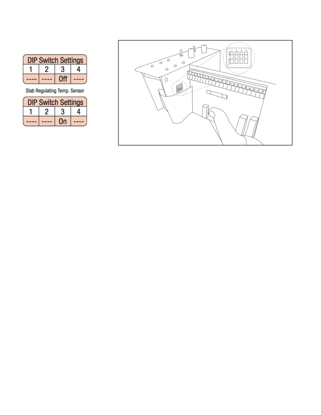
DIP Switch Settings HLT
GF disabled
Figure 8: DIP Switch Setting
for High Limit Sensor
Installation
Confi guring the High Limit Sensor
Dip Switch pin 3 is used to set the high limit sensor op-
eration to one of two possible operational modes:
• OFF sets the high limit sensor as a slab regulating temperature sensor.
• ON sets the high limit sensor as an ambient air sensor.
OFF is the factory default.
Index 8 shows how to confi gure the high limit sensor mode at
the DIP switch.
Factory Use Only
DIP switch pin 4 is for factory use only. The use of pin 4
except by authorized personnel may lead to improper operation
of the SCP-120
Bypassing the High Limit Temperature Sensor
If, for any reason, you need to operate the system without the High Limit Temperature Sensor (for trouble shooting or
while waiting for a replacement sensor) you can temporarily replace the sensor with a 470K resistor. The resistor will allow the
system to run as if the sensed temperature was 40°F (4.4°C).
Refer to Figure 23 for placement of resistor.
Page 11
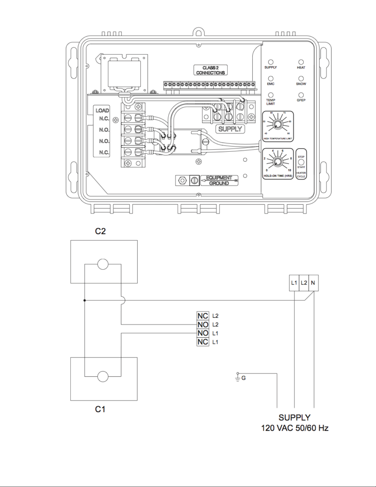
Supply
Figure 10: 120 VAC SCP-120 Operating two electrically held contactors
Page 12
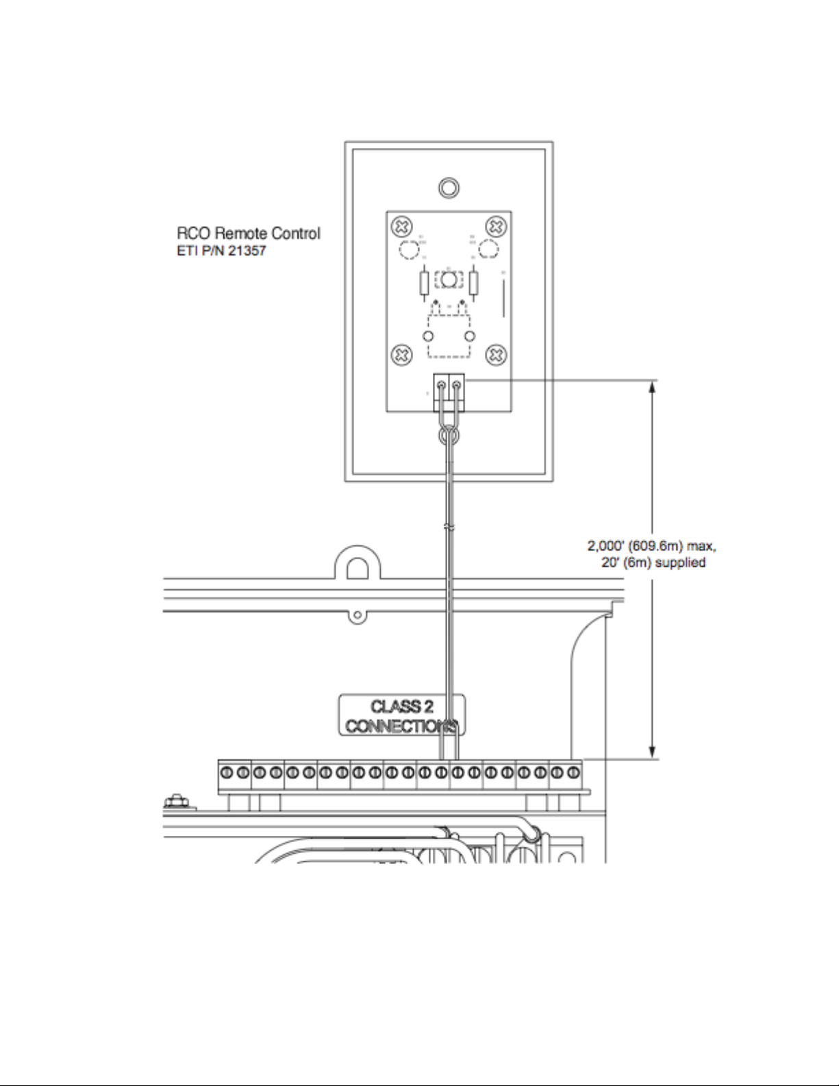
22 21 20 19 18 17 16 15 14 13 12 11 10 9 8 7 6 5 4 3 2 1
Figure 16: SCP-120 & RCO remote connection
Page 13
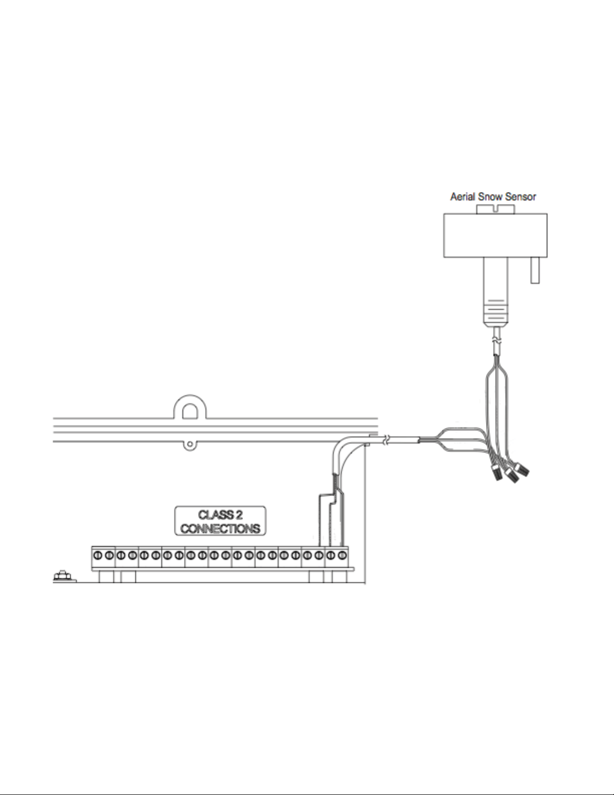
Red
Black
White
AIR-SS
Red
Black
White
22 21 20 19 18 17 16 15 14 13 12 11 10 9 8 7 6 5 4 3 2 1
Figure 19: SCP-120 Sensor Connections
Page 14

Figure 20: SCP-120 EMC connections
Page 15
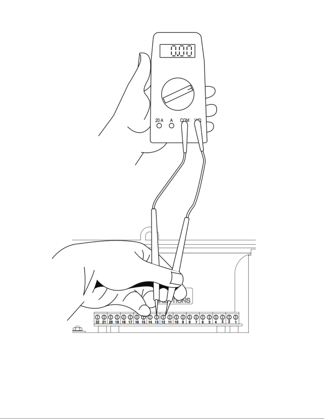
Figure 21: SCP-120 Electrician’s DVM
Page 16

Figure 22: SCP-120 (Slab or Ambient High Limit Sensor)
95-107 ohms (on 200k scale of ohms meter) Thermistor connections
Page 17

Contactor Connections
Contactor Connection
Number
1 Sensor Connection (White Wire)
2 Sensor Connection (Black Wire)
3 Sensor Connection (Red wire)
4 Satellite Panel Connection
5 Satellite Panel Connection
6 Satellite Panel Connection
7 Satellite Panel Connection
8 RCO Connection
9 RCO Connection
10 Thermistor Connection
11 Thermistor Connection
12 Electrician’s DVM
13 Electrician’s DVM
14 Output Common
15 Heat
16 Snow
17 Alarm
18 Supply
19 High Temperature Limit
20 Override On
21 Override Off
22 Close Override On/Off Circuit
Page 18

24/7 Installation Support • Lifetime Technical Assistance • Free Design Service • www.WarmlyYours.com • (800) 875-5285
APS-3C AUTOMATIC CONTROLLER
WIRING TO RELAY (120V)
LNR (Relay Panel) with
2-Pole relays (120V Coils)
APS-3C Automatic Snow Controller (120V)
L
N
Inputs for 120V
Hot Leg
Neutral
Neutral
120V
15 Amp
Breaker
Hot (L1)
Page 19

APS-3C AUTOMATIC CONTROLLER
WIRING TO SENSORS & RCU
(CLASS 2 CONNECTIONS)
Thermistor probe type
sensor (mounts in metal
conduit within the slab
between two passes of
heater cable)
Optional Device
RCU-3 Unit
CIT-1 Aerial Snow Sensor
Red
Black
White
2
19
20 1821
17
16
15
14
1213
1011
89
6
7
5
3
4
1
APS-3C Automatic Controller Panel
10272-A 1/11
24/7 Installation Support • Lifetime Technical Assistance • Free Design Service • www.WarmlyYours.com • (800) 875-5285
 Loading...