

Page 1

23735
Rev. B
06/14
(800) 234-4239
http: www.networketi.com
Environmental Technology, Inc.
1 of 30
Snow Switch® Model PD Pro
Instruction Manual
This manual refers to the Snow Switch® Model PD Pro control panel manufactured
since October 31, 2013, which uses a universal (100 – 277 VAC; 50/60 Hz) power supply.
Older units use a voltage-specific power supply and have different wiring configurations.
SAFETY INFORMATION AND WARNINGS
Abnormal Odor or Smoke
In the event of smoke or a burning or abnormal odor, immediately interrupt power to the unit by
unplugging the unit or by turning off the circuit breaker protecting the unit.
Electrical Shock / Fire Hazard
Even when the heat tapes are disconnected, as long as the circuit breaker is on and power is running to
the unit, voltage is still being applied to the yellow heat tape leads. Therefore, never touch the ends of the
yellow leads or let the two leads touch each other. Do not let the two yellow heat tape leads contact any
component inside the unit.
Any installation involving electric heater wiring must be grounded to earth to protect against shock and
fire hazard. Suitable ground fault detection and interrupting systems must be in use at all times to reduce
shock and fire hazard and to protect equipment.
Electric wiring to heating elements must be installed in accordance with National Electrical Code (NEC)
requirements and all other local and applicable electrical codes and any third party standards. Follow the
installation instructions contained herein and those provided by the heater manufacturer.
Use a GFEP (Ground Fault Equipment Protection) circuit breaker on each branch circuit connected to the
ice melting system. Clearly label each circuit breaker with its function. This is vitally important when
there is more than a single point of disconnect.
Size the circuit breaker in accordance with the size of the expected load. The maximum current load for
the PD Pro is 30 Amp resistive. The PD Pro often serves as a pilot duty relay for operating high current
single- or three-phase contactors in residential or light commercial applications. This product is intended
for use in residential or light commercial applications. For larger or more critical installations, the “APS”
Series of control panels from Environmental Technology, Inc., provides a cost-effective solution offering
enhanced system design and performance features.
Make certain that the heater shield is properly grounded. Failure to do so may result in damage to the
equipment or fire.
Following installation, and prior to beginning system operation, refer to and perform the Post-Installation
Tests described in this manual.
Page 2

23735
Rev. B
06/14
(800) 234-4239
http: www.networketi.com
Environmental Technology, Inc.
2 of 30
READING
Check heat tape manufacturer’s documentation.)
SYSTEM CURRENT (Amps)
system breaker sizing)
Snow Switch® Model PD Pro
Instruction Manual
PRODUCT TESTING RECORD
Use this page to record the results of the testing procedures in this manual. Specifically, these
are a mega-ohm test following installation of the heat tape, a post-installation test of the control
box, and a post-installation test of the system sensor(s). This record will be a useful resource
throughout the life of the product.
MEGA-OHM TESTING (Page 10)
(Follow heat tape manufacturer’s recommendations or, if not available,
use a 500 VDC mega-ohm meter on the heat tape.)
TEST
DATE
TEST
DATE
AMBIENT
TEMPERATURE
POST-INSTALLATION CONTROL TESTING (Page 15)
(Use a voltmeter or clamp-on amp meter on either yellow control lead.)
SUPPLY VOLTAGE (Volts)
AMBIENT
TEMPERATURE
POST-INSTALLATION SENSOR TESTING (Page 16)
(Use a voltmeter on the leads indicated.)
If heat tape is disconnected.
(Use voltmeter.)
(Target: faceplate voltage)
Sensor Supply Voltage Sensor Control Voltage
(Target: 20 MΩ or greater;
If heat tape is not disconnected.
(Target: should be based on heat
consult heat tape supplier;
reading must be less than
faceplate amps and
(Use amp meter.)
tape used,
TEST
DATE
AMBIENT
TEMPERATURE
Red to Black White to Black
Warm & Dry
(Target: 23 – 28 VDC)
(Target:
22 – 28 VDC)
Cold & Wet
(Target: less than
2 VDC)
Page 3

23735
Rev. B
06/14
(800) 234-4239
http: www.networketi.com
Environmental Technology, Inc.
3 of 30
Snow Switch® Model PD Pro
Instruction Manual
TABLE OF CONTENTS
SECTION PAGE
Safety Information and Warnings --------------------------------------------------------------- 1
Product Testing Record ------------------------------------------------------------------------- 2
Unpacking the Unit ----------------------------------------------------------------------------- 4
Inventory ---------------------------------------------------------------------------------------- 5
Product Description ----------------------------------------------------------------------------- 5
Selecting the Proper Sensor -------------------------------------------------------------------- 6
Available Optional Components ----------------------------------------------------------------- 6
Installing the Control ---------------------------------------------------------------------------- 8
Preparation and System Set-Up ---------------------------------------------------------------- 9
System Schematic Diagrams ----------------------------------------------------------------- 11
Post-Installation Testing ---------------------------------------------------------------------- 14
Operation -------------------------------------------------------------------------------------- 18
Optional Remote Control Operation ----------------------------------------------------------- 21
Maintenance ---------------------------------------------------------------------------------- 22
Troubleshooting ------------------------------------------------------------------------------ 23
Heater Connection ------------------------------------------------------------------------------ 28
Specifications --------------------------------------------------------------------------------- 29
Ordering Information -------------------------------------------------------------------------- 30
Page 4

23735
Rev. B
06/14
(800) 234-4239
http: www.networketi.com
Environmental Technology, Inc.
4 of 30
Snow Switch® Model PD Pro
Instruction Manual
UNPACKING THE UNIT
Immediately upon receipt, inspect the container and packing material for any noticeable damage.
Unpack the unit, taking care not to damage the packing materials. Save the shipping container
and related materials until normal operation has been established. If the unit must be returned,
take care to ensure that it is repackaged as it was received.
As soon as the unit arrives at your facility, inspect it for mechanical damage. If any of the
following problems is found, contact Environmental Technology, Inc., Customer Service
immediately:
• contents incomplete or incorrect;
• internal or external mechanical damage; or
• defective operation.
ETI Customer Service is available between 8:00 a.m. and 5:00 p.m. Eastern Time at (574) 2331202 or (800) 234-4239. In the event of shipping damage, keep the packing materials for
inspection by the carrier.
RETURNS AND REPLACEMENT PART PURCHASES
Equipment cannot be returned for credit once it has been installed. ETI will repair or replace
faulty equipment under warranty. Prior to removal of equipment for warranty return, please
contact ETI Technical Support at (800) 234-4239 for troubleshooting assistance.
Before returning a unit to Environmental Technology, Inc., obtain a Return Merchandise
Authorization from our Customer Service Department, available between 8:00 a.m. and 5:00 p.m.
Eastern Time at (574) 233-1202 or (800) 234-4239. If possible, use the original container and
packing materials when packing the unit for shipment. It is important to mark the Return
Merchandise Authorization clearly on the outside of the shipping container so that it may be
correctly processed upon receipt at Environmental Technology.
For more information about replacement parts or for a replacement Data Sheet or Manual, please
visit http://www.networketi.com/.
Page 5

23735
Rev. B
06/14
(800) 234-4239
http: www.networketi.com
Environmental Technology, Inc.
5 of 30
Snow Switch® Model PD Pro
Instruction Manual
INVENTORY
Using the information below, verify that the shipping package contains all of the parts listed.
Notify Environmental Technology, Inc., Customer Service immediately if there are any
discrepancies. Environmental Technology, Inc. Customer Service is available between the hours
of 8:00 a.m. and 5:00 p.m. Eastern Time at (574) 233-1202 or (800) 234-4239.
Item Number Item Description
1 PD Pro
2 Accessory Kit
3 PD Pro Installation Sheet
4
PD Pro Instruction Operation Manual
(this document)
Depending on the specifics of your order, there will also be up to two sensors included with the
system, as well. These will be either the CIT–1 aerial-mount sensor, the GIT–1 gutter ice sensor,
or the SIT
–6E pavement-mount sensor.
PRODUCT DESCRIPTION
The Snow Switch model PD Pro snow and ice control, when used with up to two compatible
sensors, automatically controls snow and ice melting heaters for minimal energy costs.
Applications include pavement, sidewalk, loading dock, roof, gutter, and down spout snow/ice
melting in commercial and residential environments. The PD Pro control is powered from
operating voltages of from 100 to 277 VAC and is rated for 7 amps inductive load. Additionally,
the PD Pro is rated for 30 amps resistive load.
The PD Pro control is housed in an environmentally-sheltered IP 66, NEMA 4X weather-resistant
enclosure to provide several installation options.
Features and Benefits
• Compatible with standard CIT–1, GIT–1, and SIT–6E sensors
• Two sensor input to allow for application specific sensor combination such as:
o A CIT–1 aerial sensor and a GIT–1 gutter sensor for roof and gutter deicing
o A CIT–1 aerial sensor and SIT–6E pavement-mounted sensor for snow melting
• Adjustable 0 – 8 hour hold-on time
• Compatible with the RCU–3 remote control
Page 6

23735
Rev. B
06/14
(800) 234-4239
http: www.networketi.com
Environmental Technology, Inc.
6 of 30
One or two CIT–1 Sensors
One GIT–1 Sensor
One GIT–1 and one CIT–1 Sensor
One SIT–6E Sensor and one CIT–1 Sensor
Snow Switch® Model PD Pro
Instruction Manual
• Durable IP66, NEMA 4X enclosure
• UL Listed to UL 873 Temperature-Indicating and -Regulating Equipment
SELECTING THE PROPER SENSOR
The Snow Switch model PD Pro snow and ice control is designed for use with up to two
compatible sensors. Compatible sensors include the CIT–1, GIT–1, and SIT–6E snow and ice
melting sensors. These sensors have provided the industry’s most versatile and cost effective
snow melting control when used with Environmental Technology control panels. Sensors should
be selected to best suit the intended application.
The CIT–1, GIT–1, and SIT–6E snow and ice melting sensors combine to reliably detect snow and
ice in gutter and pavement applications. The CIT–1 sensor may be paired with either the GIT–1
sensor for gutter applications or the SIT–6E sensor for pavement applications. These sensors
detect precipitation as snow at temperatures below 38°F (3.3°C). Control panels are signaled
only if moisture occurs below this temperature, saving energy and ensuring reliable melting.
Table 1 below presents the recommended sensor combinations for use with the PD Pro snow
and ice control.
Table 1. RECOMMENDED SENSOR COMBINATIONS.
For more complete information regarding the sensors and their individual capabilities, refer to the
Products link on the Environmental Technology website, http://www.networketi.com.
AVAILABLE OPTIONAL COMPONENTS
Prior to installation and set-up, it is first useful to discuss two important optional components
available for the Snow Switch PD Pro system. The first of these optional components is a
Remote Control Unit, RCU–3 (Part Number 21357), which allows remote operation of the system
away from the control box. The second optional component is a Temperature Sensor Assembly
(Part Number 19272) which regulates the heating cycle to make it more efficient. Neither of
these optional components comes with the basic system so either or both of them must be
ordered separately and installed along with the system, not only to facilitate their installation but
also to optimize their performance.
Page 7

23735
Rev. B
06/14
(800) 234-4239
http: www.networketi.com
Environmental Technology, Inc.
7 of 30
Order Number
Description
21357
Optional Remote Control Unit RCU–3
19272
Optional Temperature Sensor Assembly
Snow Switch® Model PD Pro
Instruction Manual
With the Remote Control Unit, RCU–3, the operator is able to access the full range of system
functions and controls from a second location. With the RCU–3, the operator can manually set
the Cycle Time, equivalent to the Hold-On Time setting on the face of the unit itself, or manually
initiate or terminate a heating cycle. The capability for remote operation is especially useful if
the control box is installed either outside or in a location of the building not easily or readily
accessible by office personnel who may well be in a better location than building maintenance
personnel to assess the need to melt ice or snow from walkways or parking areas.
Also available for the PD Pro system is an optional temperature sensor assembly which senses
the temperature at the cable end and regulates the Hold-On Time period once precipitation has
ended and the call for heat has passed. Installed with the cable end placed at or near the heat
tape, the optional temperature sensor assembly or thermistor is a high-temperature shut-off and
regulates the Hold-On Time period by automatically suspending an active heating cycle if at any
time during that cycle, the temperature at the sensor end rises to above 45°F. Then, if, during
the Hold-On Time period, the temperature drops to below 44°F, the heating cycle will resume
automatically and continue until the end of the Hold-On Time period as set on the face of the
unit. This not only lowers system operating costs but also protects the heat tape from overheating.
As the placement of the RCU–3 remote control unit is a key factor in the overall configuration of,
as well as customer satisfaction with, the PD Pro system, it is important that it be installed as
part of the system initially. Similarly, as the temperature sensor assembly monitors the
temperature at the point of the cable end to keep the heat tape from over-heating, so it is
necessary, for best results, to lay the temperature sensor at the same time as the heat tape to
ensure proper placement and routing. It is not recommended to try and retrofit either of these
optional assemblies once the system is already installed and operational.
To ensure proper installation and to facilitate placement, wiring, routing, and function of either or
both the RCU–3 or the temperature sensor, it is strongly advised and suggested that these
assemblies, whether together or individually, be installed with the system initially rather than
retrofitted afterwards. Use the information below to order either or both of these important
optional components.
To order either or both of these optional components for your system, contact the Environmental
Technology Sales Department between the hours of 8:00 a.m. and 5:00 p.m. Eastern Time at
(574) 233-1202 or (800) 234-4239.
Page 8
23735
Rev. B
06/14
(800) 234-4239
http: www.networketi.com
Environmental Technology, Inc.
8 of 30
Top
Right Side View
Snow Switch® Model PD Pro
Instruction Manual
INSTALLING THE CONTROL
Install this unit in compliance with National Electrical Code (NEC) standards, as well as all other
local and applicable electrical codes for your area. Prior to beginning installation, make sure that
the facility has properly sized electric service and breaker. For additional information regarding
electrical ratings and facility power requirements, refer to the Specifications section of this
manual.
This unit is intended for wall mount installation only. The wall used for the installation should be
capable of supporting four times the weight of the unit, or about 20 pounds. Install the unit
directly to a solid, stable surface. The IP 66, NEMA 4X weather-resistant enclosure can be
installed either inside or outside.
Internal connections for any optional remote control unit or system sensor(s) will be made in the
next section.
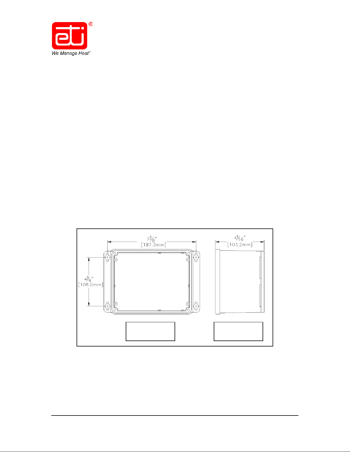
The dimensions shown in the Top View of Figure 1 below are for the mounting hole location
footprint and run from centerline to centerline of the four slotted mounting holes. The dimension
shown in the Right Side View of Figure 1 is from the bottom of the enclosure to the top of the
clear plastic lid and shows the distance that the unit will protrude from the mounting surface.
Figure 1. PD Pro MOUNTING HOLE FOOTPRINT.
View
Page 9

23735
Rev. B
06/14
(800) 234-4239
http: www.networketi.com
Environmental Technology, Inc.
9 of 30
Snow Switch® Model PD Pro
Instruction Manual
To install the control box, perform the steps below.
NOTE
During installation, leave all mounting hardware loose enough to allow for slight adjustments to
component placement. Once all components and the front panel and clear plastic cover have
been installed, then, as the final step in installation, fully tighten all mounting hardware and
weather-tight fittings. Make sure all connections and fittings are snug, air-tight, and water-tight.
1. Use the box as a template to determine the mounting hole footprint pattern. Hold the
unit up against the wall onto which it will be mounted, with the mounting blocks against
the wall, then mark the wall at the locations of the slotted mounting holes to determine
the location of the mounting holes on the wall.
2. As desired, to hold the box in place during the installation process, you may loosely
install one or both of the top mounting bolts as the remaining holes are marked. To
ensure accurate and level installation, however, do not fully tighten any of the mounting
hardware until all hardware has been started.
3. Once the four mounting holes have been located and marked, install the box to the wall
using properly sized mounting hardware. Be sure to use mounting hardware appropriate
for the job, heavy-duty and long enough to fasten the unit securely to the mounting
surface. Make sure to use all four mounting holes. Because conduit will also be
installed to protect the cables running from the control box, install the box, but leave the
mounting hardware loose enough to work the conduit into place. The conduit will be
installed later in this process, at which time all mounting hardware will be securely
tightened.
PREPARATION AND SYSTEM SET-UP
Install the conduit, system sensor(s) and sensor cables, heater cables, and power cable. Refer to
Figures 2 and 3, as well as Table 2. Remove the clear plastic unit cover and face plate to access
the inside of the unit. These will be replaced at the end of the installation process. A postinstallation test will be performed in the next section to verify proper function.
NOTE
During installation, leave all mounting hardware loose enough to allow for slight adjustments to
component placement. Once all components and the front panel and clear plastic cover have
been installed, then, as the final step in installation, fully tighten all mounting hardware and
weather-tight fittings. Make sure all connections and fittings are snug, air-tight, and water-tight.
Page 10

23735
Rev. B
06/14
(800) 234-4239
http: www.networketi.com
Environmental Technology, Inc.
10 of 30
Snow Switch® Model PD Pro
Instruction Manual
INSTALLING THE CONDUIT
Only UL listed, Type 4X, raintight conduit hubs and cable glands are to be used. The hub is to be
connected to the conduit of a rigid conduit system before the hub is connected to the enclosure.
Select, measure, cut, and install the conduit in accordance with all National Electrical Code (NEC)
requirements, all local and applicable building and electrical codes, as well as the
manufacturer’s instructions. Ensure a sealed, watertight installation.
INSTALLING THE SENSOR(S)
Refer to the enclosed Installation Sheet(s) and Instruction Manual(s) for sensor installation and
operating instructions.
INSTALLING THE SENSOR CABLES
Route the sensor cables through the weather-tight connection ports on the right side of the unit,
then connect the red, black, and white leads to the front panel PC board terminal block J1
terminals. If using two sensors in the system, even if they are of the same type, it does not
matter which one is wired into which set of terminal blocks, upper or lower. After connecting the
red, black, and white leads, push a little more of the cable into the connection port to create a
little more slack to relieve some of the tension from the wires at the point of the terminal strip,
then fully tighten the weather-tight connection to secure the cable in place. If installing an
extension onto the sensor cable(s), a junction box is required in accordance with applicable code.
INSTALLING THE HEATER CABLES
Lay-out, configure, and install the system heater cables in accordance with National Electrical
Code (NEC) and manufacturers’ requirements, as well as all other local and applicable building
and electrical codes. Make sure to properly seal and waterproof all cable runs. If using a SIT–6E
pavement-mount sensor, position the heater cabling so it does not interfere with the sensor
wiring.
Upon conclusion of heater cable installation, perform a mega-Ohm or “megger” test on the
heater cables as directed by the heater cable manufacturer. Record the results on page 2 of this
manual and retain for future reference.
INSTALLING THE OPTIONAL COMPONENTS
Route the remote control (RCU–3) cables through the conduit then into the enclosure. Connect
the remote cables to the front panel PC board terminal block J1 terminals labeled REMOTE.
Route the optional temperature sensor assembly wiring through the same conduit as the RCU–3
cable then into the enclosure. Connect the temperature sensor assembly cables to the front
panel PC board terminal block J1 terminals labeled AUX.
Page 11

23735
Rev. B
06/14
(800) 234-4239
http: www.networketi.com
Environmental Technology, Inc.
11 of 30
RCU–3 &
(Input Power &
Ground)
CIT–1
Sensor
100 – 277 VAC
30 Amp Max.
Input Power
To Heater Cable
GIT–1 Sensor
Snow Switch® Model PD Pro
Instruction Manual
INSTALLING THE POWER CABLE
With the circuit breaker off, install the power cable. As shown in the wiring charts, the power
cable is provided by the customer. Size the cable for a 30 Amp maximum load. Run the cable
through conduit and connect the leads to the control box wiring. The line is black, neutral is
white, and ground is green. The unit has no power switch so remember that power is running to
the system as soon as power is applied.
SYSTEM SCHEMATIC DIAGRAMS
This manual refers to the Snow Switch® Model PD Pro control panel manufactured
since October 31, 2013, which uses a universal (100 – 277 VAC; 50/60 Hz) power supply.
Older units use a voltage-specific power supply and have different wiring configurations.
Figure 2 is a schematic diagram of an entire PD Pro system, including the available optional
components.
Heater Load 1/Yellow
Heater Load 2/Yellow
Heater Ground
(Shield)/Green
Line/Black
Neutral/White
Ground/Green
Figure 2. REPRESENTATIVE PD Pro SYSTEM SCHEMATIC
Optional
Temp.
Sensor
50/60 Hz
Page 12

23735
Rev. B
06/14
(800) 234-4239
http: www.networketi.com
Environmental Technology, Inc.
12 of 30
SENSOR Wiring
#18 AWG jacketed, 3-conductor
Wire Lead
Connect To:
Line 1
Black
Line 2 / Neutral
White
Ground
Green
Heater Load 1
Yellow
Heater Load 2
Yellow
Heater Ground (Shield)
Green
SIT–6E Sensor
Heat Tape
Optional
Sensor
(Cables Inside
Conduit)
Snow Switch® Model PD Pro
Instruction Manual
POWER Cable (provided by customer)
Size for 30 Amp maximum load
HEATER Cable (provided by customer)
REMOTE Wiring
TEMPERATURE SENSOR ASSEMBLY Wiring
Size to system load
#22 AWG jacketed, 2-conductor
#22 AWG jacketed, 2-conductor
INPUT Power
(provided by customer)
OUTPUT To Heater
(provided by customer)
Table 2. CABLE RATINGS AND CONNECTIONS.
A representative schematic diagram of an SIT–6E pavement sensor installation is shown below in
Figure 3. Note how the heat tape and other components do not cross.
Temperature
Figure 3. REPRESENTATIVE SIT–6E PAVEMENT INSTALLATION
Page 13

23735
Rev. B
06/14
(800) 234-4239
http: www.networketi.com
Environmental Technology, Inc.
13 of 30
Cable Connector
Terminal block
1 Amp Fuse
Fuse LED
Sensor Cables (It
Optional
Optional Remote
Refer to Figure 4 for useful information regarding the front panel PC board.
Receptacle
(Note the notch
to ensure proper
orientation.)
Snow Switch® Model PD Pro
Figure 4. THE PD Pro FRONT PANEL PC BOARD.
Instruction Manual
J1 with terminals
labeled for
system cables
and wiring.
Temperature
Sensor Wiring
Control
(RCU–3) Wiring
does not matter
which of the
sensors is wired
into which set of
terminals.)
Page 14

23735
Rev. B
06/14
(800) 234-4239
http: www.networketi.com
Environmental Technology, Inc.
14 of 30
Snow Switch® Model PD Pro
Instruction Manual
POST-INSTALLATION TESTING
Installation errors cause the majority of system problems. Therefore, thoroughly check the
system before placing it into service. Simple electrical tests and visual inspection can identify
any wiring errors, as well as improper waterproofing. Visually inspect for proper wiring and
waterproofing, making sure that all box joints are sealed and that all wiring is properly
terminated.
In performing the post-installation test procedure as described below, the heat tape will activate,
even if only for a brief time, so that system performance can be accurately simulated and
measured. For that reason, and depending specifically on the ambient temperature or general
conditions in which the system is being installed, it is recommended to continuously and
carefully monitor the system and its components during the entire testing process. High
temperatures can cause damage to asphalt and similar paving materials. Never leave the site
during testing. Never leave the system unattended during testing. If fire or smoke or an
abnormal odor is observed during testing, shut off power to the system and suspend the test.
To most accurately simulate and measure system performance, leave the heat tape connected to
the control during testing and use a clamp-on amp meter as directed in this procedure. Using
the clamp-on amp meter clamped around the wires prevents the operator from having to touch
bare or exposed metal or wiring and also keeps the operator from having to break the circuit, all
while still allowing the accurate simulation and testing of the system, including the Ground Fault
Equipment Protection circuitry, if your system is so equipped.
It is the responsibility of the on-site installer to assess the overall safety concerns at the site and
to disconnect the heat tape, as necessary or desired, whether before or during this test, as well
as to re-establish those wiring connections at the conclusion of this procedure.
WARNING
Even when the heat tapes are disconnected, as long as the circuit breaker is on and power is
running to the unit, voltage is still being applied to the yellow heat tape leads. Therefore, never
touch the ends of the yellow leads or let the two leads touch each other. Do not let the two
yellow heat tape leads contact any component inside the unit.
This procedure requires a clamp-on amp meter or voltmeter. Make sure the gutter and
downspout are both dry before testing the GIT–1 sensor. Record test results in the appropriate
section on page 2 of this manual for future reference.
Page 15

23735
Rev. B
06/14
(800) 234-4239
http: www.networketi.com
Environmental Technology, Inc.
15 of 30
Snow Switch® Model PD Pro
Instruction Manual
CONTROL TESTING
1. Remove system power. There may be two or more points of disconnect.
2. Open the clear plastic cover and remove faceplate from the unit. Retain all parts and
mounting hardware. If the heaters have been disconnected for testing, using a
voltmeter, measure the voltage across the two yellow leads. If the heaters have not been
removed tor testing, using a clamp-on amp meter, measure the current through the
yellow lead.
3. Restore power to the unit. After a brief initialization routine, the SUPPLY LED should be
on, but no other LEDs. Once initialization is complete, the amp meter or voltmeter
should read 0.
4. With power still running to the unit, turn up the Hold-On Time dial to a setting higher than
0, then press the Heater Cycle button. The HEAT LED should come on and the amp
meter should show a reading of less than the maximum system load as shown on the
faceplate. The voltage across the yellow leads will match the system voltage. Do not
touch the yellow lead ends.
5. Press the Heater Cycle button again. The HEAT LED will go off and the amp meter
reading should drop back to 0 or the voltage will drop to 0. Record results on page 2 of
this manual.
6. Remove the amp meter or voltmeter. Do not yet re-install the unit front plastic cover or
faceplate.
7. Proceed to sensor testing on the following page.
Page 16

23735
Rev. B
06/14
(800) 234-4239
http: www.networketi.com
Environmental Technology, Inc.
16 of 30
Snow Switch® Model PD Pro
Instruction Manual
CIT–1 AND GIT–1 SENSOR TESTING
The CIT–1 and GIT–1 sensors have two interrelated systems: the temperature sensing system
and the moisture detection system. Complete testing of the sensor involves manipulation of
both. The tools needed for this procedure are a voltmeter and an aerosol circuit cooler (“Freeze
Spray” is preferred) or cup of ice water. The Freeze Spray is available at most electric supply
stores.
Ensure that the moisture sensing grid on the sensor is clean and dry.
Follow the steps below to perform the CIT–1 and GIT–1 sensor post-installation test procedure.
The SIT–6E testing procedure is on the next page.
1. Connect the voltmeter across the black and red leads from the sensor (low-voltage
wiring terminals at the control). Connect the black test lead to the black wire. You
should obtain a reading of 23 to 28 VDC. Now, check the reading across the black and
white sensor leads. You should read 22 to 28 VDC with a warm (above 38°F) and dry
sensor. Both the SNOW LED and HEAT LED should remain off.
2. Cool the temperature probe of the sensor with the Freeze Spray. You should see frost
form on the temperature probe. Alternately, place the temperature probe in ice water.
The SNOW LED and HEAT LED should remain off.
3. Using a moist finger, touch the moisture sensing grid on top of the sensor. Both the
SNOW LED and HEAT LED should come on and the voltage between the white and black
sensor leads should be less than 2 VDC.
4. With the unit cold and the sensing grid moist, allow the unit to warm up to above 38°F.
The SNOW LED should turn off and the HEAT LED should stay on and the voltage should
return to 22 – 28 VDC. Record results on page 2 of this manual.
5. If testing a SIT–6E sensor, proceed to the next section now. If testing is complete, with
unit powered off, restore all wiring connections and re- install the face plate and clear
plastic cover. Set the Hold-On Time control dial to the desired setting.
Page 17

23735
Rev. B
06/14
(800) 234-4239
http: www.networketi.com
Environmental Technology, Inc.
17 of 30
Snow Switch® Model PD Pro
Instruction Manual
SIT–6E SENSOR TESTING
If paving material or other residue adheres to the sensing elements, clean the surface with a
Scotch™ Brite Pad. Avoid using metallic or coarse abrasives or detergents.
Regardless of weather conditions, the functional operation of an installed SIT–6E sensor can be
determined using a digital voltmeter (DVM) and a 10-pound (4.54kg) bag of crushed ice as
described below.
With the DVM set to the 100 VDC range, verify the sensor supply voltage by connecting
1.
the negative (–) test lead to the sensor black wire and the positive (+) test lead to the
sensor red wire. A DVM reading between 23 and 28 VDC is acceptable.
With the negative (–) test lead remaining in place, reconnect the positive (+) test lead to
2.
the sensor white wire and confirm there is 22 to 28 VDC present. Both the HEAT LED
and the SNOW LED should be off.
Place the entire contents of the bag of crushed ice on top of the sensor and allow a time
3.
lapse in excess of 20 minutes before observing that less than 2 VDC is indicated by the
DVM. Depending on ambient conditions, however, this might take only a few minutes, in
which case, that is not a problem. (A nominal temperature below 38°F or 3.3°C must be
detected before the sensor’s normally-open contact is closed. If the sensor surface
temperature was excessive prior to beginning this procedure, it will be necessary to
extend the cool-down time interval by as much as an additional 20 minutes.) Most
importantly, make sure both the HEAT LED and the SNOW LED come on. Record results
on page 2 of this manual.
With satisfactory results, control and sensor pre-operational testing is now complete.
4.
Disconnect and remove all testing devices from the system.
5. Once all post-installation testing is complete and with unit power off, restore all wiring
connections.
6. Re-install the face plate and clear plastic cover onto the control. Set the Hold-On Time
control dial to the desired setting.
Page 18
23735
Rev. B
06/14
(800) 234-4239
http: www.networketi.com
Environmental Technology, Inc.
18 of 30
Operator Controls and
Note the information
Snow Switch® Model PD Pro
Instruction Manual
OPERATION
This section presents operating instructions for the unit and begins with a picture of the front
panel. Refer to Figure 5. Note the system information on the left side of the panel, as well as the
operator controls and indicators located on the right side of the panel. The controls and
indicators are explained in this section.
presented here.
Figure 5. THE PD Pro FRONT PANEL
Note that because the unit has no ON/OFF power switch, power runs to the unit as soon as
facility power is connected to it. For as long as power is running to the unit, the green SUPPLY
LED will always be lit. The unit initiates a heating cycle when the system sensor(s) detect snow
or ice at or below 38°F (3.3°C).
Upon initial Start-Up, all of the LEDs will come on for 2.5 seconds, and then shut off for 2.5
seconds. After this, the device goes into normal operation.
Indicators
Page 19

23735
Rev. B
06/14
(800) 234-4239
http: www.networketi.com
Environmental Technology, Inc.
19 of 30
System sensors currently
Power is running to the
Press to start or cancel a
When the Hold-On Time is set
Heating Cycle is currently in
In this view, the Hold-On Time
Operator controls and indicators are explained below. Refer to Figure 6.
system.
detect precipitation.
at 0, the unit will produce heat
only while the system
sensor(s) detect moisture at or
below 38°F (3.3°C) and for no
longer. For best results, it is
recommended to set the HoldOn Time to approximately 2 to
6 hours so all moisture
completely melts and
evaporates.
SUPPLY The SUPPLY LED lights up and stays lit as long as power is running to the unit, whether
HEAT When the HEAT LED is lit, the unit is currently engaging power to the heater outputs in
SNOW The SNOW LED lights up when any of the sensors detect snow or ice at or below 38°F
Snow Switch® Model PD Pro
Instruction Manual
progress.
is currently set at 0. Rotate
the control knob to the right to
increase the setting or to the
left to decrease the setting.
heating cycle.
Figure 6. PD Pro OPERATOR CONTROLS AND INDICATORS
it is currently in a heating cycle or not.
response to sensor input. The HEAT LED stays on for the duration of the heating cycle.
As desired, press the Heater Cycle button to stop a current heating cycle, unless the
SNOW LED is lit.
(3.3°C) and stays on until the sensors no longer detect snow or ice or the temperature
surpasses 38°F (3.3°C). Note that the Heater Cycle button cannot be used to cancel a
current heating cycle if the SNOW LED is lit.
Page 20

23735
Rev. B
06/14
(800) 234-4239
http: www.networketi.com
Environmental Technology, Inc.
20 of 30
Snow Switch® Model PD Pro
Instruction Manual
SETTING THE HOLD-ON TIME
Heating action begins a few seconds after the sensor detects moisture at or below 38°F (3.3°C).
However, heating action continues even after the sensor no longer detects moisture based on the
Hold-On Time setting. The Hold-On Time control knob allows you to set the length of time the
unit will continue heating even after the sensor no longer detects moisture. This is beneficial
because it typically takes longer for ice to melt than it took to form initially and also because it
keeps moisture from re-freezing before it has fully evaporated. As indicated on the front panel,
the Hold-On Time can be set for anywhere from 0 to 8 hours as indicated by the arrow on the
control knob. Note that if the Hold-On Time control knob is set at 0 (as shown in Figure 5), the
unit will produce heat only for as long as the sensor detects moisture but for no longer. For that
reason and to ensure more effective heating, it is recommended that the Hold-On Time be set up
closer to the mid-way point, corresponding to about 2 to 6 hours.
Set or increase the Hold-On Time as desired by rotating the control knob to the right or
clockwise. Decrease the Hold-On Time setting by rotating the control knob to the left or
counterclockwise. Again, remember that if the Hold-On Time control knob is set at 0, the unit
will produce heat only for as long as the system sensor(s) detect moisture and no longer.
USING THE HEATER CYCLE BUTTON
The Heater Cycle control button allows you to manually initiate a heating cycle regardless of
weather conditions, whether or not the sensor currently detects moisture, and regardless of the
temperature. The Heater Cycle control button also allows the operator to cancel a heating cycle
currently in progress, regardless of the Hold-On Time setting, unless the SNOW LED is on,
indicating the sensor currently detects moisture at or below 38°F (3.3°C). Remember, if you
manually initiate a heating cycle by pressing the Heater Cycle button, that heating cycle will last
for the duration of the current Hold-On Time setting, unless manually cancelled by pressing the
Heater Cycle a second time.
It is not necessary for the Hold-On Time setting on the control box and the Hold-On Time setting
on the RCU to be identical. Note, however, that if a heating cycle is manually started by pressing
the Heater Cycle button on the control box, that the resulting heating cycle will last as long as the
Hold-On Time setting on the control box. Similarly, if a heating cycle is initiated using the RCU,
the resulting heating cycle will last as long as the Hold-On Time setting on the RCU.
Page 21
23735
Rev. B
06/14
(800) 234-4239
http: www.networketi.com
Environmental Technology, Inc.
21 of 30
When “SUPPLY” LED
is lit, power is running
Rotate “CYCLE TIME”
dial to select desired
When “HEAT”
LED is lit, a
heating cycle is
Press “HEATER
CYCLE” button to
initiate or cancel a
When LED is lit, a
Press button to
When LED is lit, power is
Rotate dial to select
Snow Switch® Model PD Pro
Instruction Manual
OPTIONAL REMOTE CONTROL OPERATION
The PD Pro can be operated either “locally” on the face of the unit itself or by using the optional
remote control unit, RCU–3. Refer to Figure 7.
heating cycle is in
progress
running to the system
initiate or cancel a
heating cycle
desired Cycle Time
duration
Figure 7. REMOTE CONTROL UNIT RCU–3.
The RCU Cycle Time control dial moves in discrete increments rather than in a continuous motion
as on the control box. Cycle Time on the RCU applies only to a manual heating cycle initiated at
the RCU, not the Cycle Time setting on the control box. The RCU cannot be used to manually
cancel a heating cycle which was manually set on the control box.
To manually start a heating cycle, press the RCU Heater Cycle control button. The RCU HEAT LED
light will come on. This will start a heating cycle which will last as long as the RCU Cycle Time
setting. To manually cancel a current heating cycle which was manually set at the RCU, press
the RCU Heater Cycle button. The RCU HEAT LED light will go out. To use the RCU to change the
duration of a heating cycle, rotate the RCU CYCLE TIME control dial to the desired setting, either
higher or lower.
Page 22

23735
Rev. B
06/14
(800) 234-4239
http: www.networketi.com
Environmental Technology, Inc.
22 of 30
Snow Switch® Model PD Pro
Instruction Manual
MAINTENANCE
To ensure the best function and results, it is recommended to always keep the area around the
sensors clean from debris and general obstructions to maximize the ability of the sensor to do its
job. Clean the sensor using a cleansing pad and water. Keep the gutters clean and the area
around the sensor free of leaves or other debris which could limit the ability of the sensor to
detect the conditions necessary for optimum system performance. Finally, once monthly,
visually inspect the fuse LED located on the front panel circuit board to make sure it’s on. If the
fuse LED is not on, change the fuse.
Page 23

23735
Rev. B
06/14
(800) 234-4239
http: www.networketi.com
Environmental Technology, Inc.
23 of 30
Snow Switch® Model PD Pro
Instruction Manual
TROUBLESHOOTING
If any condition in this section occurs with the unit, cycle power through the unit. If the condition
continues, review its Troubleshooting Guide to resolve it. Prior to removal of any equipment,
contact Environmental Technology, Inc., Technical Support at (800) 234-4239 between 8:00 a.m.
and 5:00 p.m., Eastern Time, to begin the troubleshooting process.
TROUBLESHOOTING FLOWCHART 1
Page 24

23735
Rev. B
06/14
(800) 234-4239
http: www.networketi.com
Environmental Technology, Inc.
24 of 30
Snow Switch® Model PD Pro
Instruction Manual
TROUBLESHOOTING FLOWCHART 2
Page 25

23735
Rev. B
06/14
(800) 234-4239
http: www.networketi.com
Environmental Technology, Inc.
25 of 30
Snow Switch® Model PD Pro
Instruction Manual
TROUBLESHOOTING FLOWCHART 3
Page 26

23735
Rev. B
06/14
(800) 234-4239
http: www.networketi.com
Environmental Technology, Inc.
26 of 30
Snow Switch® Model PD Pro
Instruction Manual
TROUBLESHOOTING FLOWCHART 4
Page 27

23735
Rev. B
06/14
(800) 234-4239
http: www.networketi.com
Environmental Technology, Inc.
27 of 30
Snow Switch® Model PD Pro
Instruction Manual
TROUBLESHOOTING FLOWCHART 5
Page 28

23735
Rev. B
06/14
(800) 234-4239
http: www.networketi.com
Environmental Technology, Inc.
28 of 30
Snow Switch® Model PD Pro
Instruction Manual
HEATER CONNECTION
Page 29

23735
Rev. B
06/14
(800) 234-4239
http: www.networketi.com
Environmental Technology, Inc.
29 of 30
SPECIFICATIONS
GENERAL
Areas of Use Nonhazardous
Approvals
ENCLOSURE
Protection IP66, NEMA 4X
Snow Switch® Model PD Pro
Instruction Manual
Dimensions
Material Polycarbonate
Cover Attachment Polycarbonate cover, machine screws
Weight 3 pounds (control box with no sensor)
Mounting Wall Mount
5 1/2” (L) x 8 1/8” (W) x 4 3/8” (H)
140mm (L) x 207mm (W) x 112mm (H)
FRONT PANEL INTERFACE
SUPPLY (green): Power on
Status Indicator
HEAT (yellow): Heating cycle in progress
SNOW (yellow): Sensor(s) detect snow
CONTROL
Supply Voltage
Heater or Pilot Duty Contactor
100 – 277 VAC; 50/60 Hz
100 – 277 VAC;
30 Amp Maximum Resistive Load
7 Amp Maximum Inductive Load
WIRE AND CABLE RATINGS
Power Cable Size for heater load (30 Amp maximum)
Sensor Wiring #18 AWG jacketed, 3-conductor
Heater Cable Size for maximum heater load
Remote Wiring #22 AWG jacketed, 2-conductor
Temperature Sensor Wiring #22 AWG jacketed, 2-conductor
Page 30

23735
Rev. B
06/14
(800) 234-4239
http: www.networketi.com
Environmental Technology, Inc.
30 of 30
23736
PD Pro
Snow Switch® Model PD Pro
ENVIRONMENTAL
Operating Temperature −31°F to 113°F (−35°C to 45°C)
Storage Temperature −67°F to 167°F (−55°C to 75°C)
ORDERING INFORMATION
Order Number
Description
Instruction Manual
24155
24455
23735
23731
21357
19272
10001
11351
23864
20756
PD Pro / GF Pro Data Sheet
PD Pro Installation Sheet
PD Pro Instruction Manual (this document)
Accessory Kit
Optional Remote Control Unit RCU–3
Optional Temperature Sensor Assembly
CIT–1 Aerial Snow Sensor
GIT–1 Gutter Ice Sensor
GIT–1 Optional Sensor Moisture Cup
SIT–6E Pavement-Mounted Snow/Ice Sensor
QUESTIONS AND COMMENTS
For technical help, questions, or comments concerning this product or any of Environmental Technology, Inc.,
products, contact the Customer Service Department between 8:00 a.m. and 5:00 p.m. Eastern Time at:
Voice: (800) 234-4239 (USA and Canada) or (574) 233-1202 (elsewhere)
Fax: (888) 234-4238 (USA and Canada) or (574) 233-2152 (elsewhere)
DISCLAIMER
Environmental Technology, Inc. makes no representations or warranties, either expressed or implied, with respect to the contents
of this publication or the products that it describes, and specifically disclaims any implied warranties of merchantability or
fitness for any particular purpose. Environmental Technology, Inc. reserves the right to revise this publication and to make
changes and improvements to the products described in this publication without the obligation of Environmental Technology, Inc.
to notify any person or organization of such revisions, changes or improvements.
No part of this manual may be reproduced or translated in any form or by any means, electronic or mechanical including
photocopying and recording, for any purpose without the express written consent of Environmental Technology, Inc.
The ETI logo, We Manage Heat, Snow Switch, CIT, GIT, and SIT are registered trademarks of Environmental Technology, Inc.
PD Pro and RCU are trademarks of Environmental Technology, Inc.
Copyright © 2014 Environmental Technology, Inc. All rights reserved.
E-mail: info@networketi.com
 Loading...