

Page 1
LAVA LED Kit (IP-LED-KIT-LV) Installation Instructions
TOOLS NEEDED: Marker, tape, tape measure, scissors
1. Remove contents from box.
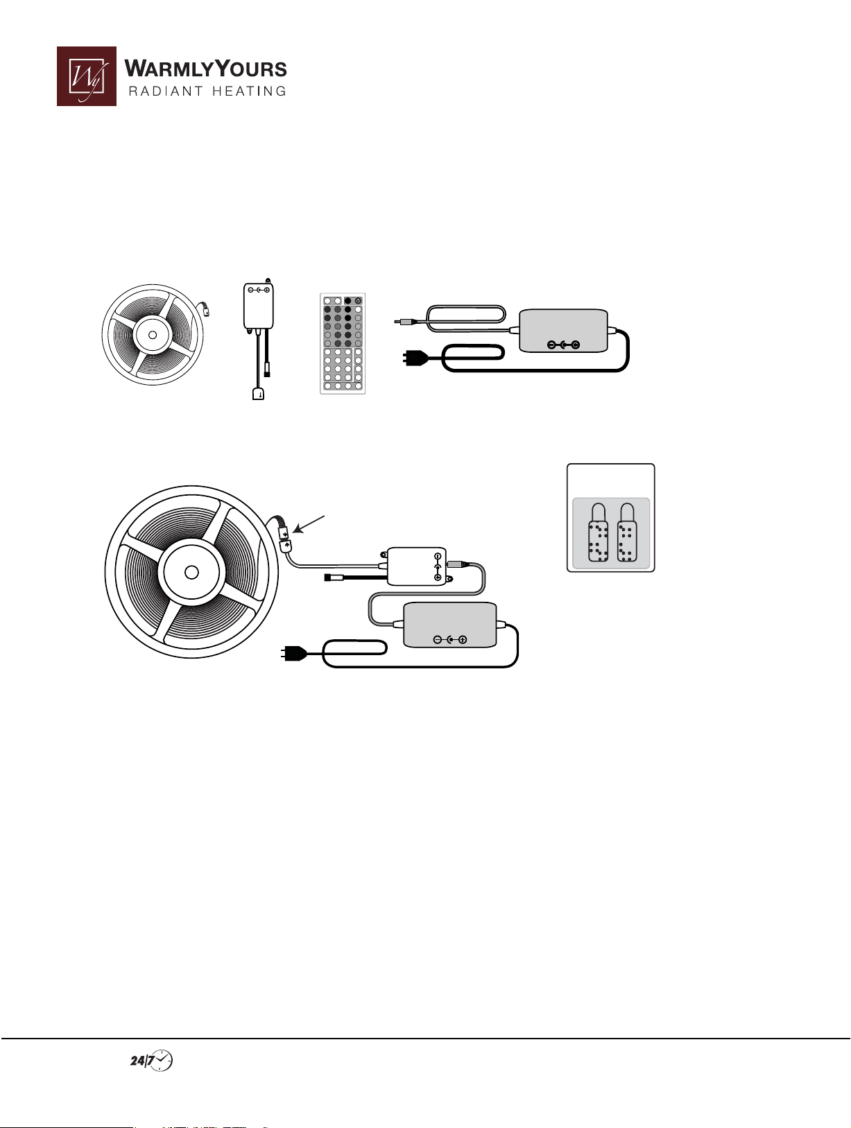
2. Identify and verify kit contents as listed below.
INPUT: DC 12V
OUTPUT: DC 12V
CONTROLLER
MODULE
LED Spool LED Controller LED Remote LED Power supply (transformer & removable line cord)
AC/DC ADAPTER
INPUT: 120VAC
OUTPUT: 12 VDC 4A
Velcro Strips
When making this connection verify
that the arrows line up.
OUTPUT: DC 12V
INPUT: DC 12V
CONTROLLER
MODULE
AC/DC ADAPTER
INPUT: 120VAC
OUTPUT: 12 VDC 4A
Velcro
Strips
3. Assemble the parts as shown. Test the system to see if it is functioning correctly. Operation instructions
come separately. If the unit does not function, please call WarmlyYours Technical Support department at
800-875-5285. If the system operates correctly, disconnect unit from power and disconnect all other connections and proceed to Step 4. Warning: Do not operate spooled LED’s for more than a couple of minutes during
testing. Spooled LED’s can overheat rapidly and damage may result.
Attach LED strip to the LAVA
4. Remove LED strip from spool.
5. Locate the “scissor” icon on the LED strip. This icon repeats at equal distances throughout the entire length of
the strip. This is where the strip can be cut to the correct length for the installation. Never cut the strip at any
other location, doing so will permanently damage the product and void the warranty. Do NOT cut the strip until
instructed!
6. Very carefully place the LAVA unit face down on a non-abrasive surface, like carpeting. All LED attachments
are done on the rear of the unit. Loosely attach mounting brackets to rear of LAVA to conrm clearances of LED’s
and electrical components.
Installation Support • No Nonsense™ Warranty •(800) 875-5285 • www.WarmlyYours.com
Page 2
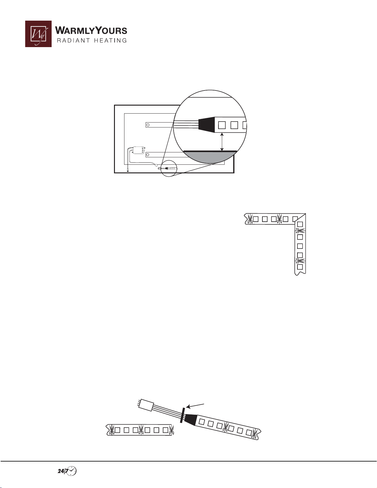
7. Place the LED Controller next to bracket as shown. This will ensure proper placement of the controller sensor
and the starting location of the LED Strip. Locate beginning of LED strip at the middle of the bottom of the LAVA
unit so that the lighted portion is located within 2” of the bottom edge.
O
INPUT: DC
C
U
O
TPUT:
M
N
O
TR
D
O
ULE
D
L
C
LER
12
12V
V
2”
8. Secure the LED strip temporarily every 3”-4”with tape as it is being laid into the lower, right corner (looking at
unit from the rear). This rst run will slightly decend from 2“ to 1” from the edge in the rst corner. This will allow
for any necessary overlap at the end of the LED Strip.
9. As the strip approaches the rst corner, bend the strip as shown to
form a 90-degree turn. Do not fold strip directly at an LED or at the area
where the “scissor” icon appears. The strip may need to be adjusted for
the best location of the fold.
10. Continue to place the LED strip within 1” along the right, outside edge, using the tape to temporarily hold it
in place.
11. Repeat the folding procedure as in the previous corner. Repeat this for the nal 2 corners.
12. After making the turn in the lower left corner, it is time for the nal measurement. As the strip comes out of
the bottom left corner, it will need to be marked for nal cutting. PLEASE TAKE NOTE: If there is too great of a
gap between the END of the strip and the beginning of the strip, the reected light in that area will not be the
same intensity as the rest of the unit. If installed in this manner, the LED brightness at the bottom of the
installed LAVA may appear dimmer than the other sides. It is better to have a little overlap in LED coverage than
it is to have a gap and the resulting lower level of brightness. The LED strip should terminate within an inch of
the bottom edge. Take note that excessive overlap of the LED sections will result in a brighter area visible in that
area. The “Beginning” of the strip will need to be located closer to the center of the unit if there is overlap, that
way the line cords will not block any light from reaching the wall. It is better to do this sizing before actually
cutting the strip and mounting it because once the LED strip has been cut, it is not returnable/refundable.
START POINT
Installation Support • No Nonsense™ Warranty •(800) 875-5285 • www.WarmlyYours.com
Page 3

13. Make a mark at the “scissor” icon that is closest to the desired “end” location but do NOT cut the LED strip at
this time. This is the tentative ending point of the strip.
14. Use a marker to note folding locations on the front of the LED strip.
15. Using a marker or piece of tape, mark the location of the LED strip “START” point on back of the LAVA.
16. Remove the tape pieces temporarily securing the LED strip to the back of the LAVA.
17. Locate the mark on the LAVA that was made to indicate the “Beginning” of the LED strip.
18. Begin to peel back the LED strip’s paper backing at the “Beginning” end of the LED strip. The backing of the
LED strip has a pressure-sensitive adhesive surface. Push the led strip rmly to the back of the lava.
START
POINT
19. Remove the paper backing to expose enough of the LED strip to make the bend in the lower right corner.
This should be visible by the mark previously made on the front of the strip indicating the rst corner fold.
BACKING
20. Repeat STEP 18 for attaching the LED strip to the right, top and left sides of the LAVA.
21. After attaching the LED strip in the lower left corner, route the strip WITHOUT removing the paper backing
along the lower edge of the LAVA to see where the nearest or pre-marked “scissor” icon comes to rest in relation
to the “beginning” of the strip. SEE STEP 11 CONCERNING LED COVERAGE AT OVERLAP.
22. Once the cut point of the LED strip has been determined and double-checked, cut the strip with scissors at
the chosen “scissor” icon.
23. Remove the paper backing from the LED strip and push the strip rmly to the rear of the LAVA unit to attach
the nal section of the strip.
24. Long-term testing has proven the ability of the LED adhesive to stay rmly attached to the rear LAVA
surface. For added peace-of-mind, a high quality tape (3M Scotch Tape, or similar) can be used in each corner of
the LAVA and at the “Beginning” and “END” of the run for extra support. See illustration.
TAPE
Installation Support • No Nonsense™ Warranty •(800) 875-5285 • www.WarmlyYours.com
Page 4

25. Place the included Velcro strip on the controller and place the controller at the back of the LAVA, ensuring
that the sensor (pictured) comes to rest within a half inch of the bottom edge of the unit. This allows the signal
to reach the controller, without the controller being visible from the front of the unit. Once the location is
chosen, pull the paper backing o of the Velcro to expose the adhesive backing. Press the Velcro rmly to the
controller and the controller rmly to the LAVA.
26. Place the included Velcro strip on the LED Power Supply Transformer and place the transformer at the back
of the LAVA. Once the location is chosen, pull the paper backing o of the Velcro to expose the adhesive backing. Press the Velcro rmly to the transformer and the transformer rmly to the LAVA.
Attach the power lead from the transformer to the controller. With the help of an assistant, lift the Lava to plug
transformer into wall socket. Attach transformer to rear of the Lava. Attach Lava unit to wall. See Installation
Instructions for further information concerning mounting Lava to the wall.
AC/DC ADAPTER
: 120VAC
CONTROLLE
MODULE
R
O
U
TPUT:
DC 12V
INPUT: DC 12V
INPUT
UTP
O
A
4
C
D
: 12 V
UT
Installation Support • No Nonsense™ Warranty •(800) 875-5285 • www.WarmlyYours.com
 Loading...