

Page 1
ET-PWR-END-KIT Installation Instructions
(part #JSR00)
Please read and save these instructions. Read carefully before attempting to assemble, install, operate or maintain the product described.
Protect yourself and others by observing all safety information. Failure to comply with instructions could result in personal injury
and/or property damage. Retain instructions for future reference.
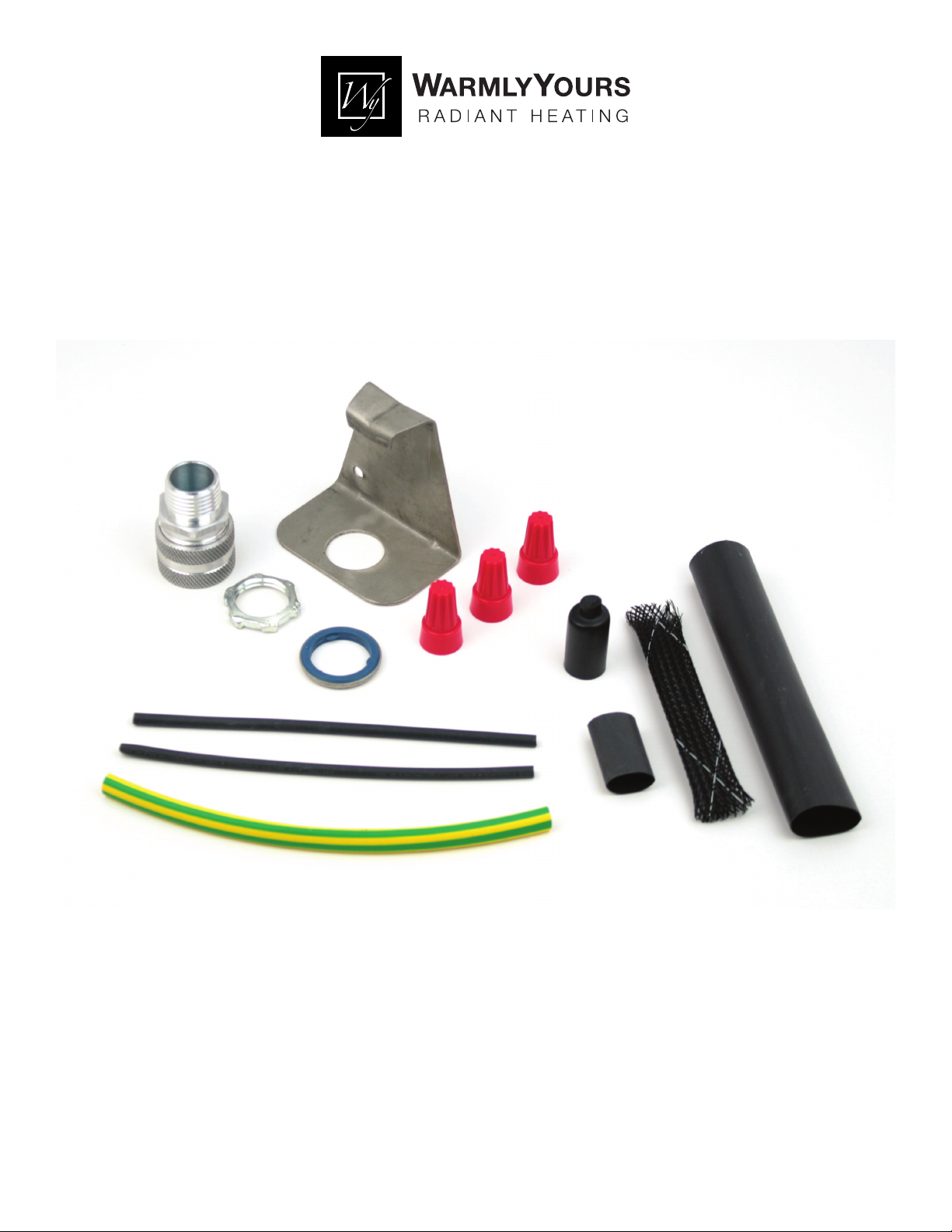
Description: The ET-PWR-END-KIT power connection kit (part #JSR00) is suitable for use only with the ET-SR series heating cables.
The kit provides material for one power connection and one termination.
The ET-SR series cables can be used for pipe freeze protection and/or roof and gutter deicing.
This manual includes installation instructions for the ET-PWR-END-KIT and the ET-END-KIT End Seal Kit (part #JSR12).
Free Design Service • 24/7 Installation Support • (800) 875-5285 • www.WarmlyYours.com
Page 2

ET-PWR-END-KIT Installation Instructions
ET-PWR-END-KIT
Assembly Tools Needed
• Utility knife
• Wire cutter
• Needle-nose pliers
• Adjustable wrench
• Pen
• Screwdriver
• Heat gun
• Measuring tape
General Safety Information
Read and understand all instructions in this manual, including all installation instructions and safety warnings, before beginning
the installation. Electrical cables can present a fi re, shock, and arcing hazard if they are damaged or not installed correctly.
1. Installation must be in compliance with the National Electrical Code (NEC).
2. Use 30-mA ground-fault protection on each heating cable branch circuit for maximum protection.
3. The black heating cable core is conductive and can short. It must be properly insulated and kept dry.
4. The conductive layer of this heating device must have a suitable grounding terminal.
5. Installer should apply the nameplate label to surface of the junction box.
6. Keep components and ends of heating cable dry before installation.
7. Do not break braid or bus wire strands when scoring the jacket or core. Damaged bus wires can overheat or short.
8. Keep the bus wires separated. The bus wires will short if they touch each other.
9. Replace damaged parts. Heat-damaged components can short.
10. Use heat gun or torch with a soft yellow, low-heat fl ame--not a blue fl ame. Keep the fl ame moving to prevent overheating or
blistering the heat-shrinkable tubes.
11. Do not heat other components.
12. Use only fi re-resistant insulation materials such as fi berglass wrap.
13. De-energize all circuits before installation or service.
14. The heating cable should not be embedded in insulation or roofi ng material.
15. Do not twist cable during installation.
16. Save all instructions for future reference.
CAUTION: Charring or burning the heat-shrinkable tubes in this kit will produce fumes that may cause eye, skin, nose, and throat
irritation.
1
Page 3
ET-PWR-END-KIT Installation Instructions
ET-PWR-END-KIT
G
J
H
C
D
F
E
FIRE AND ELECTRIC SHOCK
A
B
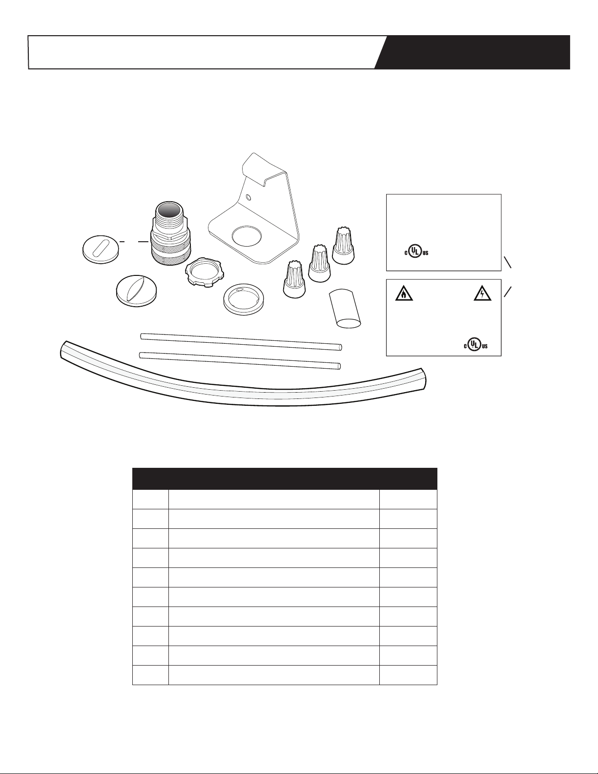
Item Description Quantity
CAUTION:
ELECTRIC DEICING AND
SNOW MELTING EQUIPMENT
ON THE PREMISES!
I
WARNING
ELECTRICALLY HEAT TRACED!
DISCONNECT BEFORE SERVICE!
A Black Shrinkable Tubing (1/8 in. × 5 ½ in. ) 2
B Green/Yellow Shrinkable Tubing (1/4 in. × 6 in. ) 1
C Seal Fitting and White Grommet 1
D Lock Nut 1
E Black Shrinkable Tubing (1/2 in. × 1 in.) 1
F Gasket 1
G Blue Grommet 1
H Wire Nuts 3
I Labels 4
J Mounting Bracket for Piping 1
2
Page 4

ET-PWR-END-KIT Installation Instructions
Power Connection Kit Installation Instructions
Structure of model ET-SR
ET-PWR-END-KIT
1. After the seal fi tting is open, put
the junction box cap, strain relief disk,
grommet, and body onto the power
connection of cable.
2. Slice completely around heating
cable outer jacket, and then down a
distance of approximately 7 inches
(178mm). Be careful not to cut braid
or inner jacket. Then, bend the heating
cable to break the jacket where sliced,
and peel off outer jacket.
4. Bend heating cable as shown in
Figure 4, so it can be pushed through
the braid opening.
5. Place braid to one side of cable.
Cut inner jacket of cable back
approximately 6 inches (152mm).
7. Peel back exposed wires from
central matrix material as shown in
Figure 7. Do not cut bus wire strands!
8. Cut off remaining center core of
matrix, leaving the bare conductors.
Do not cut bus wires!
3. Carefully push the braid back to
loosen and spread apart as shown in
Figure 3.
3
6. Shave off outer matrix material
from conductors with utility knife. See
Figure 6.
9. Slide the 5½-inch (140mm) black
shrinkable tubes in place up to
conductive core.
Page 5

ET-PWR-END-KIT Installation Instructions
Power Connection Kit Installation Instructions (continued)
ET-PWR-END-KIT
10. Carefully shrink tubing by continuously
moving the heat source back and forth
to heat evenly. Be careful not to damage
heating cable.
11. Slide the green/yellow tube over braid
and heat evenly to shrink.
12. Center the 1-inch (25mm) black
shrinkable tube over the end of heating
cable as shown in Figure 12.
14. While tube is still hot, pinch the tube
with pliers, between the wires, and hold for
10 seconds to ensure seal. See Figures 14-1
and 14-2.
15. Slide parts in place as shown in
Figure 15.
17. Use a metallic junction box to ensure a
proper grounding. Insert heating cable and
tighten.
NOTE: For ET-SR-240 heating cables, when
used in wet locations, follow instructions
provided with junction box to seal out water.
NOTE: Allow at least 6 in. of lead wire inside
an outlet box.
18. Make connections as shown in Figure 18.
Connect the power conductors to the cable
leads. Connect the incoming supply ground
to the cable braid and to the green ground
wire. The included wire nuts are not for use
with aluminum feed wires. The junction box
needs to be grounded.
13. Evenly heat the black shrinkable tube
until it shrinks and adhesive fl ows out both
ends.
16. For pipe protection, loosely attach the
metal pipe-mounting bracket to the pipe
with the metal band. Position the bracket
so that the cable and fi tting come straight
up and through the hole. Then, tighten the
band.
19. For roof and gutter applications, put
warning label on junction box as shown in
Figure 19.
4
Page 6

ET-END-KIT End Seal Kit Installation Instructions
(part #JSR12)
Free Design Service • 24/7 Installation Support • (800) 875-5285 • www.WarmlyYours.com
Page 7

ET-END-KIT Installation Instructions
C
ET-END-KIT
A
B
Item Description Quantity
A Heat-Shrink Tube (5 in. long x ¾ in. dia.) 1
B Woven Braid Sleeving (4 in. long x ½ in. dia.) 1
C Heat-Shrink Cap (½ in. dia) 1
WARNING:
ELECTRIC SHOCK HAZARD: Disconnect all power before installing or servicing heating cable and accessories. A qualifi ed
person must perform installation and service of heating cable and accessories. Heating cable must be effectively grounded in
accordance with the National Electrical Code. Failure to comply can result in personal injury or property damage.
Note:
1. All electrical wiring, including GFCI (Ground-Fault Circuit lnterrupters), must be done according to the National Electrical Code
or local codes by a qualifi ed person.
2. Article 426 of ANSI/NFPA 70 of the National Electrical Code (NEC) and Section 62 of CAN/CSA-C22.1, Canadian Electrical Code,
Part I (CEC) govern the installation of this heat system.
3. The ET-END-KIT End Seal Kit is suitable for use with ET-SR heating cables.
4. Keep ends of heating devices and kit components dry before and during installation.
ELECTRIC SHOCK HAZARD: To prevent short circuits, do not connect the bus wires together. Keep braid out of heat shrink cap.
46DV PIPE HEATING CABLE &
4FB1 DEICING AND SNOW
MELTING EQUIPMENT
1
Page 8

ET-END-KIT Installation Instructions
END SEAL KIT INSTALLATION INSTRUCTIONS
ET-END-KIT
1. Score the outer jacket 2 in. from the
end of the cable. Remove the jacket to
expose the braid.
CAUTION: When removing the outer
jacket, be careful not to damage the
braid or the base cable insulation.
2. Push the braid back and cut ¾ in. off
the end of the base cable.
7. Apply heat evenly to the heat shrink
tube until it shrinks around the cable.
4. Pull the pushed-back braid over the
sealed end cap and twist the braid end
together.
8. While the shrink tubing is still hot,
gently squeeze the end of the shrink
tube with pliers and hold until cool.
The end must remain visibly sealed
when the pliers are removed. If the
tube does not remain sealed, then
repeat steps 7 and 8.
5. Slide the 4 in. woven braid sleeving
over the end of the cable, allowing at
least ½ in. to extend past the end of
the cable.
3. Slide the heat-shrink cap over the end
of the cable. Apply heat evenly until it
shrinks around the cable.
2
6. Slide the 5-in. heat-shrink tube over
the woven braid piece, allowing ½ in.
to extend past the end of each end of
the woven sleeving.
 Loading...