

WarmlyYours Infinity User Manual
Hardwired Model Shown
Installation & Operation Manual for
WarmlyYours Innity Towel Warmers

Thank you for choosing a nely crafted WarmlyYours Innity towel warmer.
The Innity’s radiant heat gently warms your towel or bathrobe, allowing you
to wrap yourself in luxurious comfort as you step out of the bath or shower.
Included in this document are all necessary installation and operating
instructions.
To locate the model number, refer to the product label as shown in Diagram
D on page 8. If you encounter any diculties while installing your towel
warmer, installation support is available by phone between 8:00 a.m. and
5:30 p.m. CT, Monday through Friday by calling (800) 875-5285. If a return
is necessary, please use original packaging.
SAFETY INFORMATION
• Never stand, sit on, or hang on the towel warmer unit.
• Never allow children to play on or with the towel warmer.
• Make sure that the electrical circuit breaker is shut o at the main panel before
wiring or servicing your towel warmer.
• The towel warmer must be properly grounded.
• All wiring must be in accordance with the National Electrical Code (NEC)
and Canadian Electrical Code (CEC) and should be performed by a licensed
professional who is certied to do electrical wiring.
• Never place your towel warmer inside a shower, sauna, or steam room.
• Never attempt to warm more than two (2) towels on the towel warmer at a time.
Overloading the towel warmer will cause the unit to become extremely hot and
may result in a burn if touched. (See page 10 for additional information.)
• Innity towel warmers are cULus listed for use in US and Canadian markets.
• Never use an extension cord (for plug-in model).
CLEANING INFORMATION
Clean the towel warmer with a soft, non-abrasive, damp cloth while warm.
Once the towel warmer has cooled, lightly polish with a soft, dry cloth.
Do not use abrasive cleaning powders, metal polish, or chlorine based
cleaners on any part of the towel warmer.
INSTALLATION
This appliance must be installed in accordance with the instructions in the
manual and the NEC and CEC guidelines relating to electrical xtures in
bathrooms. The towel warmer must be on a GFCI-protected circuit and be
wired by a professional who is certied to do electrical wiring. If the towel
warmer does not heat upon initial installation, PLEASE VERIFY THAT THE
POWER SWITCH, LOCATED AT THE BOTTOM OF THE LEFT, VERTICAL
POST, IS IN THE ON POSITION.
1

1. Afxing the Towel Warmer to the Wall
Step 1
Draw a diagram of the preferred location of the brackets and the electrical
connection on the towel warmer box to create a template (see Step 2 for
template instructions). At least two of the four brackets must be attached
directly to a stud.
The Innity Plug-In model must be installed less than 6 feet (183cm) from
a properly grounded outlet to ensure the plug can reach. Make sure to
measure the distance from where to plug is attached to the towel warmer to
the electrical outlet. Do NOT use an extension cord to make the connection
between the towel warmer plug and outlet.
Step 2
A. Attach tubing into desired positions on the towel warmer (see pages 5-8
for bracket assembly).
B. Place towel warmer on the box (or a large sheet of paper) and lay on a
at surface with brackets facing downwards.
C. Mark the location of the following:
• The electrical collar (hardwired model only)
• The location of the brackets
D. Use the template as a guide to mark the wall with the correct locations
of the four brackets, ensuring the following:
• The electrical collar is lined up with the center of the electrical
box (hardwired model only). Plug-in model must be installed less
than 6 feet (183cm) from properly grounded outlet. Do NOT use
an extension cord.
• At least two of the brackets are lined up with a wall stud.
• The towel warmer is level.
Step 3
Install the brackets onto the wall. Use the drywall anchors that are
supplied for the brackets that are not being installed into a stud. Refer to
Diagrams A and B.
2
1. Afxing the Towel Warmer to the Wall (continued)
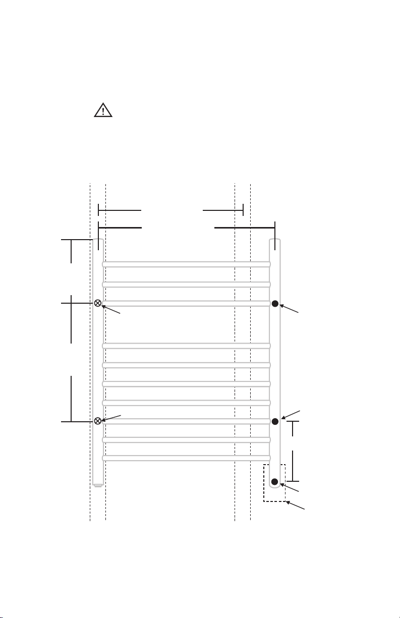
Note: Dimensions shown are distances between the center of anchor
points. This example shows 16 inches on center construction. Your
situation may vary depending on stud spacing.
WARNING: Locations of electrical box and anchor points may vary.
Measure all dimensions prior to rough-in and installation.
Diagram A: Anchor Points and Electric Box Location
stud stud
16” (406mm)
3/8
22
” (568mm)
8”
(203mm)
anchor point
15
1/4
anchor point*
”
(388mm)
anchor point*
†
Note: For hardwired model only, electrical box must be securely attached to a
stud. Plug-in model only must be installed less than 6 feet (183cm) from
properly grounded outlet. Do NOT use an extension cord.
* Note: Anchor points must be attached to a stud.
anchor point
1/8
” (206mm)
8
electrical collar
electrical box
3
†
 Loading...