

WarmlyYours AIRSS Installation Manual
Pavement-Mounted Snow and Ice Sensor
SNOW SWITCH
®
MODEL SIT–6E
For Use With any APS series
or EUR–5A Control Panel
Installation and Operation Manual
The Snow Switch® Model SIT–6E Pavement-Mounted Snow and Ice Sensor reliably detects snow and ice conditions on pavement
surfaces when used with any APS series or EUR–5A Control Panel. This ensures that deicing heaters operate only while needed which
minimizes energy costs without sacrificing snow melting effectiveness. As part of a snow melting system, an SIT–6E sensor will
signal for snow and ice melting at pavement temperatures below 38°F (3.3° C) while moisture in any form—including water, snow,
sleet or ice—is present. Operation in the 32° to 38°F (0° to 3.3°C) temperature range speeds the process, eliminating otherwise
slow melting. A built-in hold-on timer keeps heaters operating for an hour after snow stops to help ensure complete snow melting.
The SIT–6E sensor accurately measures pavement temperature by compensating for its internal heating. This eliminates the
cost and complexity of a separate pavement temperature sensor. For improved efficiency, products mount close t o the deicing
heaters to ensure that pavement and sensor become dry at about the same time.
Packing List
Item description
SIT–6E Assembly (with 60' leads)
Installation Manual (this document)
Duct Seal, 1 lb.
Screw, Set, Hex Socket, 3/8-16, 0.25" L (Qty 3)
Screw, Machine, S-BH-SS, #8-32, 0.375 L (Qty. 3)
Hex L-Key, 3/16
NOTE: The SIT–6E Sensor requires Pavement Sensor Housing with its
accompanying installation sheet .
MANUAL
Sensor
Housing
General Guidelines
1. For the greatest installation flexibility, use extra pavement sensor housing
units per paved slab. NOTE: not all pavement sensor housing units will
contain an actual sensor.
2. Prior to paving, make sure the sensor housing units are clear of the heating
coil. Do not locate a sensor housing box on top of any portion of the actual
heating coil.
3. Because there are two ports on the bottom of each sensor housing unit,
dig a little trench slightly deeper underneath each of the housing units to
accommodate those ports.
4. Read all enclosed product information sheets for additional information.
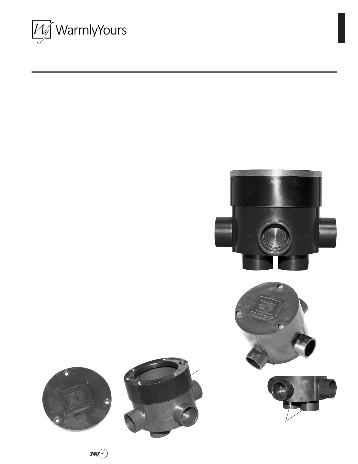
Height
Adjustment
Ring Cap
Adjustment
Pavement Sensor
Housing Unit
Height
Ring
Pavement Sensor
Housing Unit: Height
Adjustment Ring cap
removed for sensor
mounting
Two ports at bottom
of Pavement Sensor
Housing Unit
Installation Support • (800) 875-5285 • www.WarmlyYours.com
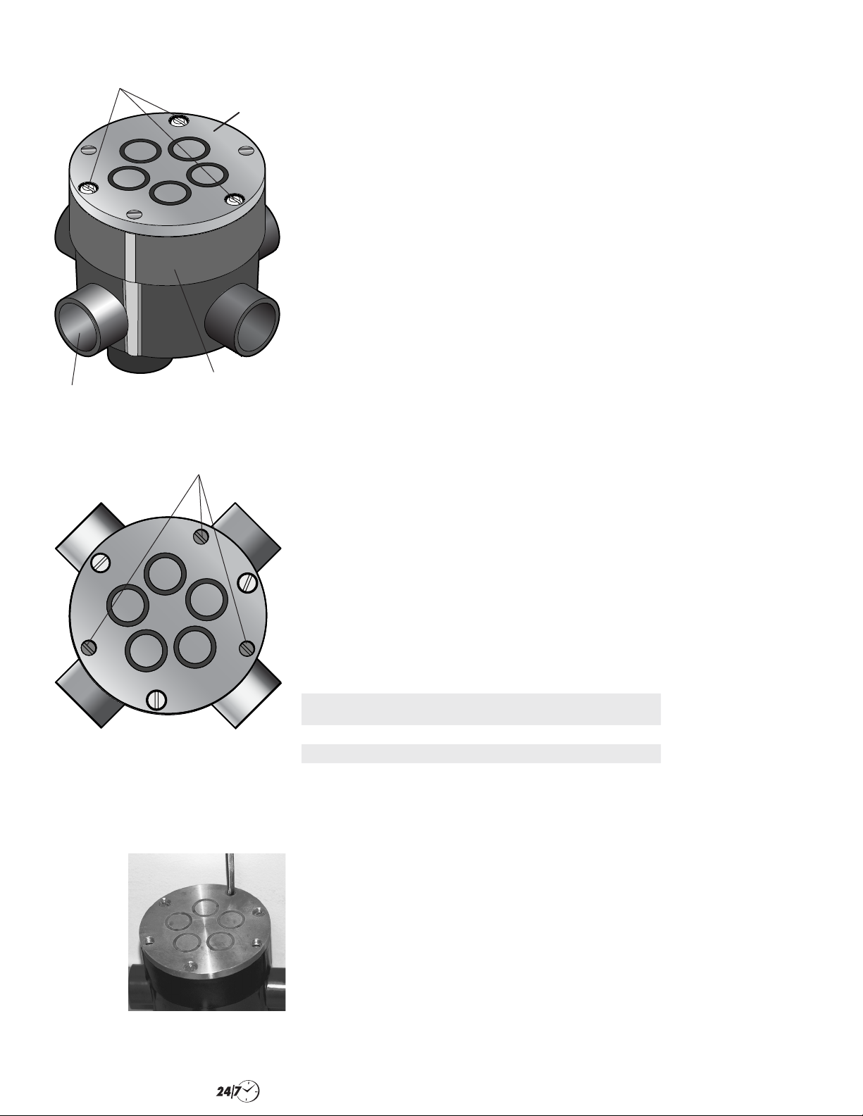
Snow Switch Model SIT–6E
Sensor Retaining
Screws (3)
Knockout Port
(6 locations)
Height Adjustment Screws (3 Places)
(shown with protective Allen-head set
Height
Adjustment
Ring
screws removed)
Sensor
Installation Instructions
1. Lay out the sensor housing units or floor boxes according to your plan for the size and
shape of the pavement area and traffic overflow area.
2. Using a screwdriver or similar tool, remove the desired knock-out seal(s) from the floor
boxes. (Not all are used.) Knock out one of the two bottom seals in each floor box as
well for greater stability as described in step 6 below.
3. With the cap off, rotate each of the three height adjustment screws to the left to raise
the height adjustment ring between 1/8 and 1/4 of an inch. Refer to Figure 1.
4. Once the adjustment ring has been raised, apply a layer of grease to the outside of
the sensor housing body underneath the height adjustment ring. Also apply grease to
the adjustment ring itself. Applying plenty of grease ensures the continued and proper
operation of the height adjustment ring after the pavement sets up and cures.
5. Rotate each of the three height adjustment screws to the right to lower the height
adjustment ring to lowest setting. Put caps back on housing units using the three
retaining screws from the accessory kit.
6. Run PVC conduit between the floor box ports opened in step 2, as well as one for the
control box wiring. Use PVC glue to secure the PVC conduit in place inside each housing
unit port. If not being used for wiring – and unless prohibited by a high water table – ETI
recommends using one of the two bottom ports as a drain with a short piece of
conduit extending down past the concrete into sand or gravel to promote draining
and to provide greater stability for each floor box.
7. As the paving material is poured and sets up, make sure the caps of all of the housing
units are flush with the pavement. There must be no paving material on the caps
of the housing units. Adjust the height flush with the pavement by using the height
adjustment ring.
8. To install a sensor into a housing unit, first select the sensor housing unit to be fitted
with the sensor. If more than one housing unit has been placed as part of the installation,
it is best to select the one it is believed will be closest to the center of the traffic or
snow build-up pattern(s).
9. Remove the sensor housing cap from the housing unit by removing the three screws
securing it in place. Make sure to retain the cap someplace at the facility in case the
location of the sensor needs to be changed in the future and the current housing has
to be closed and covered up again.
10. Connect the wires from the power cable inside the conduit to the sensor. Once the
sensor is wired, apply duct sealant to protect the installation inside the housing, leaving
room for the sensor to be placed down inside the housing. Refer to wiring table below
for connections.
Figure 1.
Sensor Housing Adjustment Points
Rotate Height
Adjustment
Screws
to the left to
raise the ring
or to the right
to lower it
Figure 2.
Rotate Height Adjustment Screws
Table 1. CABLING CONNECTIONS
CABLE LEAD
DESIGNATION
Sensor 24V Red Red
Sensor Ground Black Black
Sensor Signal White Blue
11. Once the wires are connected, place the sensor down into the housing with the sensor
top resting on the top of the housing. Verify that the top of the sensor is flush with the
pavement around it. The top of the sensor has three protective set screws, under which
are located three access holes to reach the height adjustment screws. As needed, rotate
the three adjustment screws (Figure 2) to the left to raise the height adjusting ring or to
the right to lower the ring, and then replace the three Allen-head protective set screws
(Figure 3). Install retaining screws into the sensor to secure it to the housing.
WIRE COLOR
WAS
NOTE: Any designation to sensor white lead applies now to the sensor blue lead.
CURRENT WIRE
COLOR IS
Conduit
Use individual 3/4" (20 mm) rigid conduit for the entire installed length of the sensor
cable, taking care to ensure that all embedded or outdoor couplings and terminations
are made watertight. Do not share conduit with other wiring. Do not route conduit across
pavement expansion or control joints. For sensors embedded in slab on grade, conduit
should be depressed under these joints, as necessary.
Installation Support • (800) 875-5285 • www.WarmlyYours.com
 Loading...