

Warmington Traditional Fire - Gas 1000, Traditional Fire - Gas 1200, Traditional Fire - Gas 1500 Installation Instructions Manual
23 November 2016
Due to continued product improvement, Warmington Ind LTD reserves the right to change product specifications without prior notification.
All Dimension are in mm………….Copyright ©
1
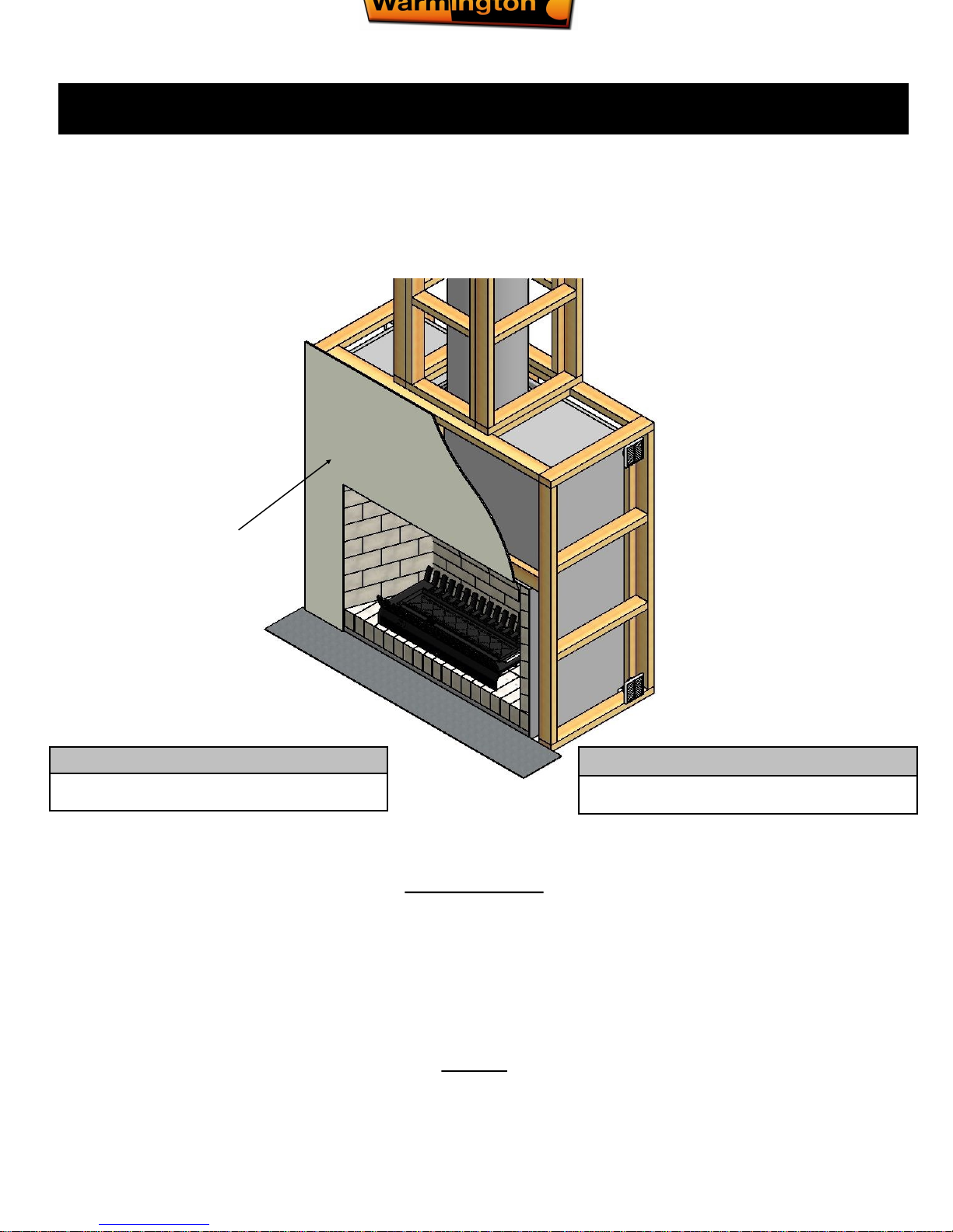
Traditional brick built open Gas fire & Gas burner
Installation Instructions
Traditional Fire - Gas 1000-1200-1500
Not included:
Bricks and Bricklaying
Hearth and Plinth
Installation
NOTE ON TRAD FIRES
Like the traditional brick built fire
of yesteryear, the Warmington
Traditional fire is built with the
experience and techniques of
the past. These make a grand
statement in the home, however
they can lack in efficiency.
Note: FLUE SYSTEMS casing...
Flue system may require to be doubled lined to comply.
Refer to relevant standard.
Note: BRICK OUT GUIDE details...
The bricking guide will come with the bricks, once
purchased.
NOTE : Non-combustible
cladding eg:
10mm Promina Board,
10mm Supalux, Latex Plaster.
(not supplied)
The fireplace is constructed and tested to comply with NZS 4558(int):2013 ‘Decorative gas log and other fuel effect appliances’.
Keep these instructions for further reference. Ensure that you have the correct and current installation details for the Warmington fireplace.
Installation
The Warmington unit is to be installed by a certified Warmington installer or an approved NZHHA installation technician.
see www.homeheat.co.nz/members for a certified NZHHA SFAIT Installer in your area.
A licenced certified gas fitter and licenced electrician are required to run power and gas supplies as required to the unit and any commissioning as part of the
installation process.The heater must be installed according to these instructions and in compliance with all relevant building, gas fitting, electrical and other
statutory regulations.
Related documents
Fire and flue system installation, and instructions to comply with NZS 5601.1:2013, 3645.1
(Int):2010, 3645.2(Int):2010, 5266:2014, 2918:2001.
23 November 2016
Due to continued product improvement, Warmington Ind LTD reserves the right to change product specifications without prior notification.
All Dimension are in mm………….Copyright ©
2
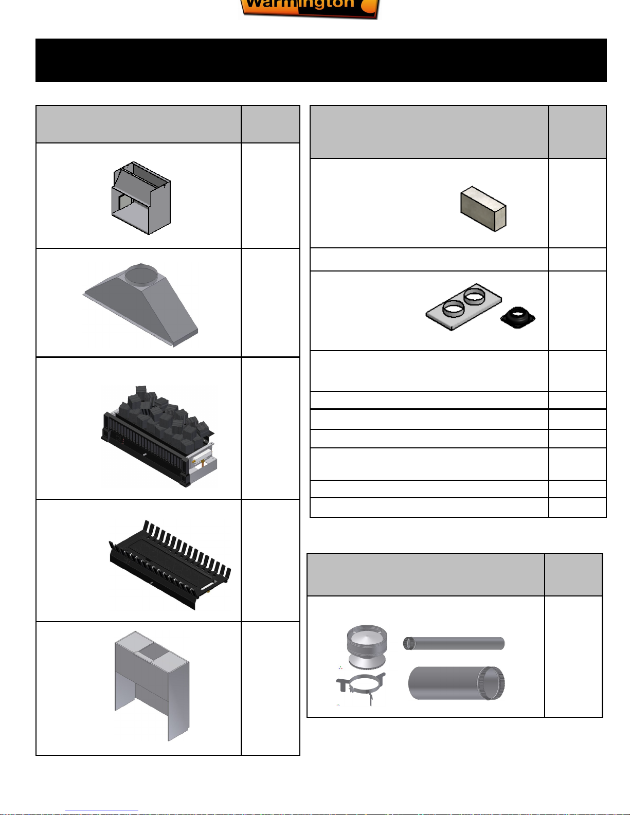
SUPPLIED
Priced depending on requirements
No:
Warmington Fluekit 1
NOT supplied
Components are required for Install
Priced depending on requirements
No:
Fire Bricks (H40) 75X115X230mm
Other Sizes Available
Varied
Fire Brick Refractite Mortar 1
Flashing System
1
Non Combustible Cladding
(Promat-Superlux-Brick-Stone etc)
10:1 Fill /Crush (vermiculite etc) . 1
Aluminium Tape, 3M Scotch Brand 1
Gas & Electrical Work Onsite 1
Installation:
Fire / Flue kit / Flashing
Installation, Brickwork
Council Permit
Components required for Construction
(supplied separately)
Supplied as Trad. SG-EG Fire
Box
No:
Traditional Firebox 1
Traditional Firebox Adaptor 1
Gas Burner
(Option 1)
1
Custom Gas Grate Burner
(Option 2)
1
Heat Shield 1

23 November 2016
Due to continued product improvement, Warmington Ind LTD reserves the right to change product specifications without prior notification.
All Dimension are in mm………….Copyright ©
3
POINTS TO CONSIDER PRIOR TO INSTALLATION
Prior to Construction and Installation Important Notes:
Consult a licenced certified gas fitter for correct gas installation.
Install to current standards.
Install to manufacture’s specifications.
All new installations require a permit.
For special requirements concerning materials (timber mantle and surrounds) within close proximity of Warmington products, please contact
your local Warmington Technical Consultant or designated Installer.
Stage 1: Frame Construction Procedure by Builder.
Mark out Flue Centre on Floor.
Mark out Heat Cell Clearance requirements.
Construct Plinth only, to required height. *
Stage 2: Install Procedure by Certified “Warmington Installer” or ‘NZ Home Heating Association Installer’ only. (See www.homeheat.co.nz)
Fit Fire to Plinth.
Fit Adaptor to Firebox.
Construct Hebel Enclosure around the Traditional Firebox.
Fit Flue System.
Fit Cowl and Flashing System
Stage 3: Finishing Procedure by Builder. NOTE : Bricklaying of Firebricks can be carried out by clients Bricklayer at a Convenient time.
Construct Hearth to required thickness. *
Finish Hebel enclosure and Hearth to Customers requirements (e.g. paint / tiles ).
Close in Hebel enclose and chimney chase . ( If in timber Alcove ).
* Note: A Certified Installer can Install Hearth and Plinth also.
Ensure that the Warmington and flue system is swept annually or more frequently if required.
INSTALLATION ORDER OF OPERATIONS Installation is not provided
Location of the Fire. Open fires are better located at one end of a room or area, as they project the heat away from their op ening.
The Topography of the land .
The slope and position of the land in relation to the home has a bearing on how the wind will interact with the fire an d flue system. Care needs to be taken to ensure
that the flue termination is in the correct position to maximise performance.
The Prevailing Wind.
Care needs to be taken to ensure that the flue termination is in the correct position as wind and gusts that hits the flue and cowl system may overcome the cowl and
draft back down the flue into the home. This can be a combination of down draft and high pressure.
Hearth and Plinth:
The Height of the Hearth off the Floor. The Finishing that is to be used on the Hearth is to be allowed for at the desi gn stage.
Note : Ensure Air Intake at Base of Firebox is not blocked or restricted .
Positioning of the Flue System:
There is a maximum distance that an offset flue can be Installed . Reference to relevant standards.
Flue And Fire Clearance:
To be maintained to the Manufactures Instructions &/or Comply with appropriate Standards & Building Codes .
Pressure Differential, Venting & External Air into the Building :
All fires need air to burn and draw correctly, Kitchen Fans, Air Conditioning units, High Wind Zones, Naturally forming Draft spaces, can all have an effect on the
pressure difference from inside the building to the outside. A lower pressure in the building may induce a draft down the flue system and back into the building causing the fire to smoke or spill into the building. Care needs to be taken at the design and installation stage to adequately vent the building, or some mechanical system
to ensure that there is always a neutral or positive pressure at the fireplace and a negative pressure at the flue outlet. Thi s w ill ensur e t hat the draf t i n th e
flue system is always to the outside.
“CAITEC AIR” th e lim it s and req uir emen ts. See d etai ls i n t hese Sp ec’s
23 November 2016
Due to continued product improvement, Warmington Ind LTD reserves the right to change product specifications without prior notification.
All Dimension are in mm………….Copyright ©
4
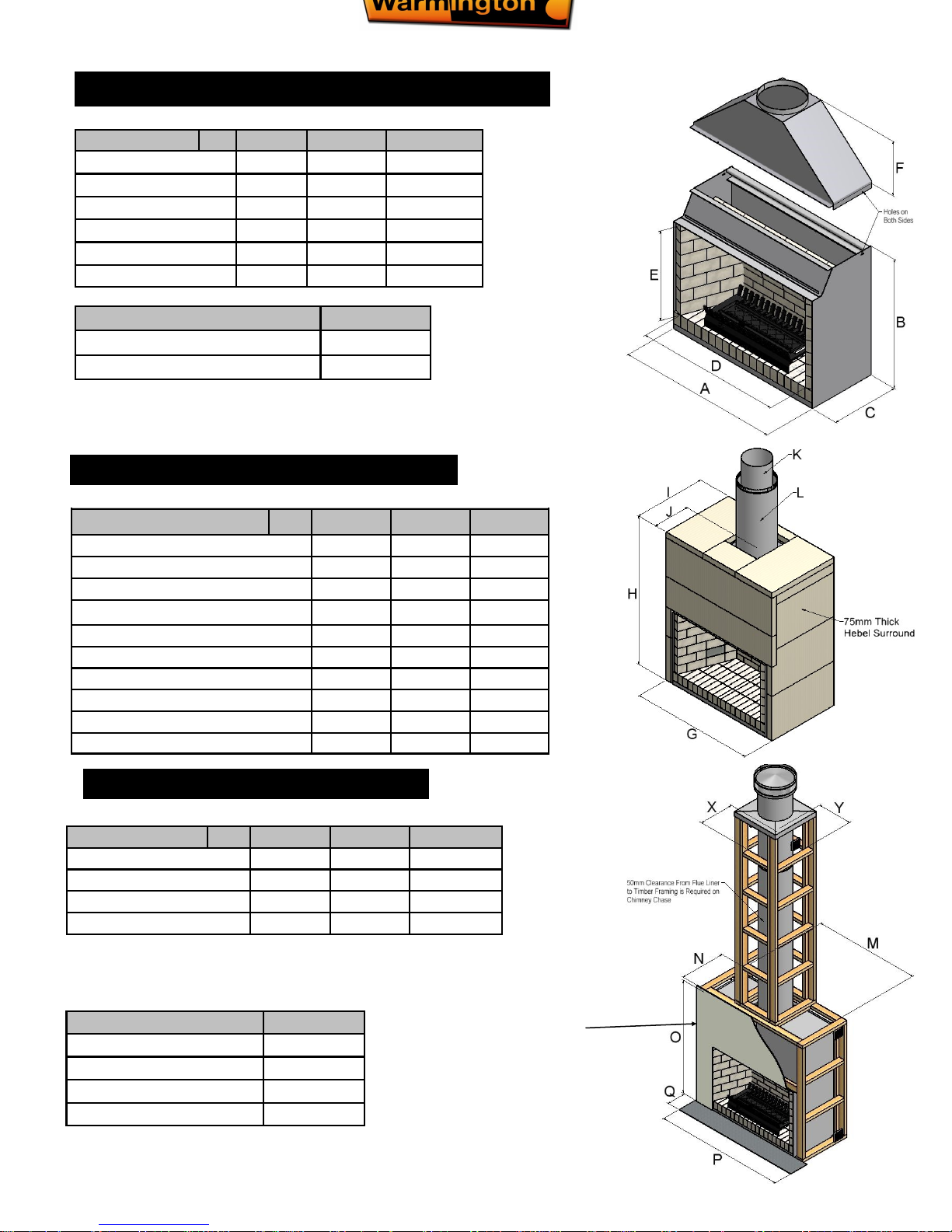
Description
TF 1000 TF 1200
TF 1500
Firebox Width
A
1240 1440 1540
Firebox Height
B
1315 1415 1238
Firebox Depth
C
735 835 650
Flange Width
D
1000 1200 1389
Flange Height
E
700 800 860
Adaptor Height
F
405 480 523
WARMINGTON TRADITIONAL FIREBOX DIMENSIONS
HEAT SHIELD DETAILS DIMENSIONS
Description
TF 1000 TF 1200 TF 1500
Heat Cell Width
G
1440 1640 1740
Heat Cell Height
H
1820 1995 1860
Heat Cell Depth
I
865 965 780
To Centre of Flue
J
538 589 441
Flue Diameter
K
300 350 400
Liner Diameter
L
350 400 450
Heat Cell Clearance Width
M
1490 1690 1790
Heat Cell Clearance Depth
N
890 990 805
Heat Cell Clearance Height
O
2150 2150 2015
Chimney Chase Clearance
X
450 500 550
Minimum Flue Height
Flue Height 3600
Measured from top of adaptor B + F + 3600
Check List
Firebox
Grate
Adaptor & Bolts
Packed by
Description
TF 1000 TF 1200 TF 1500
Hearth Width
P
1550 1800 2040
Hearth Projection
Q
300 300 300
Plinth Width
R
1440 1640 1740
Plinth Depth
S
865 965 780
TIMBER FRAMING
NOTE: Non-combustible
cladding eg:
10mm Promina Board,
10mm Supalux,
Latex Plaster.
(not supplied)

23 November 2016
Due to continued product improvement, Warmington Ind LTD reserves the right to change product specifications without prior notification.
All Dimension are in mm………….Copyright ©
5
IMPORTANT NOTES:
*Note: If Solid Plastering the Heat Cell structure, it is recommended to use a Fibreglass Mesh with a Latex Based Plaster to
minimise the chance of the Plaster cracking. (See your Solid Plasterer for correct materials and applications).
* Inlet Pressure not to exceed 4.0kPa
GAS SPECIFICATIONS Tested to current gas standards
NOTE : All Test Pressures are tested by a Independent Test Lab
MODEL
TF 1000 TF 1200 TF 1500
LPG
Nominal Pressure kPa
2.75 kPa 2.75 kPa 2.75 kPa
Nominal Injector Size mm
2 X 1.1mm 2 X 1.2mm 2 X 1.4mm
Burner Pressure High kPa
2.5 2.5 2.5
Burner Pressure Low kPa
0.75 0.75 0.75
MJ/h
29 38 50
Flame Effect Output Only
Effect Effect Effect
Supply Pipe Size dia—min
3/8” 3/8” 1/2”
Natural Gas
Nominal Pressure kPa
1.5 kPa 1.5 kPa 1.5 kPa
Nominal Injector Size mm
2 X 1.8mm 2 X 2mm 2 X 2.4mm
Burner Pressure High kPa
1 1 1.0
Burner Pressure Low kPa
0.3 0.3 0.3
MJ/h
35 45 58
Flame Effect Output Only
Effect Effect Effect
Supply Pipe Size dia—min
3/8” 1/2” 1/2”
Lab. Test No
GL 923 GL 900 GL 876
Lab. Test Dates
20/04/2010 26/02/10 24/12/09
ESS Declaration No: 1149420106 1149520106 1149820106
HEARTH & PLINTH CONSTRUCTION DETAILS
Note: Hearth and Plinth Construction.
Plinth to be offset above Hearth by the Hearth finishing (e.g. tiles/
granite/solid plaster/etc.)
Raised hearths & plinths with canter levered hearths must be
adequately supported to take the weight in accordance with the
NZ building code.
Offset for
Hearth
finishing
Offset
This is a raised & cantilevered hearth.
See page 13 for further raised hearth
details.
Hearth & Plinth material must
be built from non– combustible material
eg. 9.5mm Promina,
Superlux, Etapan.
23 November 2016
Due to continued product improvement, Warmington Ind LTD reserves the right to change product specifications without prior notification.
All Dimension are in mm………….Copyright ©
6
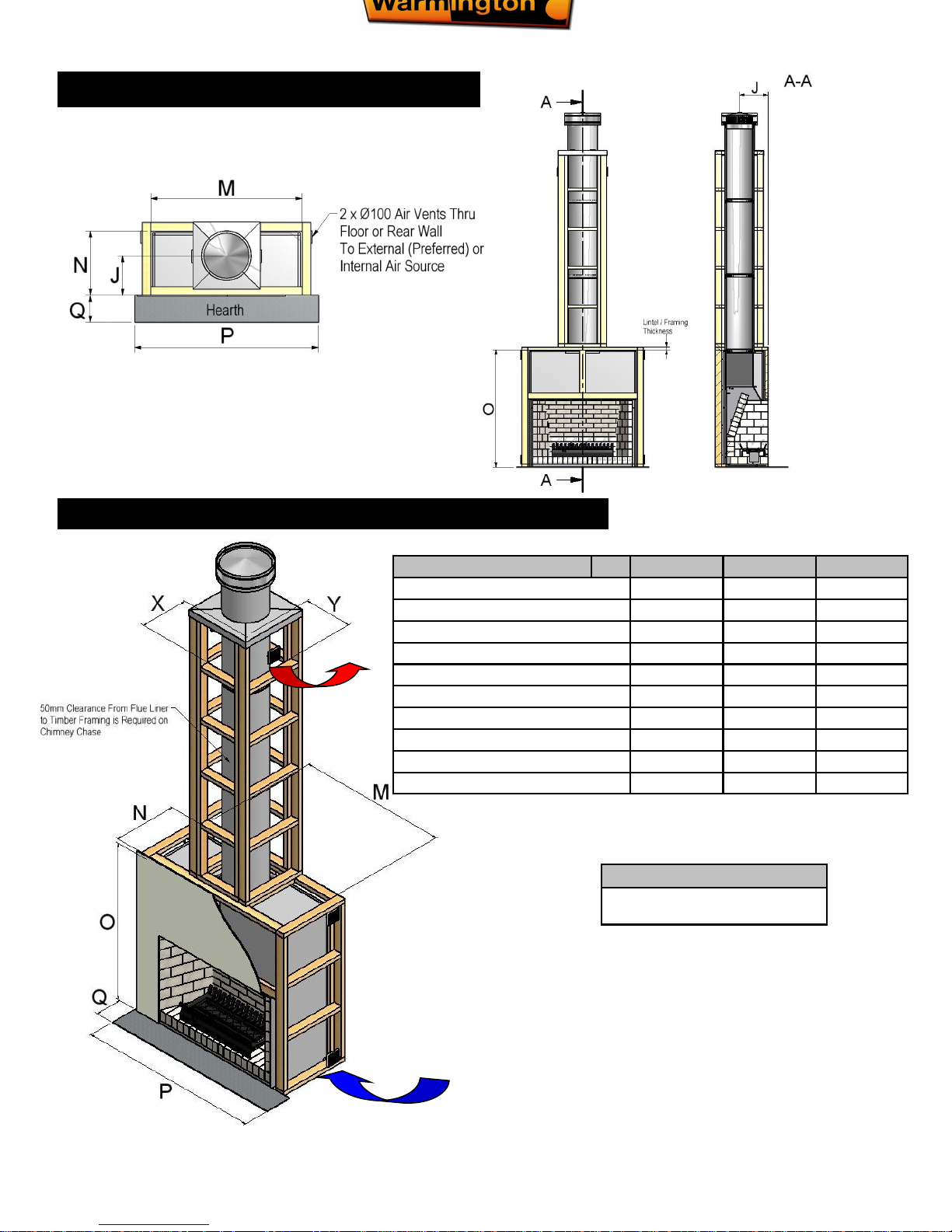
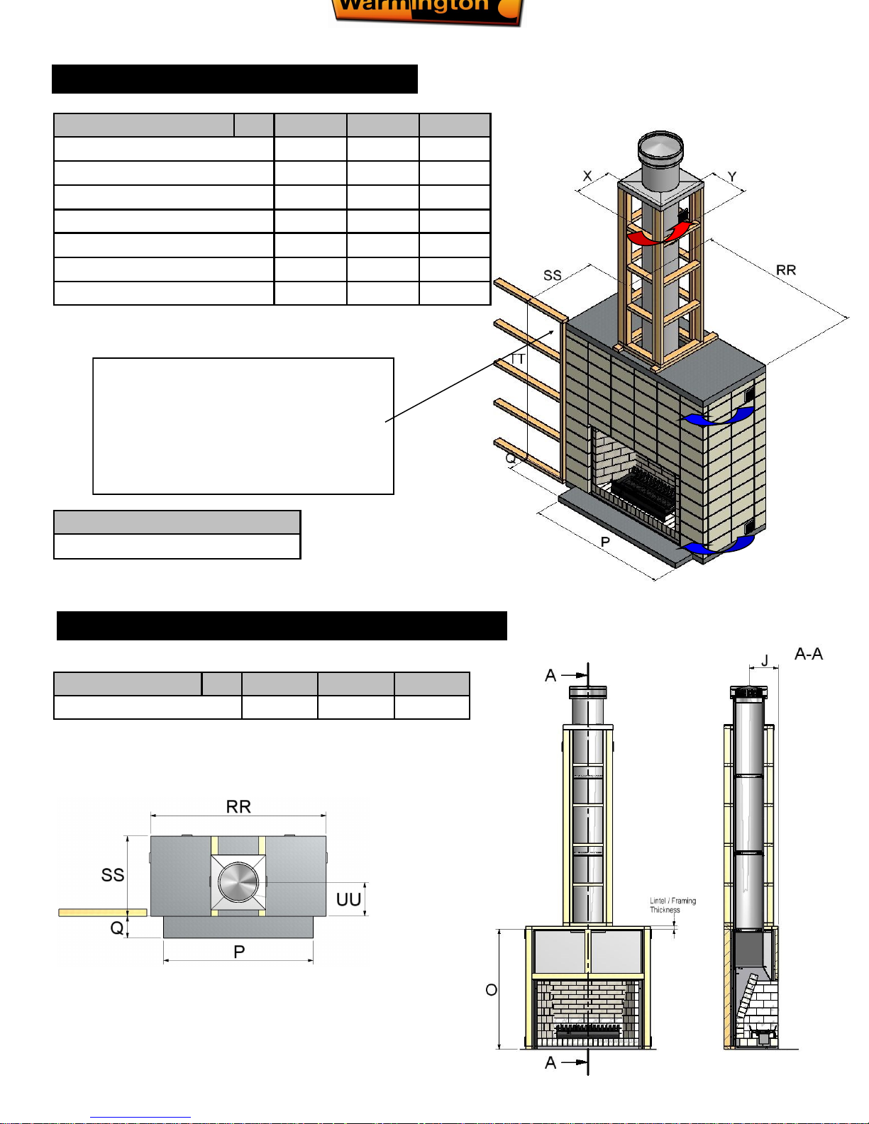
PLAN, FRONT ELEVATION & CROSS SECTION
TIMBER FRAMING & TRIM OUT DETAILS-Heat Cell Clearance
Note:
Centre line of flue is `NOT’ in centre of
alcove.
External air supply for ‘Caitec Air’ and cooling air
NOTE : Non-Combustible
cladding eg :
10mm Promina Board,
10mm Supalux,
Latex Plaster.
(not supplied)
Warm Air
Vent
NOTE : 50mm
Clearance from the
Flue Liner to Timber
Description
TF 1500 TF 1200 TF 1000
To Centre of Flue
J
441 589 538
Flue Diameter
K
400 350 300
Liner Diameter
L
450 400 350
Heat Cell Clearance Width
M
1790 1690 1490
Heat Cell Clearance Depth
N
805 990 890
Heat Cell Clearance Height
O
2015 2150 2150
Hearth Width
P
2040 1800 1550
Hearth Depth
Q
300 750 600
Chimney Chase Clearance
X
550 500 450
Chimney Chase Clearance
Y
550 500 450
23 November 2016
Due to continued product improvement, Warmington Ind LTD reserves the right to change product specifications without prior notification.
All Dimension are in mm………….Copyright ©
7
BLOCK ENCLOSURE (NO HEBEL)
BLOCK ENCLOSURE (NO HEBEL) CROSS SECTION
Description
TF 1500 TF 1200 TF 1000
Hearth Width
P
2040 1800 1550
Hearth Projection
Q
300 750 600
Solid Poured Top Width
RR
2390 2010 1610
Solid Poured Top Depth
SS
1090 1200 1000
Block Enclosure Height
TT
2390 2390 2390
Chimney Chase Clearance
X
550 500 450
Chimney Chase Clearance
Y
550 500 450
NOTE: WITHOUT HEBEL CELL
Timber Framing & Any Combustibles
To be Spaced 50mm Away From
Block work - All Around Until 2400mm
Height
Note:
Centre line of flue is `NOT’ in centre of alcove.
Description
TF 1500 TF 1200 TF 1000
To Centre Of Flue
UU
461 689 638
23 November 2016
Due to continued product improvement, Warmington Ind LTD reserves the right to change product specifications without prior notification.
All Dimension are in mm………….Copyright ©
8
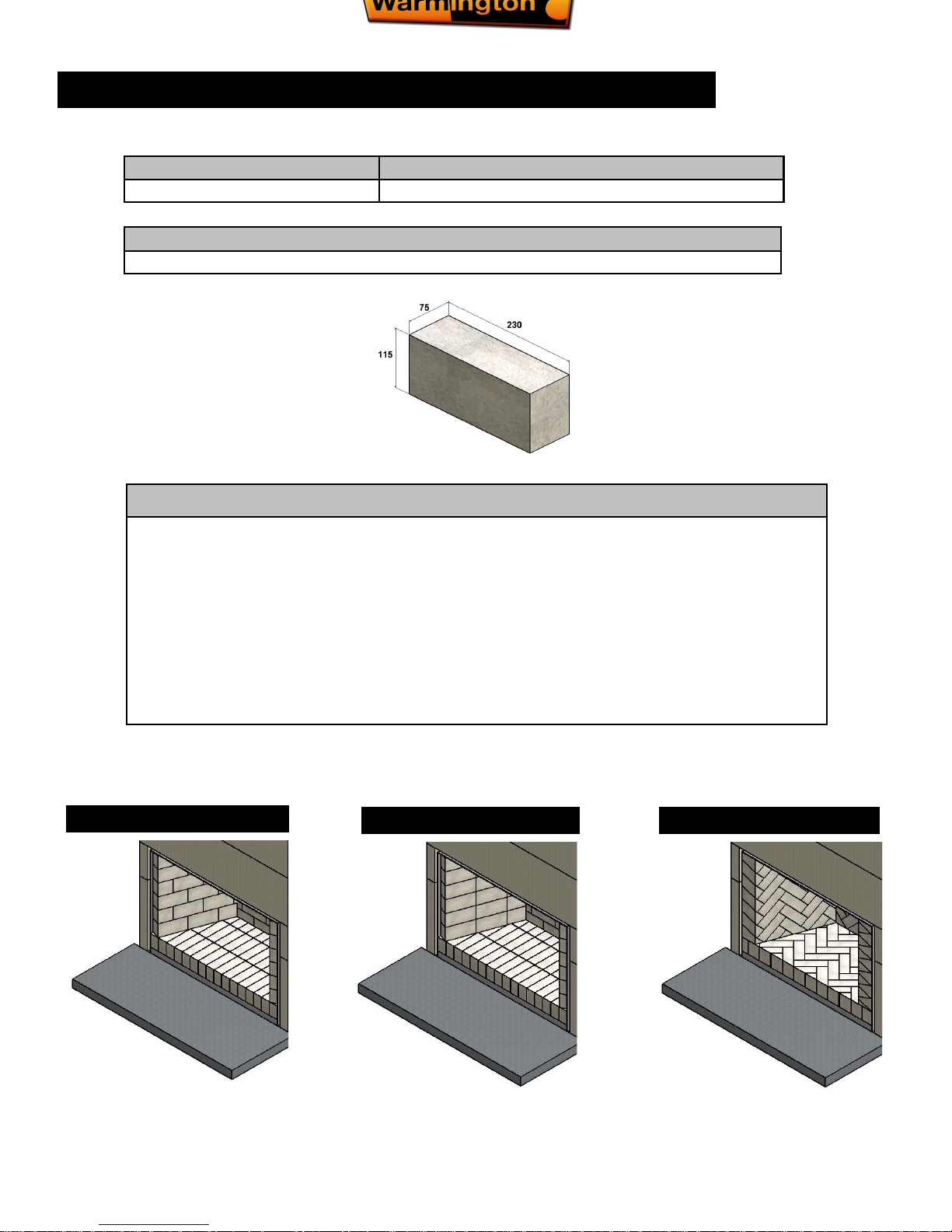
Note: BRICK OUT GUIDE details.
When purchasing the fire bricks the bricking guide will come with the purchase of the bricks only.
Fire Brick amounts
TF 1500
ORDER AMOUNT inc 12% extra Supplied with the Purchase of the Fire Bricks Only
REFRACTORY / FIRE BRICK AMOUNTS - standard
Brick size and refractite:
The standard brick out is the stretcher bond style, but other styles can be bricked
according to your liking.
Some Bricklayers prefer to us there own refractite. Please check with the Bricklayer.
Bricks come in a standard size of 230 x 115 x 75mm.
20mm and 40mm thick bricks are available and there is a increase in the cost of
these bricks and the amount that is required for the brick out.
Below shows some brick patterns that are bricked with the Standard brick size of 230
x 115 x 75mm.
Stretcher Bond Pattern
Stack Bond Pattern Herring Bone Pattern
23 November 2016
Due to continued product improvement, Warmington Ind LTD reserves the right to change product specifications without prior notification.
All Dimension are in mm………….Copyright ©
9
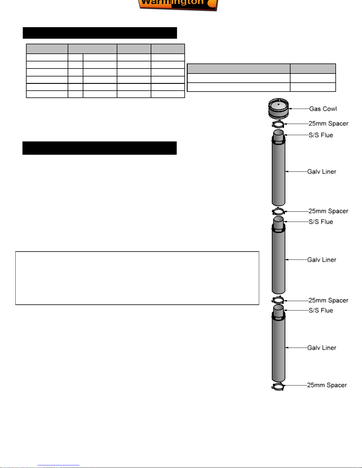
FLUE DETAILS DIMENSIONS
Minimum Flue Height
Flue height 3600
Measured from top of adaptor B + 3600
FLUE SYSTEM INSTALLATION GUIDE
This is a general installation guide only – Contact a “NZHHA Installer” or Gas Fitter for
Installation Advice.
1. Install the first length of flue pipe with the crimped end down, inside the Adaptor collar, ensure that the flue
pipe is sealed into the collar with exhaust sealant. Rivet the flue in 3 places around the Adaptor collar. Place a
bottom spacer around the flue pipe approximately 150mm above the adaptor collar. Secure in position by
tightening the screw and nut.
2. Install the second length of flue pipe with the crimped end down and fit by riveting in at least 3 places around
the flue pipe joint. Ensure that the flue is sealed into position with sealant.
3. Install the first section of flue pipe liner with the Crimped end up, over the flue pipe and over the spacer that is
fixed to the flue pipe. This spacer will keep the liner concentric about the flue pipe.
4. Position flue spacer at the flue pipe joint for every length of “Flue pipe” and “Liner”.
Repeat the Steps from 1 – 4 to the installed required height of the flue system. The flue system is to comply
with the current standards.
IF FLASHING CONE NEEDED:
1. NOTE: The las t length o f flue pipe needs t o extend past th e liner so th at when the ‘top spid er’ an d
the ‘flashing cone’ are fitted, that the ‘flashing cone’ and the ‘flue pipe’ are flush, or that the ‘flue pipe’ is
5mm lower that the ‘ fl ashing con e’.
2. Fit the ‘Top Spider’ into position, ensure that the legs of the spider are fitted inside the liner and that the
spider is positioned hard down onto the liner and tighten with the screw and nut.
3. Place the ‘flashing cone’ over the ‘flue pipe’ and press hard down onto the ‘Top Spider’. (Note that the
‘flue pipe’ and the ‘flashing cone’ are either flush or the ‘flue pipe’ is 5mm lower than the ‘flashing cone’).
Ensure that the ‘flashing cone’ is clear for the venting from the ‘Liner’ and the ‘flue pipe’.
4. Fit the ‘cowl’ to the top of the flue pipe. The ‘cowl’, ‘flashing cone’, and the ‘flue pipe’ can be secured to
each other with the uses of a stainless steel self tapping screw. This will allow the ‘cowl’ to be removed for
cleaning.
5. Flue system may require bird proofing due to the installation and locations, discuss this with your installer
for the best advice.
6. If the Flue system is installed into a ‘chimney chase’, allow for air vent as close to the top of the chase as
practical, or allow venting through the ‘chimney chase flashing’. A ‘venting flashing cone’ and a 25mm gap
around the liner with a ‘venting flashing cone-spider’ can be used.
a “the flue pipe shall extend not less than 4.6m above the top of the floor protector.”
b “ the minimum height of the flue system within 3 m distance from the highest point of the roof shall be 600mm
above that point.”
c “the minimum height of the flue system further than 3 m from the highest point of the roof shall be 1000mm
above the roof penetration.”
d “no part of any building lies in or above a circular area described by a horizontal radius of 3 m about the flue
system exit.”
Flue details
No:
TF 1500 TF 1200 TF 1000
Cowl 1 400 350 300
Top Spider 1 400 350 300
Cone
1
400 350 300
Flue Diameter 3 400 350 300
Liner Diameter 3 450 400 350
Spacer 3 300/350 350/400 400/450
NOTE:
Ensure that a standard tested Warmington Flue System is used on Warmington Fires.
 Loading...