

Warmington Studio Oven Installation Instructions Manual
21 February 2017
All Dimension are in mm………….Copyright ©
1
Due to continued product improvement, Warmington Ind LTD reserves the right to change product specifications without prior no tification.
Studio Oven—Clean Air 2016
Visit www.warmington.co.nz for Spec’s, DWG’s and PDF uploads of Fires
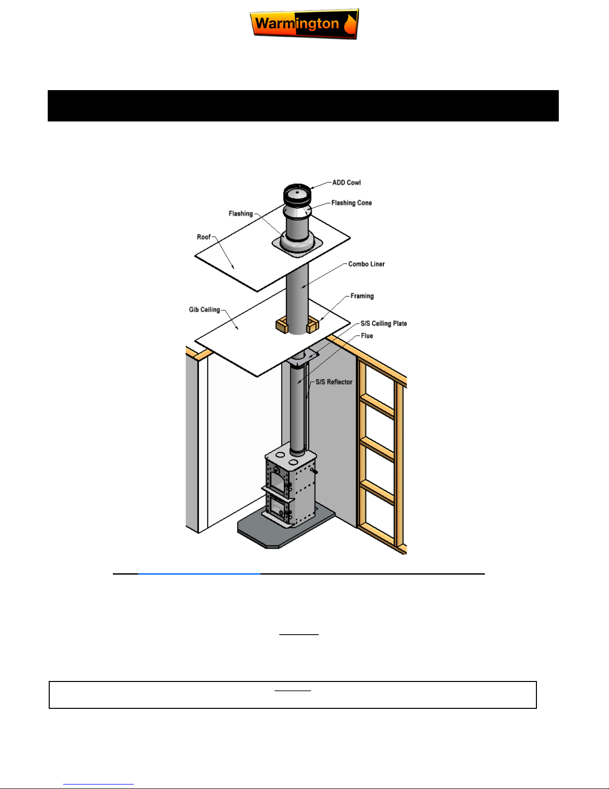
Fire, Flue System and Instructions to Comply with ASNZS 2918:2001
Keep these Instructions for further reference……Ensure that you have the correct and current Installation details for the Warmington Fire
Installation
The Warmington unit is to be Installed by a Certified Warmington Installer or an Approved NZHHA Installation Technician .
See www.homeheat.co.nz/members for a Certified NZHHA SFAIT Installer in your area .
CLEARANCES TO COMBUSTIBLE SURFACES UNLESS STATED
IMPORTANT
Read all the Instructions carefully before commencing the Installation. Failure to follow these Instructions may result in a Fire Hazard and void the warranty
Studio Oven - Wood Burner
Installation Instructions
Due to continued product improvement, Warmington Ind LTD reserves the right to change product specifications without prior no tification.
21 February 2017
All Dimension are in mm………….Copyright ©
2
Due to continued product improvement, Warmington Ind LTD reserves the right to change product specifications without prior no tification.
Model: Studio Oven
Serial No: SO - ……………………
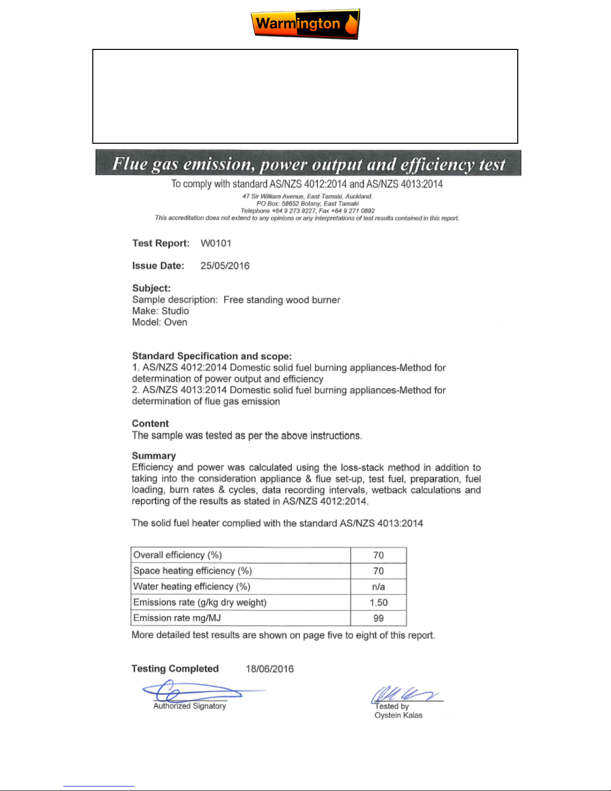
TESTED TO AS/NZS : 2918
TEST REPORT : JOHN YOLLAND & ASSOCIATES LTD
TEST REPORT NO : 98/17
Date of installation: _____/_____/20_____
21 February 2017
All Dimension are in mm………….Copyright ©
3
Due to continued product improvement, Warmington Ind LTD reserves the right to change product specifications without prior no tification.
Description
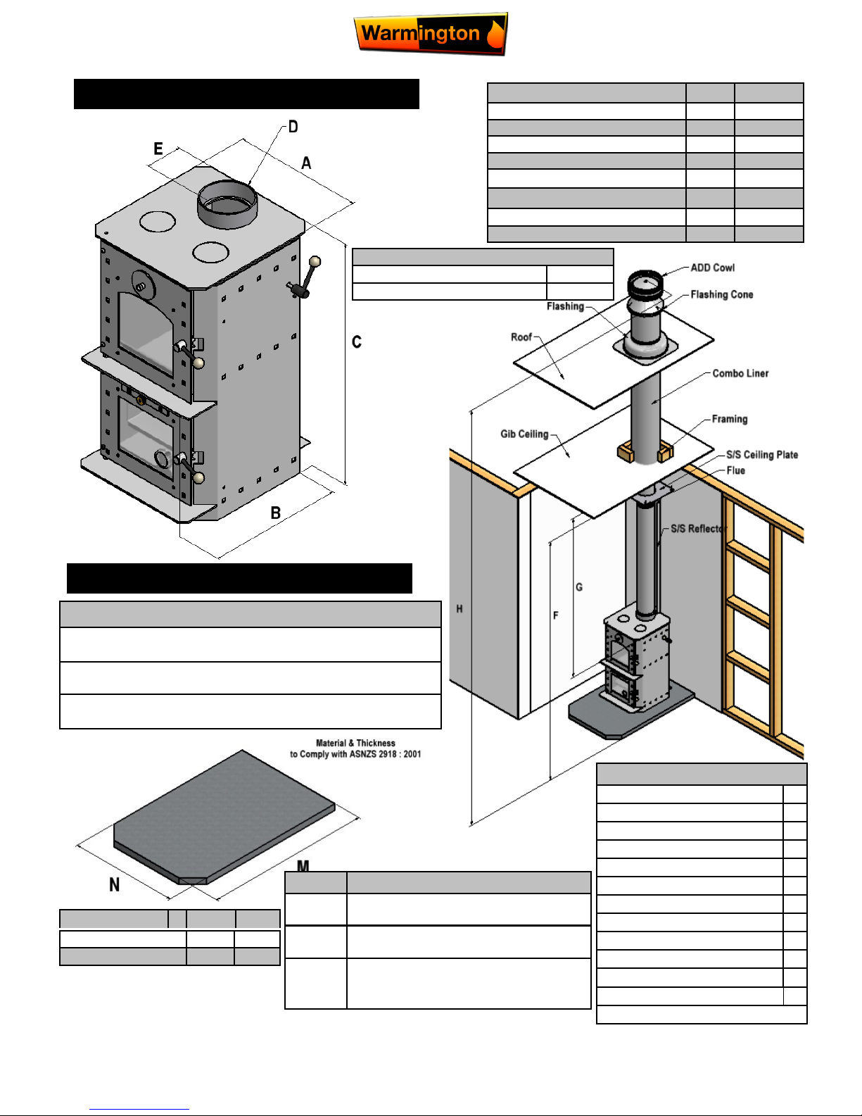
Cabinet Width A 436
Cabinet Depth B 509
Cabinet Height C 820
Flue Diameter D 150
To Flue Centre E 123
Ceiling Height F 2400
Minimum from fire to Ceiling G 1500
Height from Floor Protector H 4600
Check List
Fit Baffle (If Required)
Fit Bricks (If Required)
Fit Bottom Ash Pan
Fit Top Plate Inspection Discs
Fit Oven Trays
Fit Thermometer
Holding Down Brackets
Check Door Seals
Check Door Dampers
Check Flue Damper & Handle
Serial Number Check
Loading Badge
Packed By :
Minimum Flue Height
Flue Height 3600
Measured From Top of Cabinet C + 3600
FIREBOX DETAILS
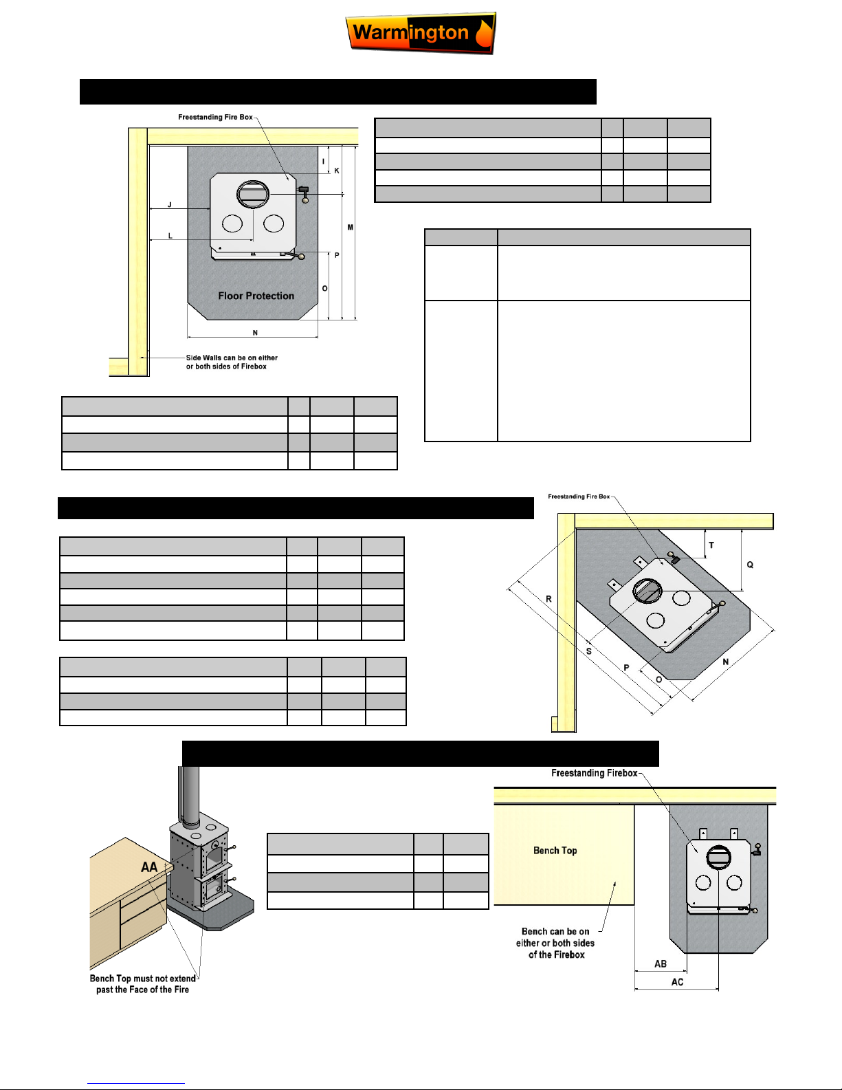
FLOOR PROTECTOR
Hearth Depth M 1128 903
Hearth Width N 660 660
Description 1. 2.
Note: Floor Protection
Floor Protectors are normally designed to suit each individual
“setting”.
The Studio Oven requires an “Insulating” Floor Protector of
75mm Thickness or more .
The Insulating Floor Protector is to Comply with
ASNZS 2918 : 2001
Situation
1. Combustible Surface without Flue
Shield.
2. Combustible Surface with stainless steel
reflective Flue Shield*
* Construction of Flue Shield must be in
accordance with ASNZS 2918 (minimum
Flue Shield height is 1200mm)
21 February 2017
All Dimension are in mm………….Copyright ©
4
Due to continued product improvement, Warmington Ind LTD reserves the right to change product specifications without prior no tification.
Description 1. 2.
To Wall Behind I 175 100
To Wall Side J 305 100
To Flue Centre (Back) K 298 223
To Flue Centre (Side) L 523 300
*Measurement taken from front ash lip
PLAN VIEW OF CLEARANCES TO COMBUSTIBLE S—STRAIGHT WALL INSTALL
Description 1. 2.
Hearth Projection O 300* 300*
Hearth Projection from Centre of Flue P 614 614
To Flue Centre – Corner Q 366 303
To Flue Centre – Corner R 518 429
To Wall Side – Corner T 150 100
Description
2. 3.
Hearth Depth M 903 837
Hearth Width N 660 660
Hearth Projection from Centre of Flue P 614 614
PLAN VIEW OF CLEARANCES TO COMBUSTIBLES—CORNER INSTALL
Description 1. 2.
Hearth Depth S 1123 1043
Hearth Width N 660 660
Hearth Projection from Centre of Flue P 614 614
CLEARANCES TO BENCH TOP FOR STUDIO OVEN
Description
mm
Bench Top Clearance AA 50
To Bench Top Side AB 352
To Flue Centre (Side) AC 570
Situation
1.
Combustible Surface with stainless steel reflective Flue Shield. Construction of Flue Shield
must be in accordance with ASNZS 2918
(minimum Flue Shield height is 1200mm)
2.
Non Combustible Surface and including walls
without Flue Shield , eg Concrete/Block/Brick/
ACC Block.
Re Clearance to a Non Combustible materials, walls or surfaces Ref to
ASNZS:2918:2001 3.2.1.
The clearance to a Non Combustible surface
and including wall can be less that 100mm if
a wet back is not fitted and no requirement
for maintenance.
21 February 2017
All Dimension are in mm………….Copyright ©
5
Due to continued product improvement, Warmington Ind LTD reserves the right to change product specifications without prior no tification.
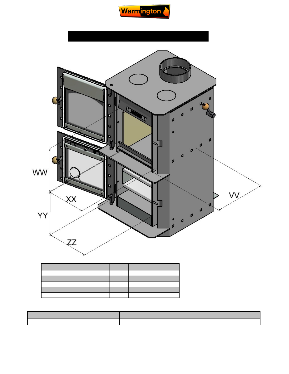
STUDIO OVEN INTERNAL MEASUREMENTS
Description
STUDIO OVEN
Internal Depth VV 295
Firebox Internal Height WW 205
Firebox Internal Width XX 241
Cooker Internal Height YY 281
Cooker Internal Width ZZ 260
Tested Fuel Load (Softwood)
Kg Fire Box Litres : Approx.
STUDIO OVEN up to 2.9 kg 29 Liters
21 February 2017
All Dimension are in mm………….Copyright ©
6
Due to continued product improvement, Warmington Ind LTD reserves the right to change product specifications without prior no tification.
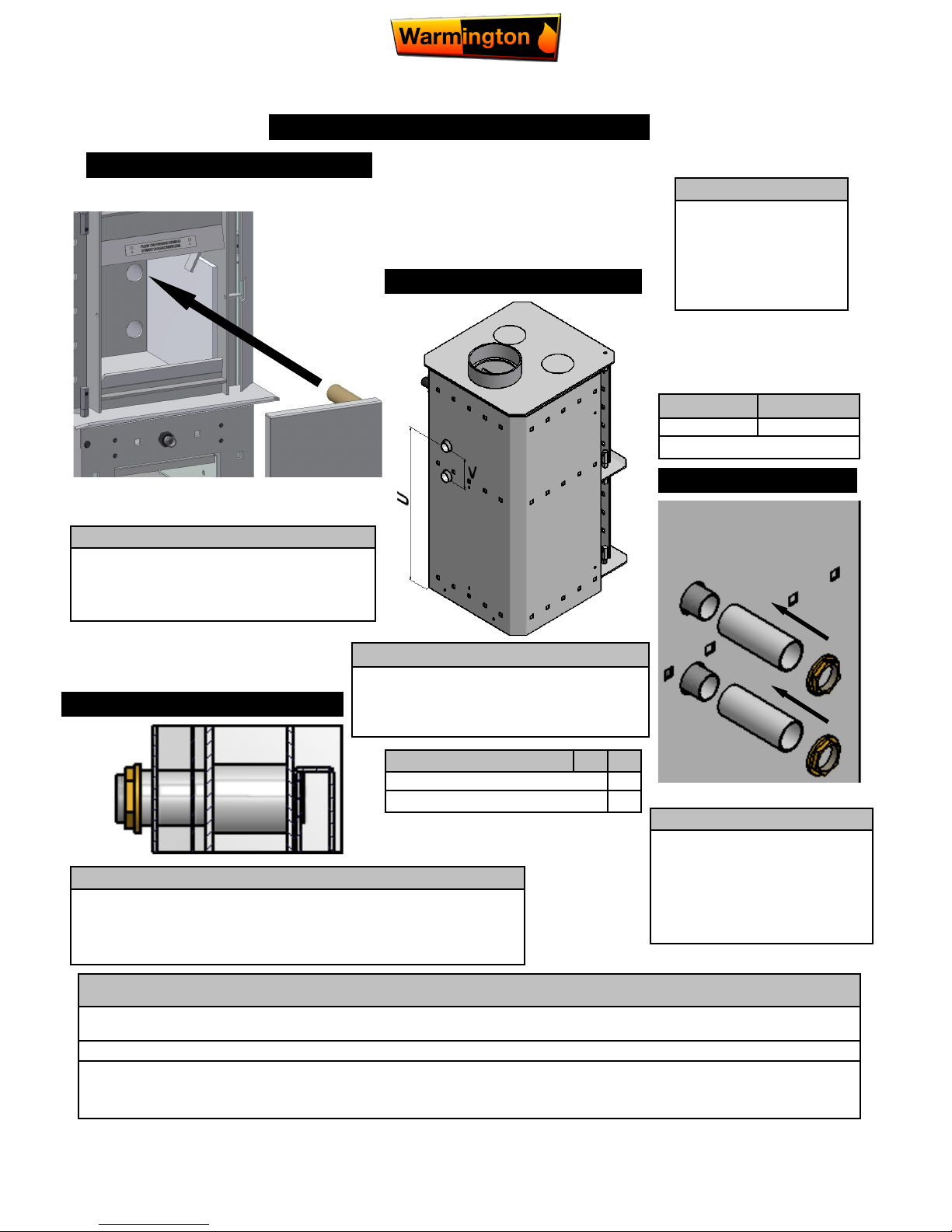
Note:
Cut Excess BSP pipe
off wet back to
length…..By Plumber.
Description
Height from Bottom of Unit U 560
Distance Between Outlets V 110
Power Out KW*
Wetback 2 Kw
*Value is approx.
WETBACK POSITION
STEP 1
STEP 2
Step1 :
Remove 2X Wetback Plugs & Fit Wetback
(as per Diagram above) into 2X Holes inside
Firebox .
Step 2 :
Once Wetback is in Place , the 2 BSP
Pipes should extrude out the back & past
the Fires Main Outer Wrap .
STEP 3
Step 3 :
With the 2X 100mm Galv Spacer Pipes supplied Slide over
BSP Pipe off the Wetback &
then secure with 2X Brass BSP
Nuts supplied .
STEP 4
BSP Brass Nut
100mmGalv
Spacer
Step 4 :
Once the Wetback is secured in place , ensure that
Water is in the Wetback before Operating the Fire .
Damage will result if the Wetback is dry .
Note:
Consult your plumber for wet back system configurations and operation.
Wet back is to be fitted to an internal heat-sync (e.g. Hot water cylinder / Radiator / Under floor heating etc…
Ensure that Water is in the Wetback before Operating the Fire . Damage will result if the
Wetback is dry .
 Loading...