

Warmington Studio Stove, Studio OH-AH 14 Installation Instructions Manual
17 October 2014
All Dimension are in mm………….Copyright ©
1
Due to continued product improvement, Warmington Ind LTD reserves the right to change product specifications without prior no tification.
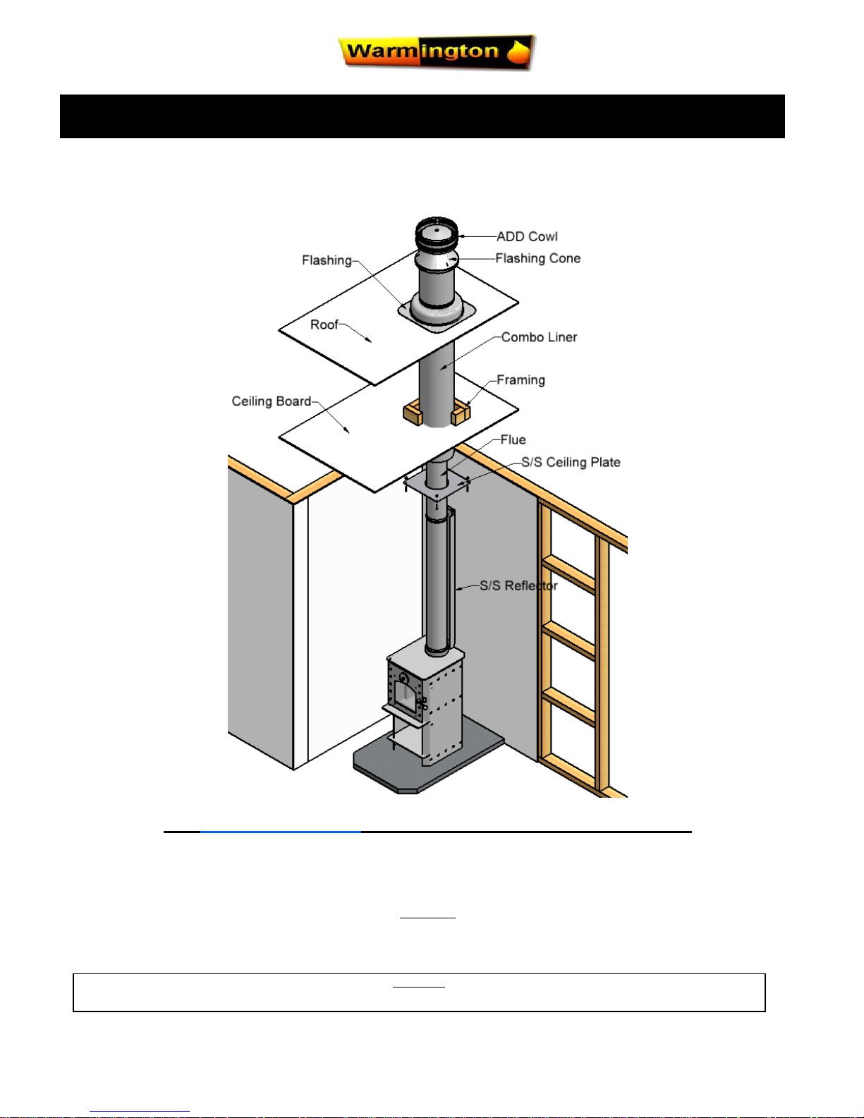
Studio Stove
Visit www.warmington.co.nz for Spec’s, DWG’s and PDF uploads of Fires
Fire, Flue System and instructions to comply with ASNZS 2918:2001
Keep these Instructions for future reference……Ensure that you have the correct and current Installation details for the Warmington Fire
Installation
The Warmington unit is to be Installed by a Certified Warmington Installer or an Approved NZHHA Installation Technician .
See www.homeheat.co.nz/members for a Certified NZHHA SFAIT Installer in your area .
CLEARANCES TO COMBUSTIBLE SURFACES UNLESS STATED
IMPORTANT
Read all the Instructions carefully before commencing the Installation. Failure to follow these Instructions may result in a Fire Hazard and void the warranty
Studio Stove—Clean Air Approved Wood Burner
Installation Instructions
17 October 2014
All Dimension are in mm………….Copyright ©
2
Due to continued product improvement, Warmington Ind LTD reserves the right to change product specifications without prior no tification.
Manufactured by: Warmington Industries Ltd - PO Box 58652 Botany 2163, Auckland NZ
Model: ……Studio Stove
Serial No: S - ……………………
Emission Report No: 05/1196 Applied Research Services LTD
TESTED TO AS/NZS 4013.
BURN ONLY UNTREATED WOOD WITH A MOISTURE CONTENT LESS THAN 25% (DRY BASIS)
AVERAGE PARTICULATE EMMISSION FACTOR BURNING SOFTWOOD – 0.95g/kg
MAXIUM AVERAGE HEAT OUTPUT BURNING SOFTWOOD – 8.9KW
OVERALL AVERAGE EFFICIENCY BURNING SOFTWOOD - 69.9%
When Tested in Accordance with AS/NZS 4012
Council Authorization No: Expiry date:
ECan 071226 01 Jan 9999
NCC 071226 N/A
Performance may vary from tested values depending on actual operating conditions.
Date of installation: _____/_____/20_____
Free down load of operating instructions from the website .
www.warmington.co.nz
17 October 2014
All Dimension are in mm………….Copyright ©
3
Due to continued product improvement, Warmington Ind LTD reserves the right to change product specifications without prior no tification.
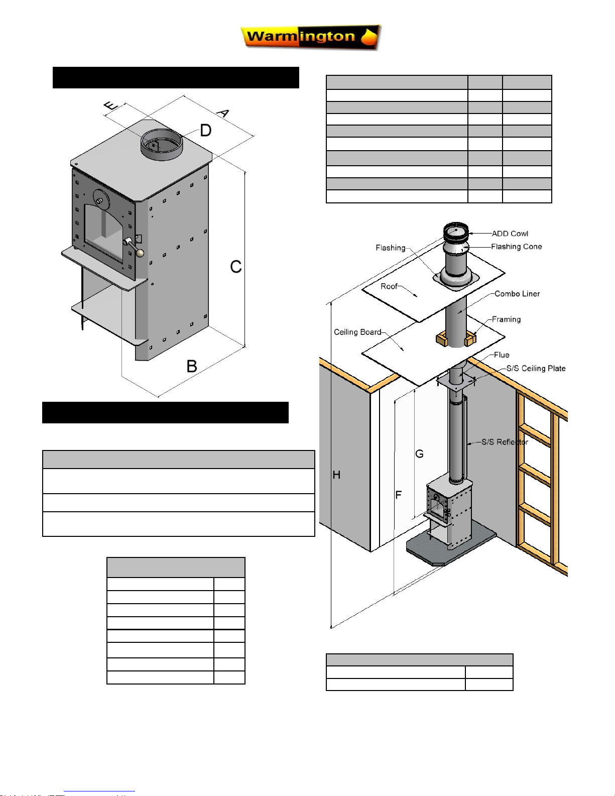
Description
Cabinet Width A 400
Cabinet Depth B 520
Cabinet Height C 820
Flue Diameter D 150
To Flue Centre E 123
Minimum Ceiling Height F 2400
Minimum from fire to Ceiling G 1500
Height from Floor Protector H 4600
Emissions levels (g/kg) 0.95g/kg
Check List
Baffle
Holding Down Brackets
Check Door Seal
Check Damper
Bricks (If Required)
Serial Number Check
Loading Badge
Packed By
Minimum Flue Height
Flue Height 3600
Measured From Top of Cabinet C + 3600
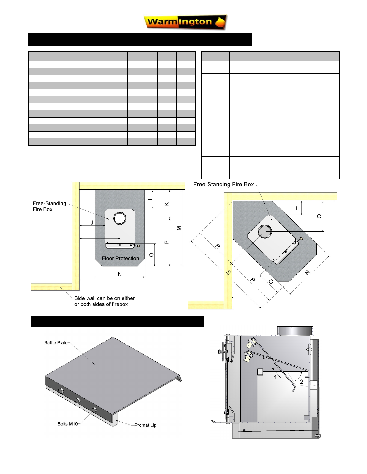
FIREBOX DETAILS
FLOOR PROTECTOR
Note: Floor Protection
Floor Protectors are normally designed to suit each individual
“setting”.
The Studio Stove requires a “Ash Hearth” Floor Protector
The Floor Protector is to Comply with
ASNZS 2918 : 2001
17 October 2014
All Dimension are in mm………….Copyright ©
4
Due to continued product improvement, Warmington Ind LTD reserves the right to change product specifications without prior no tification.
Description
1. 2. 3.
To Wall Behind I 325 250 100
To Wall Side J 325 325 100
To Flue Centre (Back) K 448 373 223
To Flue Centre (Side) L 525 525 300
Hearth Depth M 1062 987 837
Hearth Width N 660 660 600
Hearth Projection O 300* 300* 300*
Hearth Projection from Centre of Flue P 614 614 614
To Flue Centre -Corner Q 453 378 303
To Flue Centre -Corner R 641 535 429
Hearth depth -Corner S 1255 1149 1039
To Wall Side - Corner T 250 175 100
*Measurement taken from front ash lip
Situation
1. Combustible Surface without Flue Shield.
2. Combustible Surface with stainless steel
reflective Flue Shield*
3. Non Combustible Surface and including
walls without Flue Shield , eg Concrete/
Block/Brick/ACC Block.
Re Clearance to a Non Combustible
materials, walls or surfaces Ref to
ASNZS:2918:2001 3.2.1.
The clearance to a Non Combustible
surface and including wall can be less
that 100mm if a wet back is not fitted
and no requirement for maintenance.
* Construction of Flue Shield must be in
accordance with ASNZS 2918 (minimum
Flue Shield height is 1200mm)
PLAN VIEW OF CLEARANCES TO COMBUSTIBLES - STRAIGHT & CORNER
BAFFLE POSITION
17 October 2014
All Dimension are in mm………….Copyright ©
5
Due to continued product improvement, Warmington Ind LTD reserves the right to change product specifications without prior no tification.
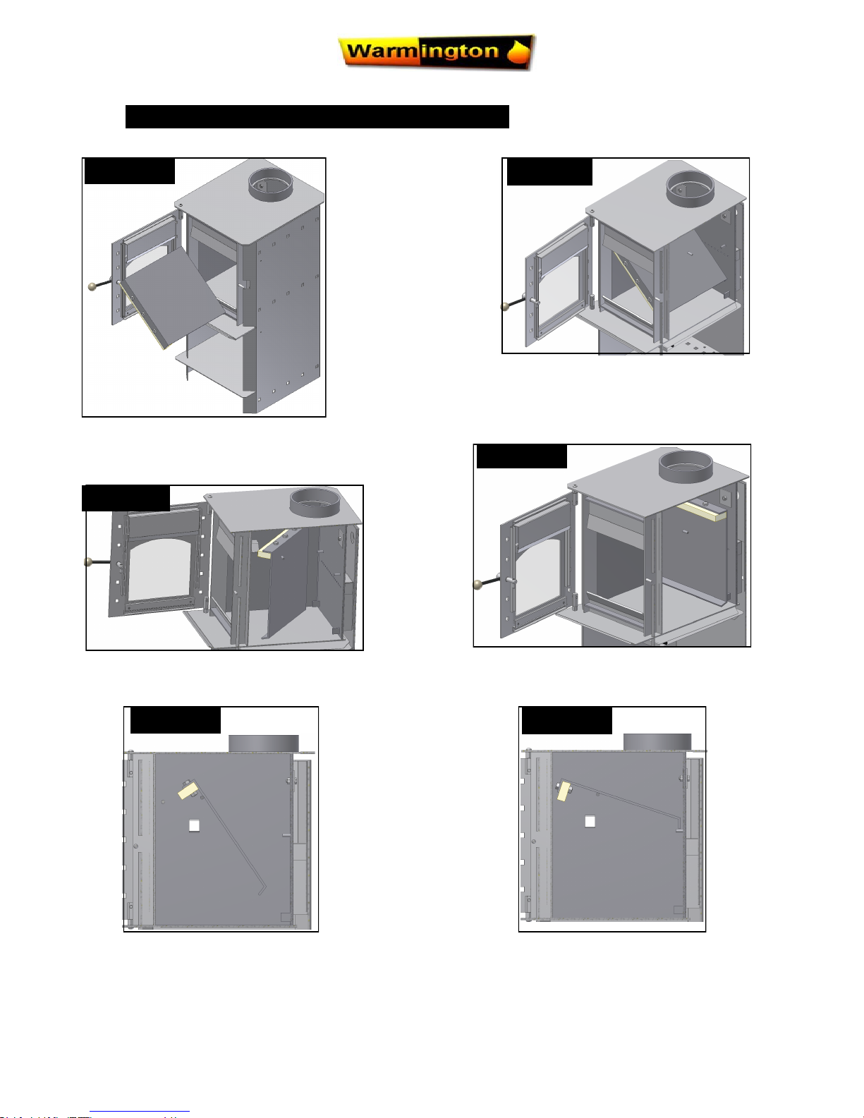
STEP : 1
FITMENT & REMOVAL OF BAFFLE
STEP : 2
STEP : 3
STEP : 4
STEP : 5
STEP : 6
Remove Ash & Studio Bricks
Push Baffle right to the Back of Firebox
Tilt Studio Baffle on an Angle & Slide in
through Door Frame
Move Baffle forward to sit on Pins
Move the Back of the Baffle up to sit
on the Pins at the Back of the Firebox
Rotate Baffle 90 degrees
 Loading...