

Warmington SG SN 1500, EG SN 1500, EG SN 1250, SG SN 1250, SG-EG 600 Twin Installation Manual
...
14 June 2016
Due to continued product improvement, Warmington Ind LTD reserves the right to change product specifications without prior no tification.
All Dimension are in mm
1
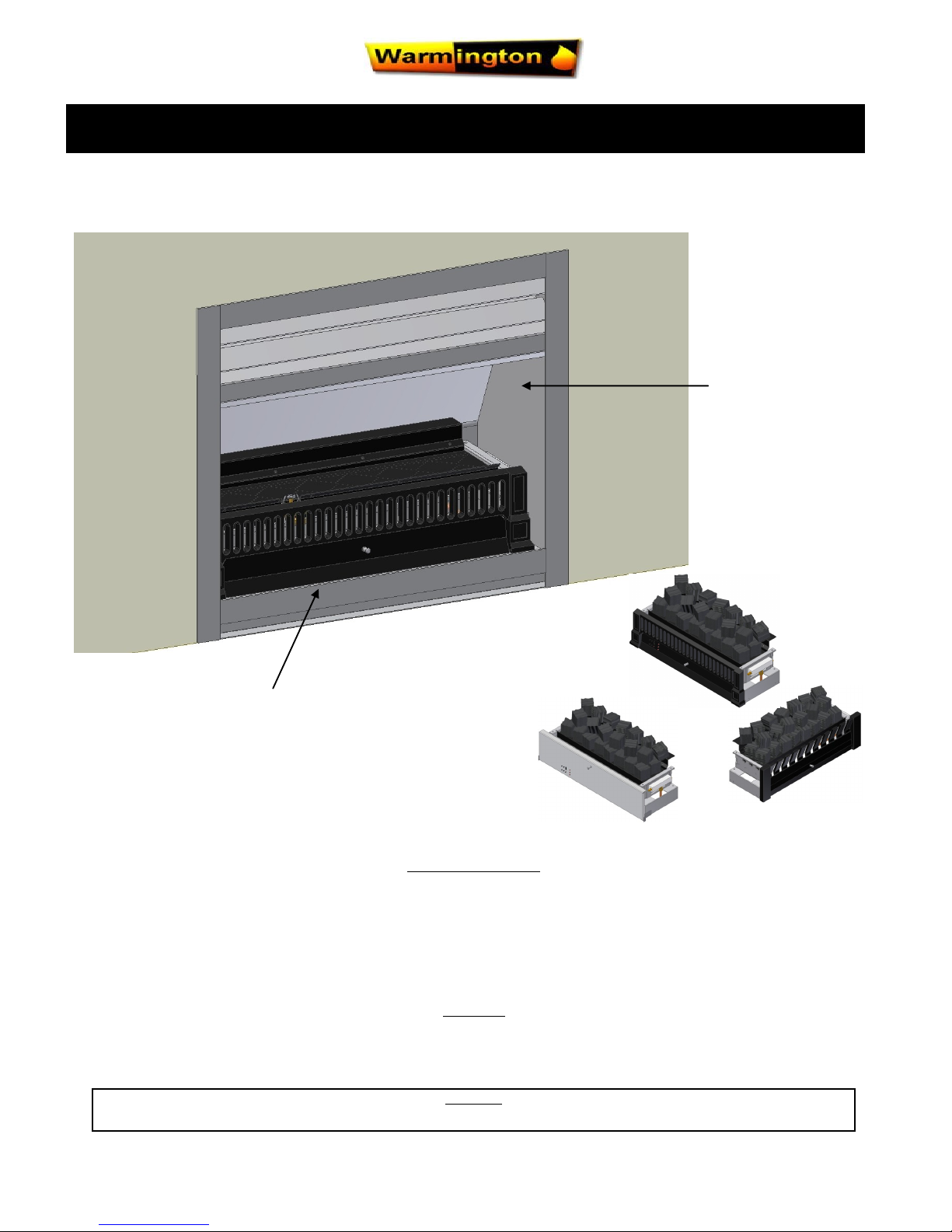
SG Gas Burner into a Warmington SI Wood Open Fire
Installation Guide Only
SG 700-780-900-1100 Burner Only
Traditional Grate
& Burner
Pure Grate
& Burner
Classic
Grate
Warmington SG
Gas Burner.
Warmington
SI Open
Wood Firebox.
The fireplace is constructed and tested to comply with NZS 4558(int):2013 “Decorative gas log and other fuel effect appliances”.
Keep these instructions for further reference. Ensure that you have the correct and current installation details for the Warmington fireplace.
Installation
The Warmington unit is to be installed by a certified Warmington installer or an approved NZHHA installation technician.
See www.homeheat.co.nz/members for a certified NZHHA SFAIT Installer in your area.
A licenced certified gas fitter and licenced electrician are required to run power and gas supplies as required to the unit and any commissioning as part of the
installation process.The heater must be installed according to these instructions and in compliance with all relevant building, gas fitting, electrical and other
statutory regulations.
IMPORTANT
Read all the instructions carefully before commencing the Installation. Failure to follow these instructions may result in a fire hazard and void the warranty
Related documents
Fire and flue system installation, and instructions to comply with NZS 5601.1:2013,
3645.1(Int):2010, 3645.2(Int):2010, 5266:2014, 2918:2001.

14 June 2016
Due to continued product improvement, Warmington Ind LTD reserves the right to change product specifications without prior no tification.
All Dimension are in mm
2
POINTS TO CONSIDER PRIOR TO INSTALLATION
INSTALLATION ORDER OF OPERATIONS
Location of the Fire. Open Fires are better located at one end of a room or area, as they project the heat away from their opening .
Venting to the Cavity.
This air is to allow the Cavity to Vent the Warm Air. This Warm Air helps keep the Fire and Flue System form getting to Cold . If the Flue and Fire get to Cold the System may soot often and require
cleaning. Each Fire has different ways of venting the cavity .
The Topography of the Land .
The slope and position of the Land in relation to the Home has a bearing on how the wind will interact with the Fire and Flue System. Care needs to be taken to ensure that the Flue Termination is in the
correct position to maximise performance .
The Prevailing Wind.
Care needs to be taken to ensure that the Flue Termination is in the correct position as wind and gusts that hits the Flue and Cowl System may overcome the Cowl and draft back down the Flue into the
Home. This can be a combination of down draft and high pressure.
Hearth and Plinth:
The height of the Hearth off the Floor. The Finishing that is to be used on the hearth is to be allowed for at the de sign stage.
Positioning of the Flue System:
There is a maximum distance that an Offset Flue can be Installed. Reference to relevant standards.
Flue and Fire Clearance:
To be maintained to the Manufactures Instructions.
Pressure Differential, Venting & External Air into the Building :
All fires need air to burn and draw correctly, Kitchen Fans, Air Conditioning units, High Wind Zones, Naturally formi ng Draft spaces, can all have an effect on the pressure difference from inside the
building to the outside. A lower pressure in the building may induce a draft down the flue system and back into the building causing the fire to smoke or spill into the building. Care needs to be taken at
the design and installation stage to adequately vent the building, or some mechanical system to ensure that there is always a neutral or positive pressure at the fireplace and a negative
pressure at the flue outlet. This will ensure that the draft in the flue system is always to the outside.
“CAITEC AIR” the limits and requirements. See details in these Specs, on www.warmington.co.nz or contact your local Agent.
Wind Noise:
You may encounter wind noise in some installations. It is recommended to use an enclosed chase with a chimney pot to help reduce noise. There will always be some noise from the flue systems of all
fireplaces.
Prior to Construction and Installation Important Notes:
1. Consult a licenced certified gas fitter for correct gas installation.
2. Install to current standards.
3. Install to manufacture’s specifications.
4. All new Installations require a Local Council Consent No/Permit Application to be done .
5. Allow for Gas & Power supply to Cavity.
6. For special requirements concerning Materials (Timber Mantle and Surrounds) within close proximity of Warmington products, please contact your
local Warmington Technical Consultant.
Install Procedure by Certified Gasfitter or approved “Warmington Installer”, see “www.homeheat.co.nz” go to Members & follow
steps to get a Certified NZHHA SFAIT Fire Installer in you Region. Installation to comply with current standards.
Ensure that the gas appliance is fitted and installed to the appropriate gas code
and standard, and that all checks and test have been correctly carried out.
Maintenance:
Visually Inspect Fireplace and Flue System. Ensure that the Firebox is operating according to Manufacture’s Instructions, Fire & Burner may
Require to be serviced by Certified Gasfitter annually.
14 June 2016
Due to continued product improvement, Warmington Ind LTD reserves the right to change product specifications without prior no tification.
All Dimension are in mm
3
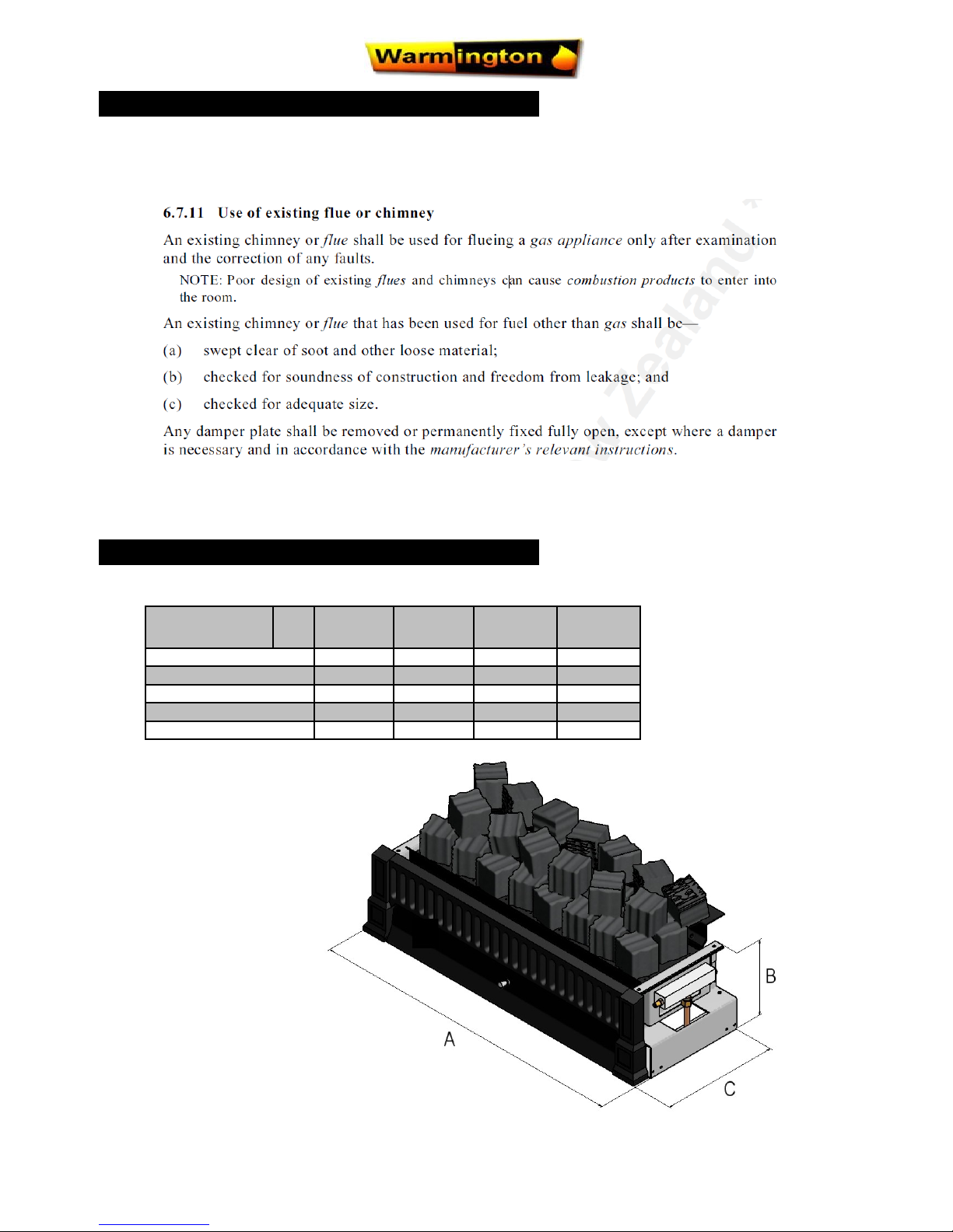
Burner SG
700
SG
780
SG
900
SG
1100
Burner Width A 674 754 874 1074
Burner Height B 205 205 205 205
Burner Depth C 272 272 272 272
Flue Diameter Min J 200 200 250 250
Flue CSA mm K 31 416 31 416 49 087 49 087
WARMINGTON BURNERS
NOTE: IMPORTANT INFORMATION FROM THE STANDARD
Installation to comply with current standards. When installing a fitted open gas fire with an existing chimney section 6.7.11 in
NZS 5601 is particularly relevant, see quote below:
14 June 2016
Due to continued product improvement, Warmington Ind LTD reserves the right to change product specifications without prior no tification.
All Dimension are in mm
4
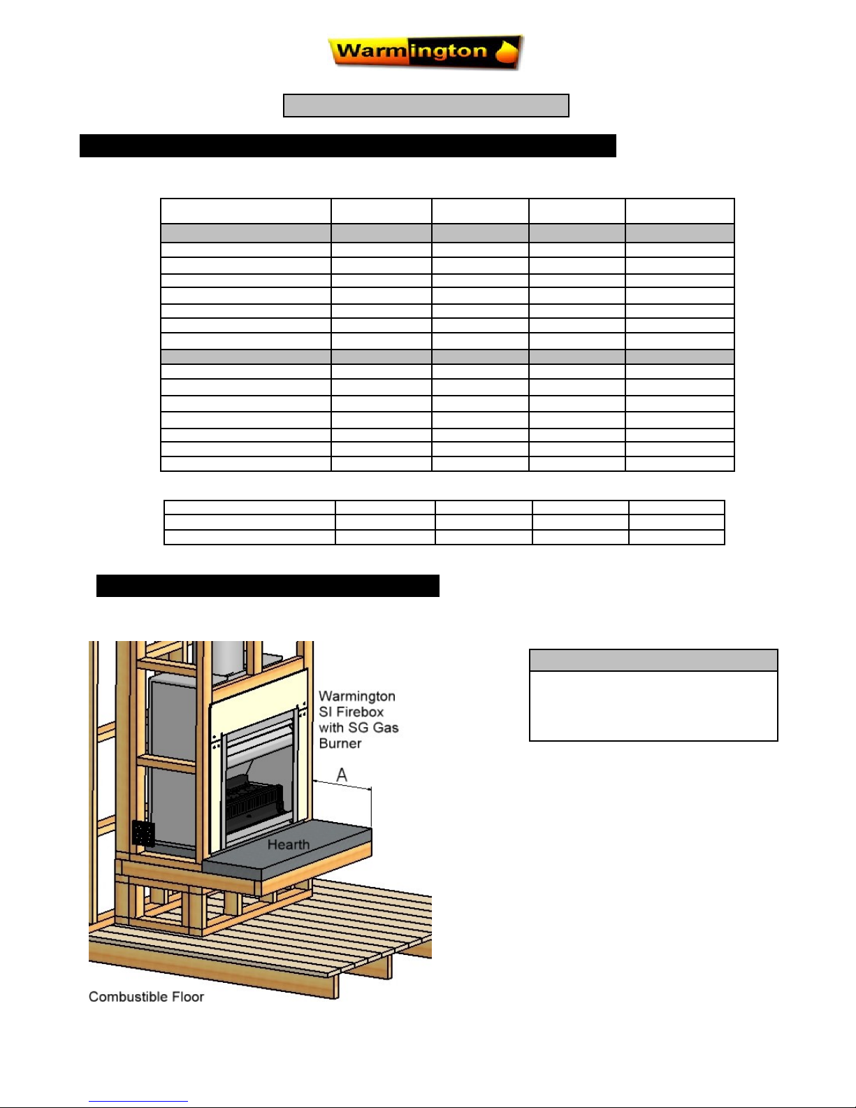
HEARTH CLEARANCES
Note: For Combustible Floors
Minimum Hearth of 300mm (A) must be
maintained at any given height.
* Inlet Pressure not to exceed 4.0KPa
GAS SPECIFICATIONS Tested to current gas standards
NOTE : All Test Pressures are tested by a Independent Test Lab
MODLE SG 700 SG 780 SG 900 SG 1100
LPG
Nominal Pressure kPa
2.75 kPa 2.75 kPa 2.75 kPa 2.75 kPa
Nominal Injector Size mm
2 X 1.1mm 2 X 1.2mm 2 X 1.3mm 2 X 1.4mm
Burner Pressure High kPa
2.5 2.5 2.5 2.5
Burner Pressure Low kPa
0.75 0.75 0.75 0.75
MJ/h
29 38 42 50
Flame Effect Output Only
Effect Effect Effect Effect
Supply Pipe Size dia—min
3/8” 3/8” 1/2” 1/2”
Natural Gas
Nominal Pressure kPa
1.5 kPa 1.5 kPa 1.5 kPa 1.5 kPa
Nominal Injector Size mm
2 X 1.8mm 2 X 2mm 2 X 2.2mm 2 X 2.4mm
Burner Pressure High kPa
1.0 1.0 1.0 1.0
Burner Pressure Low kPa
0.3 0.3 0.3 0.3
MJ/h
35 41 48 60
Flame Effect Output Only
Effect Effect Effect Effect
Supply Pipe Size dia—min
3/8” 1/2” 1/2” 1/2”
IMPORTANT NOTES :
Lab. Test No
GL 923 GL 900 GL 834 GL 876
Lab. Test Dates
20/04/2010 26/02/10 26/06/09 24/12/09
ESS Declaration No: 1149420106 1149520106 1149720106 1149820106
 Loading...